1200 - Sewing machine HUSQVARNA - Free user manual and instructions
Find the device manual for free 1200 HUSQVARNA in PDF.
User questions about 1200 HUSQVARNA
0 question about this device. Answer the ones you know or ask your own.
Ask a new question about this device
Download the instructions for your Sewing machine in PDF format for free! Find your manual 1200 - HUSQVARNA and take your electronic device back in hand. On this page are published all the documents necessary for the use of your device. 1200 by HUSQVARNA.
USER MANUAL 1200 HUSQVARNA
Gauges and service 6-7
Visual control of details 8-12
13-22
8
Presser foot 8
Feed dog 8
Bobbin case 9
Hook cover 9
Hook 10
Driver 10
Main switch and feed dip button 10
Foot control 11
Cog belt, short 12
Cog belt, long 12
Wiring diagram 13
Service casette 14-17
Switch for presser foot lift 18
Buttonhole meter 18
Lower thread indicator 19
Stepmotors: Thread tension, sewing head, guide, side motion 20
Transformer 1050/1070/1090 21
Transformer 1100/1200 22
Electronic board 1050/1070/1090 21
Electronic board 1100/1200 22
Setting instructions
1 The hook gear 23
2 The gap between the hook cover and the driver 24
3 Presser foot, parallelism to the stitch plate 25
4 Setting the presser foot at right angles to the feeding direction 25
5 Setting of the step motor of the sewing head 26
6 Setting of the needle in relation to the presser foot 27
7 The gap between the hook and the needle 28
8 Setting the stitch plate in relation to the needle 29
9 Timing of the hook in relation to the needle 30
10 Needle height 31
11 Thread tension of the bobbin case 32
12 Upper thread tension 32
13 Setting the thread tension of the step motor 33
14 The setting of the thread take-up spring 33
15 Parallelism of the feed dog 34
16 The sideways setting of the feed dog 34
17 The feed dog height 34
18 The lengthwise movement of the feed dog 35
19 The bobbin-winding device 35
20 The balance of the stitch length 36-40
21 Pre-setting of the step motor of the guide 41
22 Pre-setting of the step motor of the side motion 42
23 The sideways setting of the feeding mechanism 43
Dismounting- and mounting instructions
Rear cover, lower cover 44
Front cover 44
Parts of the front cover 44
Parts of the front cover 1100/1200 program memory 45
Parts of the front cover 1100/1200 foil keyboard 46
Transformer 47
Main motor 48
Bobbin-stop 48
Circuit board 48
Foot control 49
Feeding guide compl 50
Connecting rod 51
Feeding mechanism unit with stitch regulator fork 51
Thread tension device compl 52
Driver 52
Lower shaft 53
Sewing head 54
Arm shaft 55
Side motion mechanism cpl 56
57
SETTINGS
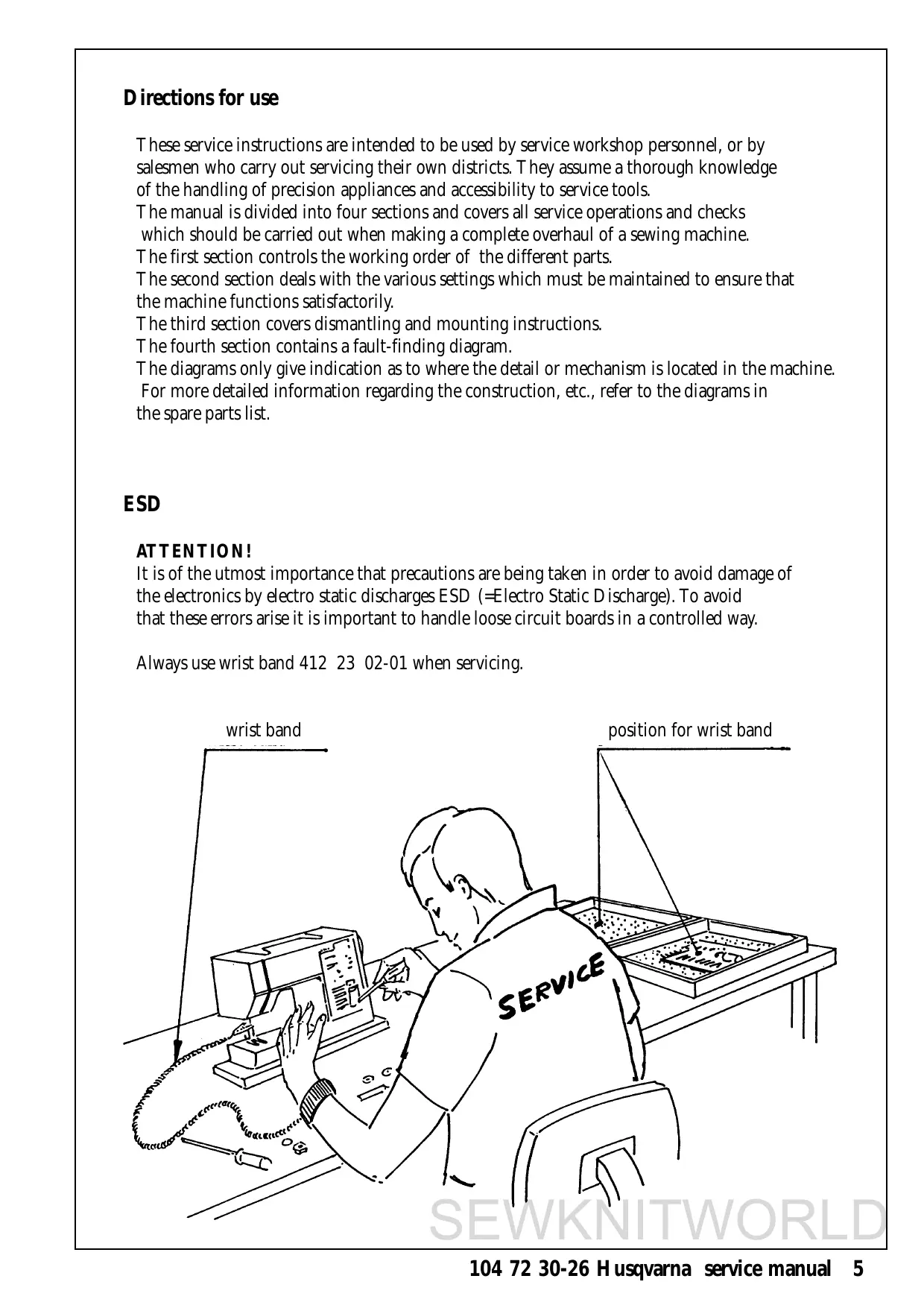
Directions for use
These service instructions are intended to be used by service workshop personnel, or by salesmen who carry out servicing their own districts. They assume a thorough knowledge of the handling of precision appliances and accessibility to service tools.
The manual is divided into four sections and covers all service operations and checks which should be carried out when making a complete overhaul of a sewing machine.
The first section controls the working order of the different parts.
The second section deals with the various settings which must be maintained to ensure that the machine functions satisfactorily.
The third section covers dismantling and mounting instructions.
The fourth section contains a fault-finding diagram.
The diagrams only give indication as to where the detail or mechanism is located in the machine.
For more detailed information regarding the construction, etc., refer to the diagrams in the spare parts list.
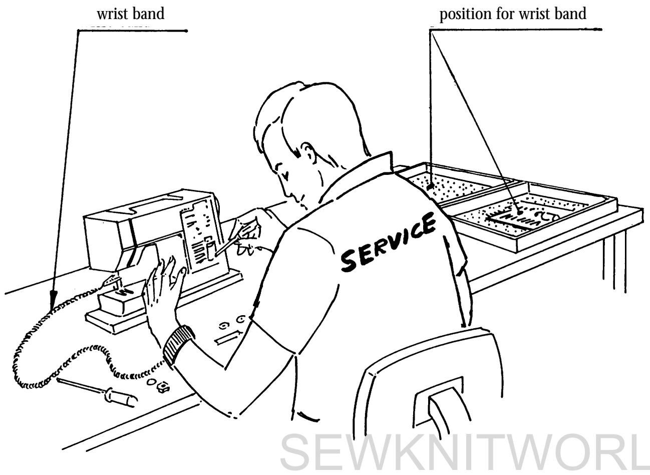
ESD
ATTENTION!
It is of the utmost importance that precautions are being taken in order to avoid damage of the electronics by electro static discharges ESD (=Electro Static Discharge). To avoid that these errors arise it is important to handle loose circuit boards in a controlled way.
Always use wrist band 412 23 02-01 when servicing.
Setting gauges
A reasonable requirement in a domestic sewing machine is that it should able to sew all types of fabrics used in the home. The settings made when assembling and sewing-in the machines are those most suited to give the best results in the majority of fabrics and fabric combinations. In doing so, consideration has been given to the requirements of different markets. This does, however, mean that when sewing extreme fabrics, better results may be obtained in certain cases by altering the settings. It must be pointed out that these altered settings can cause poorer results on more normal fabrics. How the different standard ratings are set can be seen from the description under each setting instruction. The following list of setting gauges and service tools is chiefly intended as an indication as to how service men or service workshops should be equipped.
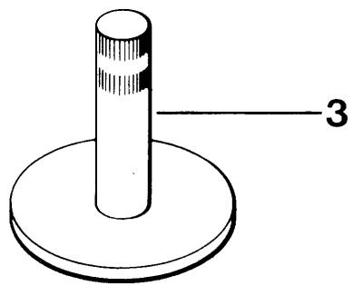
The needle is often used as a setting gauge. The setting ratings are adapted to needle size 90 and when setting in the feed direction, the needle should be set in the middle of the needle hole. (Page.29). Be sure to use an undamaged needle.
- Gauge for setting the timing of the hook in relation to the needle (P.30). Ref. No 411 17 52-01.
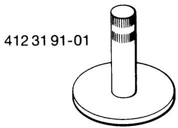
- Gauge for the gap between the hook cover and driver. (P.24). Ref. No 412 31 91-01.
- Gauge for feed dog height (P.34). Ref. No 411 49 93-01.
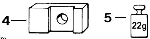
- Weight for setting the thread tension of the bobbin case (P.32). Ref. No 412 15 83-01 (=22 g.)
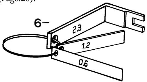
- I. Distance gauge (1,2mm) to set the step motor of the sewing head (P.26). II. Gauge for the centre position of the needle (P. III. Distance gauge (0,6mm) for the pre-setting of step motor of the guide older version (P.41). Ref. No compl. I-III. 412 27 60-01.
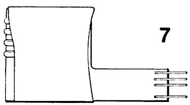
- Electronic unit for testing the function of the transformer and the stepmotors. See separate instructions enclosed. Ref. No 412 02 56-01.
- Service casette for 1100, 1200 (P.14-15). Ref. No 412 17 29-15.
8
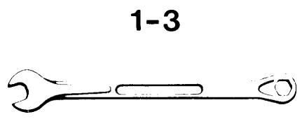
Service tools
- Fixed spanner 10mm to set the belt, long (P.12) and the gap between the hook and the needle (P.28). Ref. No 411 85 99-01
- Fixed spanner 5mm to set the stitch plate in relation to the needle (P.29). Ref. No 411 85 98-01
- Fixed spanner 5,5mm for the sideways setting of the feed dog (P.34). Ref. No 411 54 31-01.
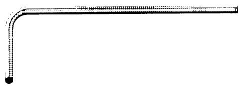
- Adam keys:
-0.9mm for the timing of the step motor of the thread tension (P.33).
Ref. No 412 27 71-01.
-1,5mm for needle clamp and step motors.
Ref. No 411 66 89-01.
-2,5mm for the timing of the hook in relation to the needle (P.30) and for the gap between the hook cover and the driver (P.24).
Ref. No 411 86 01-01. - Shortened adam key 2,5mm for the setting of the presser foot (P.25) and of the needle in relation to the presser foot (P.27). Ref. No 412 27 65-01.
- Key to set the stitch length balance (P.36-40). Ref. No 412 27 66-01.
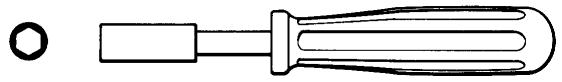
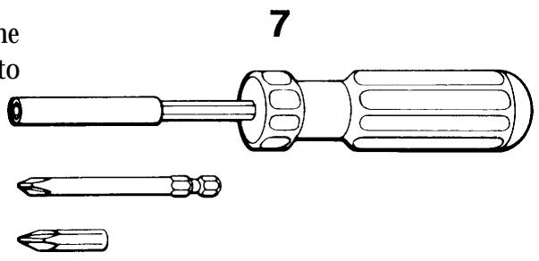
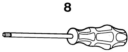
- Magnetic screwdriver with two separate heads. Ref. No 411 54 33-01.
- Screwdriver Torx 10
Ref. No 412 36 48-01.
Screwdriver Torx 20
Ref. No 412 36 49-01.
Screwdriver Torx 25
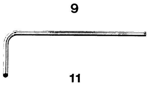
Ref. No 412 36 50-01. - Angle key for Torx 6 Ref. No 412 27 67-01.
10.Wristband for ESD Ref. No 412 23 02-01.
11.Extractor tool (p. 45). Ref. No 412 27 98-01.
4-5
6
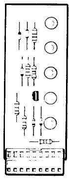
VISUAL CONTROL OF DETAILS
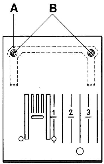
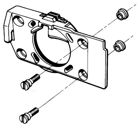
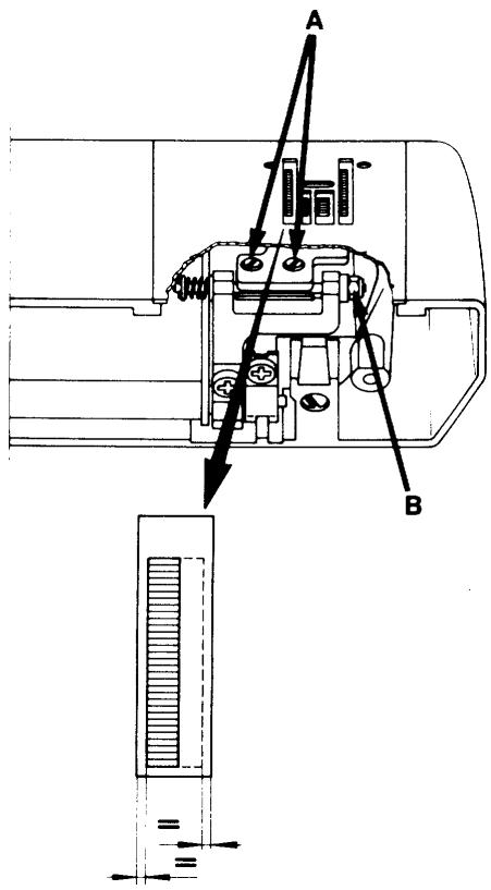
Stitch plate
Requirements
The stitch plate must not be damaged in any way.
Particular attention should be paid to possible damage or unevenness around the needle hole.
Action
Exchange the damaged stitch plate.
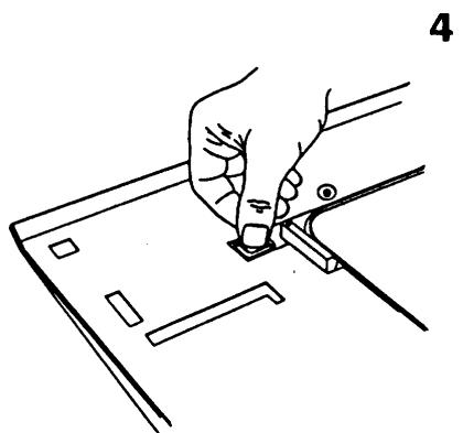
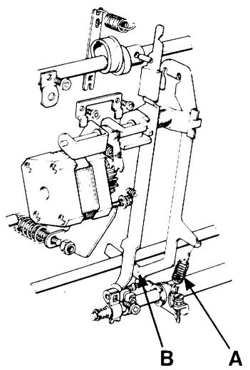
Mounting of a new stitch plate
In order to get the stitch plate into the correct position it should be first mounted with the spring (A) and screws (B) somewhat loose. Thereafter remove the stitch plate, fasten the screws an remount the stitch plate.
Setting to needle, (P.29).
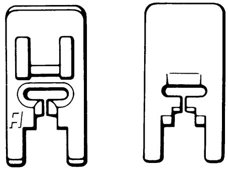
Presser foot
Requirements
There should be no scratches on the underneath of the presser foot.
Action
Exchange a damaged presser foot.
Comments
How the fabric is held between the presserfoot and the stitch plate plays an important role in the stitch formation. Refer to all presser feet.
See Operating Manual.
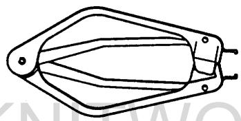
Feed dog
Requirements
The top side of the feed dog must not be damaged in any way, e.g. broken teeth etc.
It should be free from fluff and pieces of thread.
Compare with Operating Manual:
"Care of the machine".
Action
The faulty dog should be exchanged.
Remove the stitch plate.
Undo the screws and replace the feed dog.
As regards to the settings of the feed dog (P.34-35).
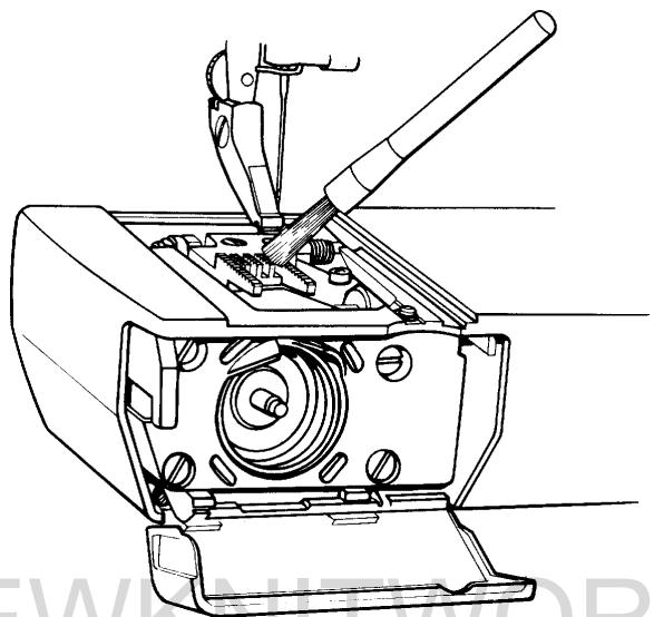
Bobbin case
Requirements
The thread tension spring, in its whole width, must be parallel to and press against the side of the bobbin case.
Action
Remove any fabric dressing which may have fastened under the thread tension spring.
Damaged thread tension spring is to be exchanged.
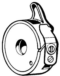
Comments
Deposits from fabric or thread can fasten on the spindle of the hook.
In that case the spindle should be carefully cleaned with the brush in the accessory box.
At the same time make sure that pieces which may have become wound around the spindle are removed.
Thread tension of the bobbin case, (P.32).
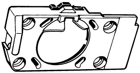
The hook cover
Requirements
The inside of the hook cover must not be damaged.
Action
Damaged hook cover must be exchanged.
Regarding the gap between the hook cover and the driver, (P.24).
Comments
The inside of the hook cover forms a support for the hook and the bridge above the finger of the bobbin case supports the thread, so that the thread loop is formed on the correct side of the needle.
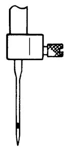
The hook
Requirements
The tip of the hook (A) and surface (B) must not be damaged.
Action
Exchange the damaged hook.
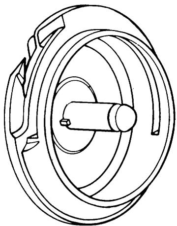
The driver
Requirements
The surface of the driver against the hook must not be damaged, worn or uneven in any way which might hinder the passage of the thread.
Action
Damaged hook is to be exchanged (P.52).
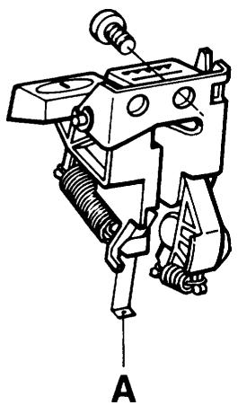
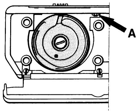
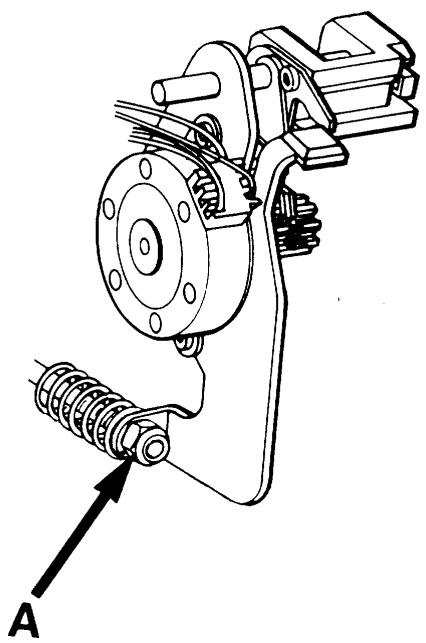
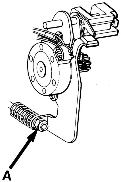
The main switch and feed dip button
If the main switch or the feed dip button doesn't work satisfactorily, remove the rear cover and front panel, (P.44). Exchange the complete unit or spring (A).
The foot control
Requirements 1
The speed should be continuously controllable from the lowest r / min to full speed.
Action
Test the foot control on a machine that is known to operate properly. If it does not work, exchange the whole control, alternatively the cord device or the potentiometer.
Requirement 2
The cable should be easily extractable from the cord device of the foot control and after pulling the cable slightly it should be rewound on the cord device.
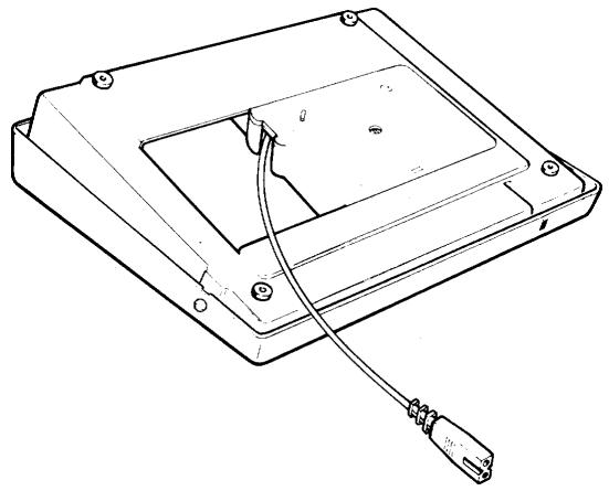
Action
The foot control or the cord device are to be exchanged. Dismantling (P.49).
The foot control
Requirements
The speed should be continuously controllable from the lowest r / min to full speed.
Action
Test the foot control on a machine that is known to operate properly. If it does not work, exchange the whole control, alternatively the potentiometer. Dismounting (page 49).
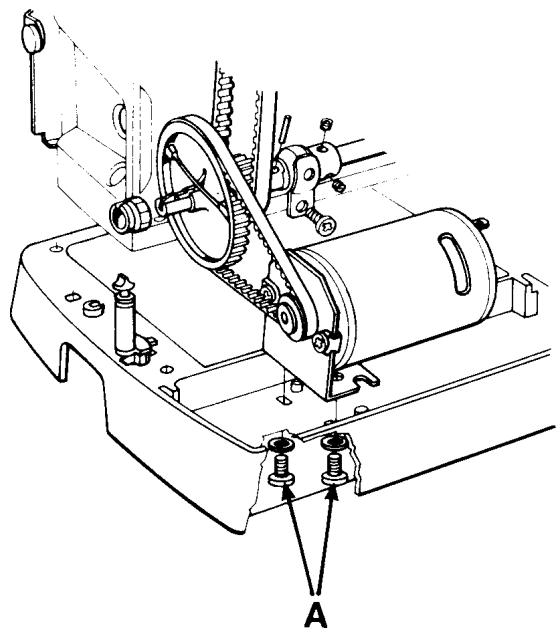
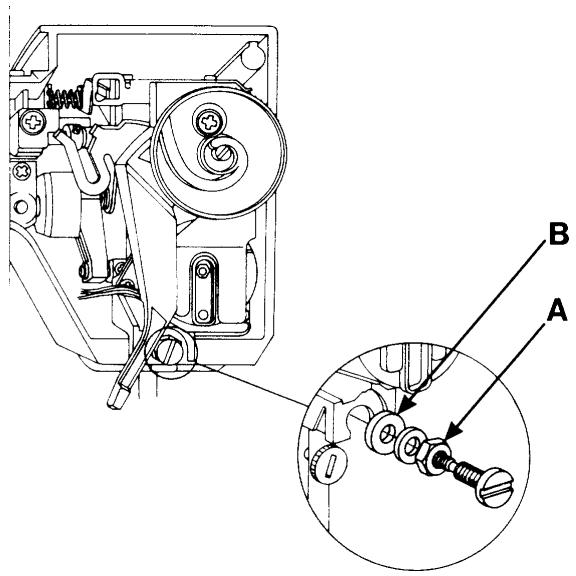
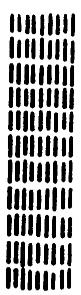
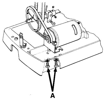
The cog belt, short
Requirements
The belt tension should not be so loose that it permits slipping when the machine is locked and the foot control is depressed.
A tighter tension makes more noise.
The belt must not be damaged.
Adjustment
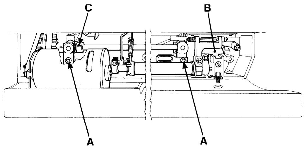
Undo both screws (A) underneath the base plate and shift the motor until the required tension is obtained.
Comments
The motor is driven by direct current (DC) 24V , whereby the demands on insulation clearance are less than by 220V .
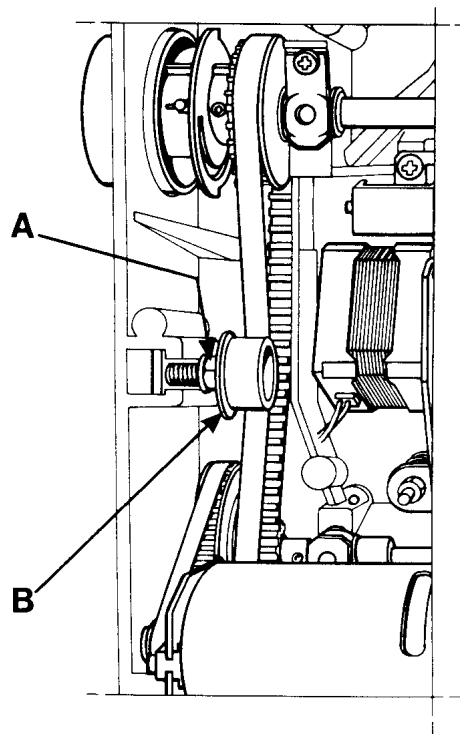
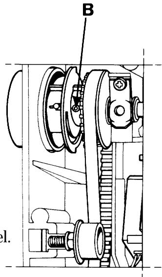
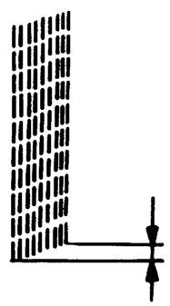
The cog belt, long
Requirements
The belt tension should not be so loose that it permits slipping when the machine is locked and the foot control is depressed.
A tighter tension makes more noise.
The belt must not be damaged.
Adjustment
Loosen the nut (A) by means of a 10mm fixed spanner and shift the belt tension roller belt tension roller (B) until the required tension is obtained.
Tighten the nut.
ELECTRONICS
Wiring Diagram
CONNECTING EXTERNAL UNITS TO DRIVEBOARD
1 THREAD TENSION MOTOR
2 PRESSER FOOT SWITCH
3 LAMP/LENGTH SENSOR
4 LAMP
5 MAIN MOTOR
6 NEEDLE MOTOR
7 LOW THREAD INDICATOR
8 FEEDING MOTOR
9 SIDE MOTION MOTOR
BE SURE THAT CABLES TO DRIVE-BOARD ARE CORRECTLY CONNECTED, BEFORE SWITCHING ON MAIN SUPPLY
MODEL 1050/1090
MODEL 1070
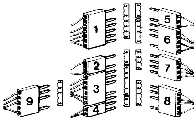
MODEL 1100/1200/#1
Service cassette, model 1100, 1200
To facilitate the control and setting of the different functions of the machine there is a service casette.
This is used together with the service mode of the machine.
Handling
-Insert the service cassette into the cassette terminal in the front cover.
- Get into the service mode of the machine by holding the back feeding button and (-) stitch length pressed while turning on the main switch.
Service program, model 1050, 1070,1090
To facilitate the control and setting of the different functions of the machine there is a service program.
Handling
- Get into the service program of the machine by holding the back feeding button and (-) stitch length pressed while turning on the main switch.
Functions on the service casette 1100, 1200
Key 1 Shown in the right display.
Number of the program memory.
Which cassettes the program memory contains.
Which cassette is in the machine.
Check can be made that the machine reads the correct casette being inserted.
The letter of the cassette has to be in accordance with the one shown on the display.
Key 2 Display test where all symbols light up on both displays.
Key 4 Check that the arm shaft sensor (stop right function) works. The latter looks after when the step motors have to be reset, it reads the speed and the stop right functions.
A square is shown in the right display.
If this square jumps around clockwise between 4 positions, 2 up and 2 down while "slowly" pulling the machine around with the handwheel, the function is correct.
Key 5 Is used when setting the step motor of the sewing head.
The step motors set themselves into the calibration position.
Setting no 5 (P.26).
Key 6 Is used when setting the step motor of the sewing head. Setting no 5 (P.26).
The setting of the needle in relation to the presser foot.
Setting no 6 (P.27).
Key 7 Is used when setting the step motor of the thread tension. Setting no 13 (P.33).
The step motor now takes its calibration position.
Key 8 Is used when checking the setting above.
The thread tension pulley shall set at 5.5 (=normal position).
Key 9 Is used when pre-setting the step motor of the guide. Setting no 21
(P.41). The step motor now takes its calibration position.
Key 11 Is used when setting the stitch length balance. Setting no 20 (P.39-40).
The feed dog shall stand still (0-feeding).
Key 12 Is used when setting the stitch length balance. Setting no 20 (P.39).
1100 The machine now sews a service buttonhole where both columns should have the same length.
Key 12 Is used when setting the stitch length balance. Setting no 20 (P.40).
1200 The machine now sews stitch L-48 (rabbit) of the L-casette.
Key 13 Is used when setting the stitch length balance. Setting no 20 (P.39-40).
The machine sews the signs B,C,D,P,S,T,8.
Key 14 Is used when setting the stitch length balance. Setting no 20 (P.39-40).
The machine now sews stitch A38 which should have a rectangular aspect.
NOTE! Not mentioned keys are not used at service or are without function.
Functions of the service program 1070
Key 1 Code letter of the program memory.
Key 2 Display test where all symbols light up on the display.
Key 4 Check that the arm shaft sensor (stop right function) works. The latter looks after when the step motors have to be reset, it reads the speed and the stop right functions. The function is correct if numbers 1-4 are shown in the right part of the display, while the handwheel is turned around slowly.
Key 5 Is used when setting the step motor of the sewing head. The step motors set themselves into the calibration position. Setting no 5 (P. 26).
Key 6 Is used when setting the step motor of the sewing head. Setting no 5 (P. 26). The setting of the needle in relation to the presser foot. Setting no 6 (P. 27).
Key 7 Is used when pre-setting the step motor of the guide. Setting no 21 (P. 41). The step motor now takes its calibration position.
Key 37 Is used when setting the stitch length balance. Setting no 20 (P. 37). The machine now sews the signs C, D, B, P, S, T, 8.
Key 40 Is used when setting the stitch length balance. Setting no 20 (P. 37. The feed dog shall stand still (0-feeding).
Key 41 Is used when setting the stitch length balance. Setting no 20 (P. 37). The machine now sews the stitch 41 which shall have a rectangular look.
NOTE! Not mentioned keys are not used at service or are without function.
Functions of the service program 1050
Key 1 Code letter of the program memory.
Key 2 Display test where all symbols light up on the display.
Key 4 Check that the arm shaft sensor (stop right function) works. The latter looks after when the step motors have to be reset, it reads the speed and the stop right functions. The function is correct if numbers 1-4 are shown in the right part of the display, while the handwheel is turned around slowly.
Key 5 Is used when setting the step motor of the sewing head. The step motors set themselves into the calibration position. Setting no 5 (P. 26).
Key 6 Is used when setting the step motor of the sewing head. Setting no 5 (P. 26). The setting of the needle in relation to the presser foot. Setting no 6 (P. 27).
Key 7 Is used when pre-setting the step motor of the guide. Setting no 21(P. 41). The step motor now takes its calibration position.
Menu D+ Is used when setting the stitch length balance. Setting no 20 (P. 36).
Key 6 The feed dog shall stand still (0-feeding).
Menu D+ Is used when setting the stitch length balance. Setting no 20 (P. 36).
Key 7 The machine now sews the stitch D7 which shall have a rectangular look.
NOTE! Not mentioned keys are not used at service or are withoutfunction.
Functions of the service program 1090
Key 1 Code letter of the program memory.
Key 2 Display test where all symbols light up on the display.
Key 4 Check that the arm shaft sensor (stop right function) works. The latter looks after when the step motors have to be reset, it reads the speed and the stop right functions. The function is correct if numbers 1-4 are shown in the right part of the display, while the handwheel is turned around slowly.
Key 5 Is used when setting the step motor of the sewing head.
The step motors set themselves into the calibration position. Setting no 5 (P. 26).
Key 6 Is used when setting the step motor of the sewing head. Setting no 5 (P. 26).
The setting of the needle in relation to the presser foot. Setting no 6 (P. 27).
Key 7 Is used when pre-setting the step motor of the guide. Setting no 21(P. 41).
The step motor now takes its calibration position.
Key 24 Is used when setting the stitch length balance. Setting no 20 (P. 38).
The machine sews the signs C, D, B, P, S, T, 8.
Key 38 Is used when setting the stitch length balance. Setting no 20 (P. 38).
The feed dog shall stand still (0-feeding).
Key 39 Is used when setting the stitch length balance. Setting no 20 (P. 38).
The machine now sews the stitch 39 which shall have a rectangular look.
NOTE! Not mentioned keys are not used at service or are without function.
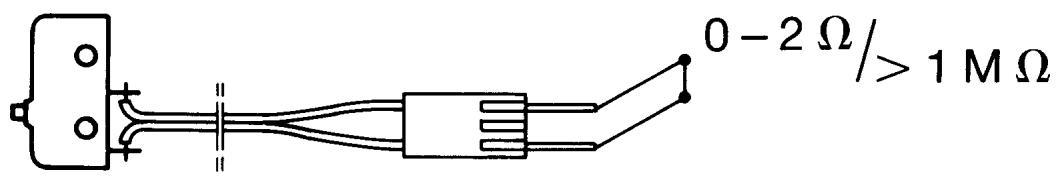
Switch for the presser foot lift
In the sewing head there is a little switch that close when the presser foot is being lifted.
Then you cannot sew and a humming sound and flashing displays warns.
If there is anything wrong with the switch the machine can sew.
The function of the switch can be checked with a multi-range instrument at the lowest - range by measuring between the two pins of the plug.
Lifted presser foot = 1
Lowered presser foot = 0
If the values are correct the fault is inside the circuit board or the connection between the circuit board and the LCD board.
(Exceptionally the fault can also be inside the LCD board).
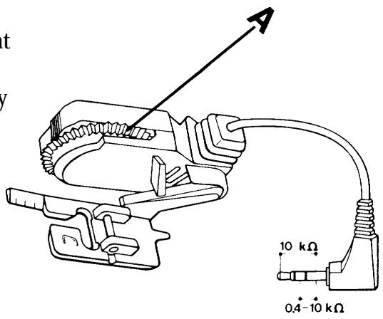
Buttonhole meter
Check the functions according to directions for use.
Inside the buttonhole meter there is a potentiometer that is influenced by the measuring wheel (A).
The function of the buttonhole meter can be checked by a multi-range instrument (-measuring).
When the measuring wheel (A) is turned a value between 0.4 - 10k is obtained.
If the values are correct the fault is inside the circuit board or the connection between the circuit board and the LCD board.
(Exceptionally the fault can also be inside the LCD board).
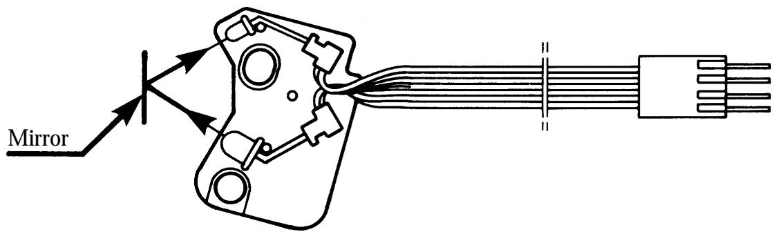
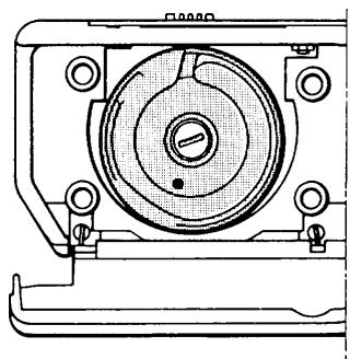
Lower thread indicator
When the lower thread is almost at an end the machine gives a warning signal and a bobbin flashes on the information display.
The lower thread indicator consists of an IR-diode that is reflected against a mirror on the hub of the bobbin case, if the upper part of the bobbin is out of thread, and is received by a photo transistor.
If the indicator does not work, it may be due to the indicator or the bobbin case being dirty which makes it impossible for the IR-light to pass.
If the indicator still doesn't work it should be replaced.
The fault may also be found on the circuit board, its connections or in some cases on the LCD board.
You can check the indicator if you connect it to the circuit board (but don't mount it) and hold a mirror in front of it.
Photo transistor
(receiver)
IR-diode
(emitter)
Step motor thread tension
The upper thread tension of the machine is automatically adjusted by a unipolar step motor with 7.5 steps.
If the adjustment doesn't work inspite of settings no 11 and no 12 being checked by means of the service casette, the step motor or the thread tension device compl. should be replaced.
If the adjustment still doesn't work the fault is in the circuit
board, its connections, or in some rare cases on the LCD board.
Step motor sewing head
The zigzag movement of the needle is done by a bipolar step motor with 7.5 steps.
If there is not any zigzag movement of the machine despite checking setting no 5 by means of the service casette/program. Check the circuit board by means of gauge 412 02 56-01 (also check that the connections are undamaged).
If the zigzag movement still doesn't work dismount the sewing head and check easy running.
If this is allright try a new sewing head or step motor.
In some rare cases the fault can be in the LCD board.
The step motor of the guide (feeding)
The setting of the feeding direction from forward to backward between long and short stitches is done by a bipolar step motor with 7.5 steps.
If this setting doesn't work despite checking of setting no 21by means of the service casette.
Check the circuit board by means of gauge 412 02 56-01.
(Also check that the connections are undamaged).
If the adjustment still doesn't work dismount the feeding guide compl. and check easy running.
Is this alright try a new feeding guide or step motor.
In some rare cases the fault can be in the LCD board.
Step motor side feeding
The side feeding of the feed dog is created by a bipolar step motor with 7,5 steps.
If the side feeding of the feed dog does not work, check the pre-setting of the step motor, the free-running of the feeding device and the sideways setting of the feed dog.
If the side feeding still does not work, check:
- the cable connection of the step motor to the circuitboard,
- the step motor,
- the smooth-running of the feeding movement,
- the circuit board,
- the LCD board.
Transformer 1050, 1070, 1090
The function of the transformer can be checked with gauge 412 02 56-01.
Electronics boards 1050
The machine has one circuit board and one foil keyboard.
The transformer board is part of the transformer compl.
Electronics boards, 1070, 1090
The machine has 2 different boards and 2 foil keyboards.
The transformer board is part of the transformer compl.
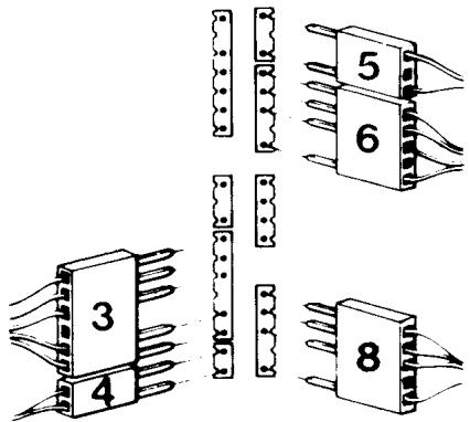
Circuit board 1050, 1070, 1090
The circuit board is on the front side in the arm and contains among other things:
- Components to stabilise the voltage,
- Main motor driving,
- Driving of the step motor of the sewing head,
- Driving of the step motor of the guide,
- LCD-display and its driving,
- Arm shaft sensor,
- Computer, memory,
- Light.
Guide board 1090
The guide board is in the front cover and contains light emitting diodes and a micro chip.
Foil keyboard 1050
The machine has one foil keyboard.
-which is placed in the upper part of the front cover with among other things buttons for stitch width and stitch length adjustment.
Foil keyboard 1070, 1090
The machine has 2 foil keyboards.
-one of them (elliptically) is placed in the upper part of the front cover with among other things buttons for stitch width and stitch length adjustment.
-one of them is placed into the right part of the front cover with buttons for decorative stitches and the sewing advisor.
Main motor 1050, 1070, 1090
The main motor is a 24 volt permanent magnet motor that consumes 60W at maximum speed. If the main motor doesn't work when the foot control is pressed, try:
1) New foot control
2) New motor (only connect to circuit board at check)
3) New circuit board
4) New transformer (if the machine doesn't work at all)
1100, 1200
Transformer
The function of the transformer can be checked with gauge 412 02 56-01.
Electronics boards
The machine has 4 different boards and one foil keyboard. The transformer board is part of the transformer compl.
Circuit board
The circuit board is on the front side in the arm and contains among other things:
- Components to stabilise the voltage,
-Main motor driving,
-Driving of the step motor of the sewing head,
-Driving of the step motor of the guide,
-Driving of the step motor of the thread tension,
-Driving of the step motor of the side motion, applies for model 1200,
-Arm shaft sensor,
-Buttonhole meter,
-Lower thread indicator - Switch for the presser foot lifting,
-Light.
LCD board
The LCD board is in the front cover and contains among other things 2 LCD displays and the driving for these, contacts (carbon pressure), for the keys beneath the scale, the computer, the computer memories, and a warning buzzer.
The key functions are checked by means of the service cassette.
Guide board
The guide board is in the front cover and contains among other things light emitting diodes and contacts (carbon pressure) for the keys to the sewing guide.
Check by means of the service casette.
Foil keyboard
The foil keyboard is in the bottom of the cassette terminal of the front cover and contains keys from the cassette and a sensor for the coding of the cassette.
In the bottom of the casette terminal there is a code spring that presses on those by means of the coding of the casette.
Check by means of the service cassette.
Main motor
The main motor is a 24 volt permanent magnet motor that consumes 60W at maximum speed. If the main motor doesn't work when the foot control is pressed, try:
1) New foot control
2) New motor (only connect to circuit board at check)
3) New circuit board
4) New transformer
The angle of view of the LCD displays
To get a clear picture on the displays independent of how you sit or how tall you are you might have to adjust the angle of view.
This is done by turning the little pulley in the edge of the cassette terminal.
SETTING INSTRUCTIONS
The best and fastest results are obtained if you make the settings in the following order when servicing.
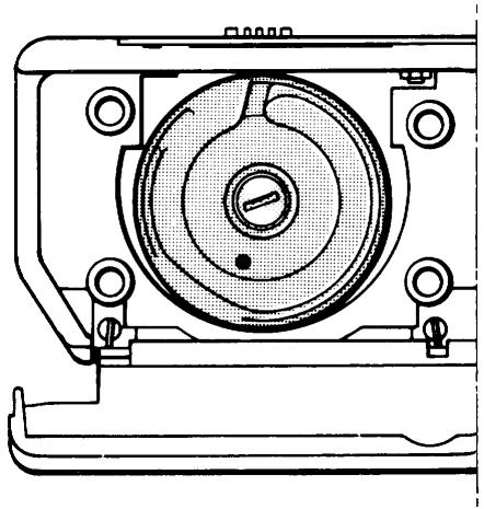
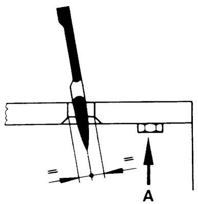
1 The hook gear
Tangential play
Requirements
Lock the handwheel and turn the driver forward and back again.
The gear must not be completely tight but the play should be as small as possible.
Adjustment
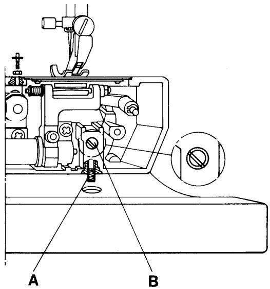
Remove the stitch plate. Loosen the stop screw (A) and turn the shaft (B) until the required play is obtained.
Comment I
The shaft is journalled eccentrically and must always be set so that the screwdriver slot is to the left of the centre of the hole (see illustration).
The same play in the hook gear can be obtained by turning the shaft a half turn but the hook will then lie eccentrically in relation to the hook cover.
The shaft is also shiftable.
Check therefore that the gap between the hook cover and the driver has not been altered (P.24).

Comment II
Too little play results in slow running and increased wear.
Too big play results in noise and risks missing stitches.
Thereafter adjust:
Gap between the hook cover and the driver, (P.24).
Timing of the hook in relation to the needle, (P.30).
Gap between hook and the needle, (P.28).
Setting the stitch plate in relation to the needle, (P.29).
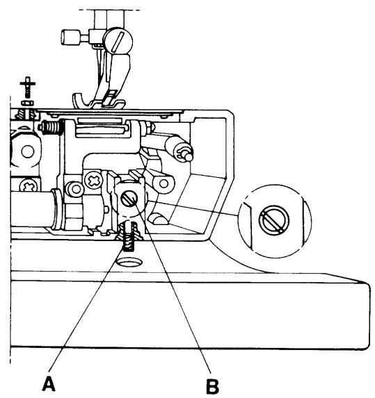
2 The gap between the hook cover and driver
The hook cover is mounted on four fixed supports in the arm. On those two on the right there are distance washers.
The distance between the hook cover and the driver should be so big that the thread can pass freely on both sides of the hook.
Requirements
The gap between the hook cover and the driver should be such that when the hook is exchanged for the gauge 411 16 49-01, the gauge should have no play but must be turnable.
Adjustment
Undo the screws which hold the hook cover.
Exchange the hook for the gauge and replace the hook cover.
Undo the screw (A) for the hook shaft and shift the shaft (B), without turning it, to the correct position.
Tighten the screw.
Comment
The shaft (B) is eccentrically mounted and if it is turned it will affect the play in the hook gear.
Thereafter check:
The gap between the hook and the needle (P.28).
Setting of the stitch plate in relation to the needle, (P.29).
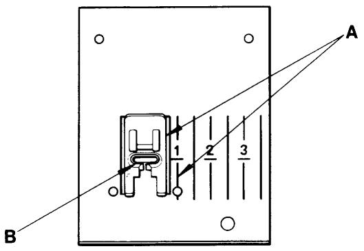
3 I. Presser foot, parallelism to the stitch plate
Requirements
The presser foot shall be parallel to the marking lines (A) on the stitch plate.
Adjustment
Undo the screw (B) and turn the presser foot until requirement is obtained.
NOTE! This setting must be correct for all the other settings in the sewing head.
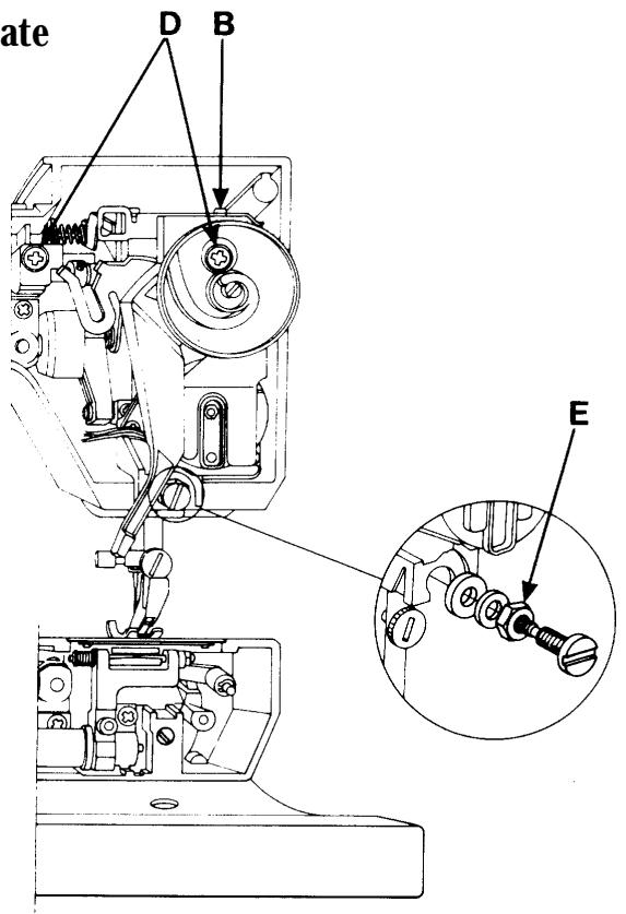
4 II. Setting the presser foot at right angles to the feeding direction.
Requirements
The sewing head should be set in such a way that the needle hole of the presser foot is in accordance with the needle hole of the stitch plate.
Adjustment
Undo the screws (D) (turn the pulley for the presser foot pressure so that the right one becomes available) and the nut (E).
Shift the sewing head until requirement is obtained.
Tighten the screws (first the left one) and the nut.
Comments
On the underneath of the buttonhole foot there is a guide, which steers the fabric.
If the position of the presser foot is not correct in relation to the needle, the distance between the columns will be affected.
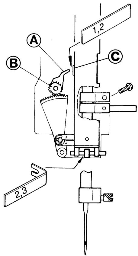
5 Setting of the stepmotor of the sewing head
Requirements
Set the needle at the upper turning position. The needle shall always get to the central position, when the main switch is turned on repeatedly.
The distance between the zig-zag bearing of the needle bar frame and the stop lug shall be equal on both sides 2,3mm .
Adjustment
- Remove the sewing head from the machine (p.52) but let the cables be connected to the circuit board.
- Place the service cassette into the front cover.
- Enter the service mode of the machine by pressing the reverse feeding button and (-) stitch length button while turning on the main switch.
- Turn the handwheel until the feed dog reaches its highest position.
- Press button no(5) on the service casing/program (= calibration position).
- Check the distance (= 1,2mm) between the calibration wing (A) and the calibration stop (C) with the distance gauge 412 27 60-01.
Adjust by loosening the screw of the calibration wing (A) and set distance. - Press button no(6) on the service casing/program (= centre position).
- Check the distance(2,3mm) between the zig-zag bearing of the needle bar frame and the stop lug with distance gauge 412 27 60-01).
- Adjust by undoing the screw of the cog wheel (B) and turn the cog wheel until the correct distance is obtained.
- Mount the sewing head into the machine, (P.54).
Thereafter set:
Setting the presser foot at right angles to the feeding direction (P.25).
The gap between the hook and the needle (P.28).
Setting the stitch plate in relation to the needle (P.29).
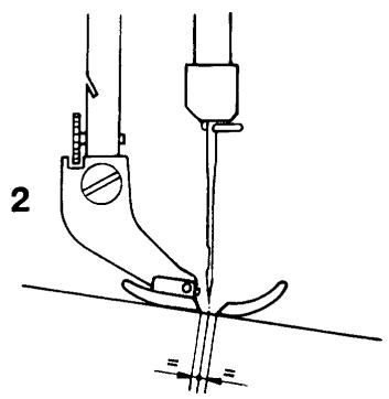
6 Setting of the needle in relation to the presser foot
Requirements
When the machine is set at straight stitching centre position, the needle bar shall be set in such a way that a needle 90 passes through the centre of the needle hole in the presser foot.
1 = seen from the front
2 = seen from the side
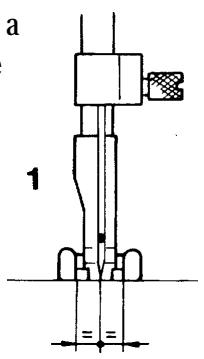
Adjustment
Switch on the mainswitch
Keep the machine set at straight stitching centre position (alt. service mode/program button no 6).
Undo the screws (A) by means of an adam key 412 27 65-01.
Put the adam key into the hole (B) and move the needle bar until requirement obtains.
Tighten the screws.
Check the setting by switching mains on and off a couple of times.
Thereafter check:
The gap between the hook and the needle (P.28).
Setting of the stitch plate in relation to the needle (P.29).
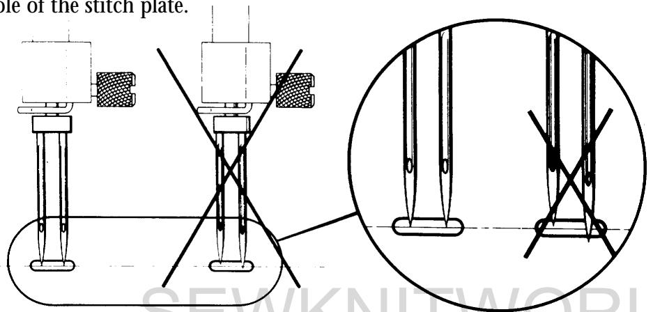
7 The gap between the hook and the needle
Requirements
Set the machine for straight stitching.
Insert a new needle 90.
Lay the back of the machine on the table.
Turn the handwheel until the tip of the hook gets behind the needle (see fig.).
Press the hook against the driver.
The gap between the needle and the tip of the hook should be as little as possible.
Comments
To enable the thread loop to go between the hook and the driver a certain axial play must be possible.
Contact between needle and hook can
therefore result and cause a sound, which can
be heard when the machine is running without thread.
This contact damages neither the hook nor
the needle, as long as a needle with a groove
according to system 705H is used.
Adjustment
The position of the needle is adjusted by moving the sewing head in the feeding direction.
Loosen the nut (A).
Shift the sewing head by turning the lower
adjustment nut (B) until the required position is reached.
Hold the adjustment nut in position and tighten
the locking nut.
Check the setting.
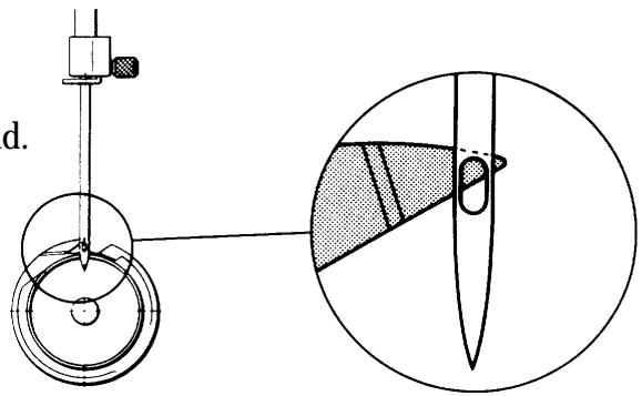
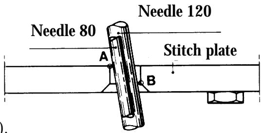
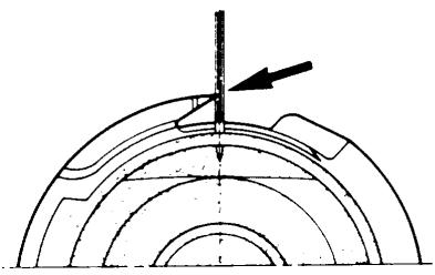
8 Setting the stitch plate in relation to the needle (in the feeding direction)
Requirements
The stitch plate must be centred in relation to the needle in the feeding direction.
Adjustment
Insert a new needle 90.
Adjust the stitch plate to the needle.
Loosen the nut (A) on the underneath of the arm.
Adjust the stitch plate to the correct position.
Fix the stitch plate by hand and tighten the nut.
Comments
The gap between the centre line of the needle and the flat part of the needle base varies with the thickness of the needle.
To enable the needle 120 to move freely from the front edge of the underneath of the needle hole, set the stitch plate so that the needle 90 is between points (A) and (B).
Needle 80 will lie slightly behind the centre of the needle hole.
NOTE! The angled position of the needle.
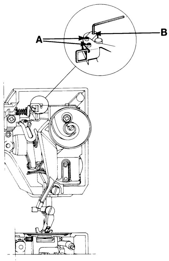
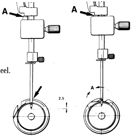
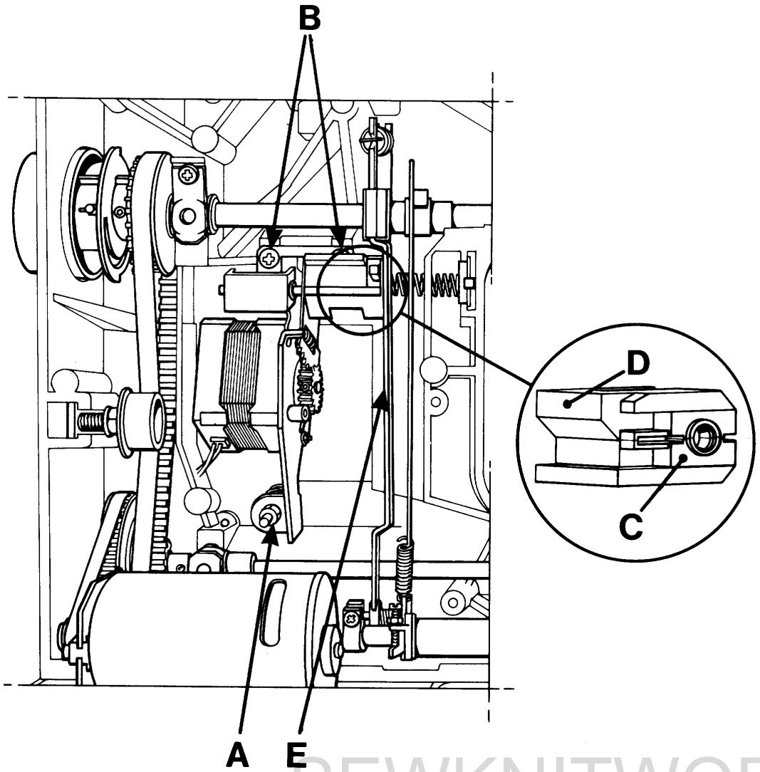
9 Timing of the hook in relation to the needle
Requirements
Switch on main switch, and set the machine for straight stitching.
As the needle is moving upward the tip of the hook should pass the centre line of the needle when the needle is 2,5mm above the lower turning position (the distance for forming the loop).
Check
Remove the rear cover, the lamp cover and the handwheel. Remove the hook cover.
- Turn the arm shaft by means of the driver pin so that the needle reaches its lower turning position.
- Place the setting gauge 411 17 52-01 on the needle bar until the spring-loaded stud (A) touches the needle bar frame and tighten the screw.
- Move the needle up by pulling the short cog belt in toward the machine until the spring-loaded stud rests against its stop in the gauge, according to the figure on the right.
The needle has now moved up 2,5mm from the turning position (the distance for forming the loop).
Hold the hook back so that it is pushed downward and backward. The tip of the hook shall now be in the centre of the needle.
Adjustment
-Remove the pointed screw (B) and undo the other two screws.
-Repeat the checking points 1,2 and 3.
- Hold the arm shaft and turn the hook and the driver by pulling the short cog belt in toward the machine until the tip of the hook comes in front of the centre of the needle.
When tightening the screws on the pulley, the pointed screw should change places with the black screw that was unscrewed earlier. Otherwise the pointed screw might retake its earlier position.
Mount the hook cover, the rear cover, the lamp cover and the handwheel. (Note! the position of the handwheel in the screen).
Comments
By moving the needle all the time by means of the short cog belt, this will counteract any possible play between the long cog belt and the cog wheels.
NOTE!
The axial play of the arm shaft might change when loosening the screws.
Maximum play may be 0,05 ~mm .
10 The needle height
Requirements
Set the machine for zig-zag, right-hand position, Setting 6mm stitch width.
Move the needle upward by pulling the short cog position belt in toward the machine and at the same time holding the hook downward, backward.
When the tip of the hook reaches the centre line of the needle, the underneath of the tip should be in line with the top edge of the needle eye.
Comment I
The gap between the tip of the hook and the needle eye is influenced by the timing of the hook in relation to the needle. Therefore check the timing according to the previous page before making any adjustment.
Comment II
The gap between the tip of the hook and the needle eye, with the needle at the centre position (1.5mm) is the starting measurement but as this is difficult to estimate, use the corresponding measurement with the needle at the right-hand position instead.
Adjustment
Set the machine for zig-zag, right-hand position, 6mm. Move the needle upward by pulling the short cog belt in toward the machine until the tip of the hook reaches the centre line of the needle.
Push the hook downward and hold it, so that the catch of the hook rests against the left side of the slot in the driver. Loosen the screw (A).
Move the needle bar in such a way until the underneath of the tip of the hook is in line with the top edge of the needle eye.
Tighten the screw (A).
NOTE!
Check that the needle eye is at right angles to the hook by fitting a twin needle and observing the needle positions in the needle hole of the stitch plate.

Thread tension
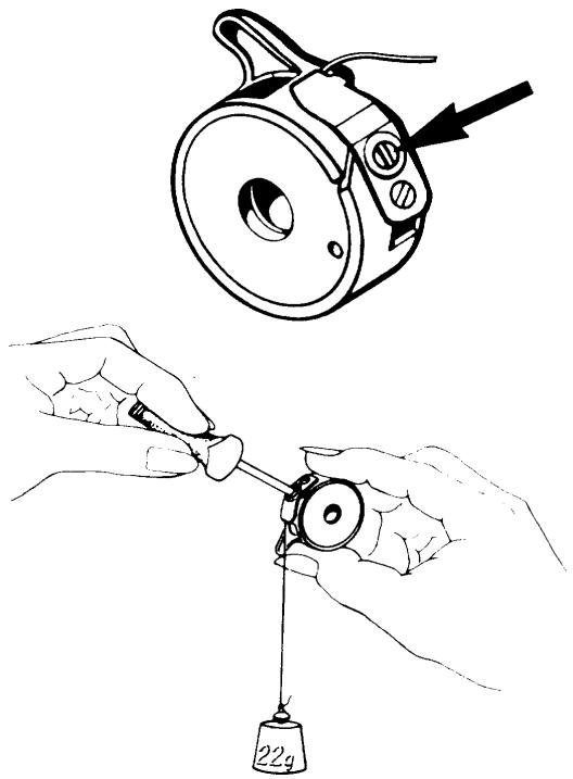
11 The thread tension of the bobbin case
Requirements
The thread tension spring of the bobbin case shall give a thread resistance of 18 - 22g when pulling the tread slowly.
Check weight 22g ref.n 412 15 83-01.
Adjustment
Remove any loose pieces of thread collected under the thread tension spring. Attach the thread to the weight and hold the bobbin case, letting the thread hang vertically in direction of the bobbin case finger. When the thread tension is correctly set the weight shall pull the thread slowly from the bobbin case. Adjust the thread tension by means of the screw.
12 Upper thread tension
Requirements, model 1050/1070/1090
When the machine is set at straight stitching resp. zig-zag, a correct take-up should be obtained, when the catch of the thread tension pulley (5,5) is right in front of the index.
Requirements, model 1100/1200
When the sewing guide of the machine is set at non elastic normal and straight stitching resp. zig-zag, a correct take-up should be obtained, when the catch of the thread tension pulley (5,5) is right in front of the index.

Comment 1
The sewing guide adjusts the thread tension to the fabric resp. to the sewing at which the machine is set. This is done by means of the computer and the step motor of the machine.
Comment 2
The thread tension that is set now is to be regarded as a general indication. This general indication can be risen and lowered by means of the thread tension pulley and remains as long as the main switch is on.
Adjustment
Remove the rear cover, (P.44).
At the side of the thread tension dial there is an adjustment screw (A) for the setting of the upper thread tension.
This is accessible from the rear by means of a screwdriver..
Set the catch of the thread tension dial in the middle of the index.
When test sewing with normal fabric and thread turn the adjustment screw until the correct take-up is obtained for straight stitching and zig-zag.
13 Setting the thread tension of the step motor
Requirements
The thread tension pulley shall always be at its starting position (5,5) when the main switch is switched on and off repeatedly.
Adjustment
- Remove the front cover (P.35) but leave the cables connected to the circuit board.
- Dismount the thread tension compl. (P.39), but leave the cable connected to the circuit board.
-Insert the service casing into the front cover.
-Get into the service mode of the machine by pressing the reverse feeding and (-) stitch length buttons while switching on the main switch. - Loosen the screw in the cog wheel (B) of the step motor.
- Turn the thread tension pulley to 0.
- Press button n 7 on the service cassette.
- Tighten the screw.
- Check according to requirements.
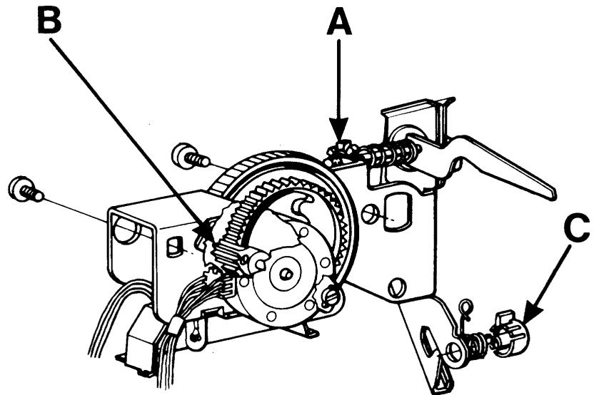
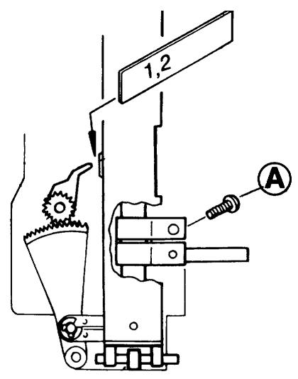
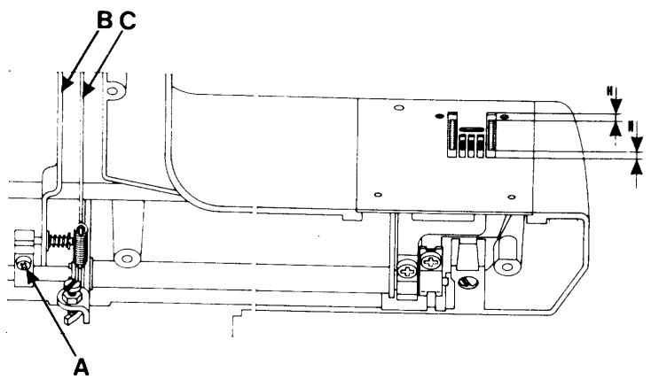
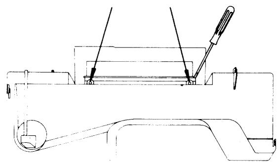
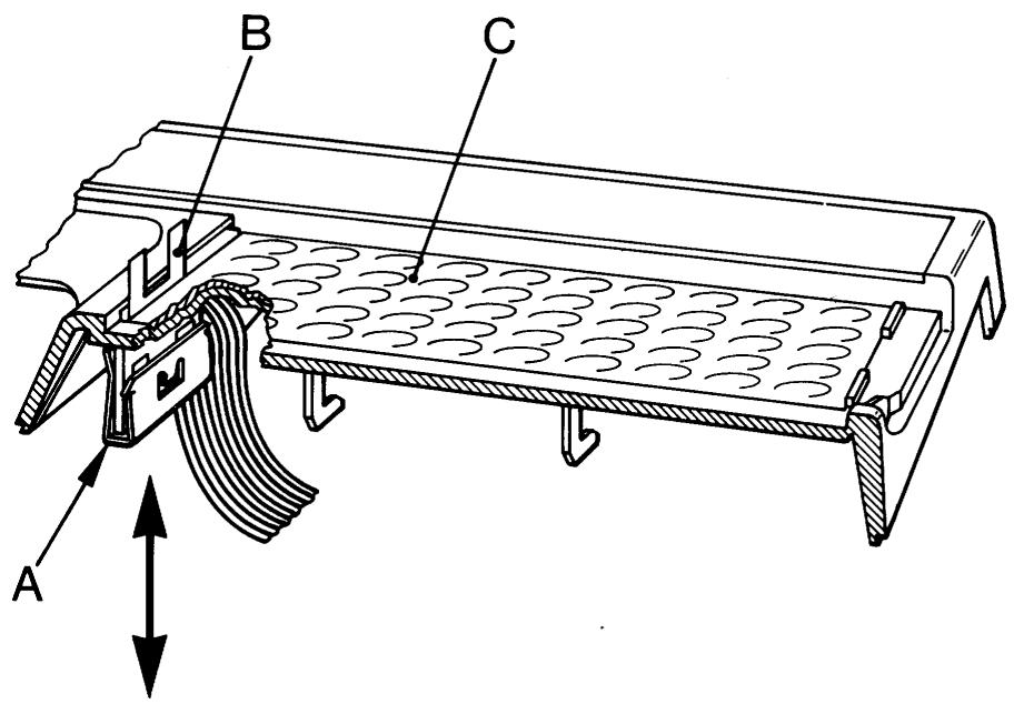
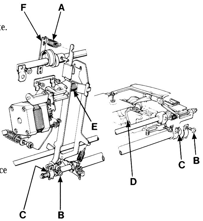
14 The setting of the thread take-up spring
Requirements
The casing (C) should be set in such a way, that the thread take-up spring has finished its movement when the needle eye reaches the fabric after a completed stitch.
Check at straight stitching 2.5mm in fine fabric.
Adjustment
The stop in the adjustment casing, i.e. the limitation of the movement of the spring, can be adjusted by means of a screwdriver, which should be applied at the upper part of the casing.
Exchange of the thread tension device.
(P.52).
The setting of the feed dog
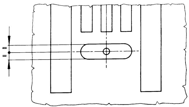
15 I The parallelism of the feed dog
Requirement A
The feed dog should be parallel with the grooves in the stitch plate.
Adjustment
Set the feed dog in its highest position.
Remove the stitch plate and loosen the screws (A) which hold the feed dog, fit the stitch plate and adjust the feed dog until it lies parallel with the grooves in the stitch plate.
Then remove the stitch plate without moving the feed dog.
Tighten the screws and check that the feed dog is positioned correctly in the stitch plate.
16 II The sideways setting of the feed dog
Requirements B, model 1050/1070/1090/1100
The feed dog should move freely in the grooves of the stitch plate (sideways).
Requirements B, model 1200
At side feeding the feed dog should move
freely in both side positions
(goes for all 4 feed dog rows).
Adjustment
Turn the nut (B) until requirements is reached.
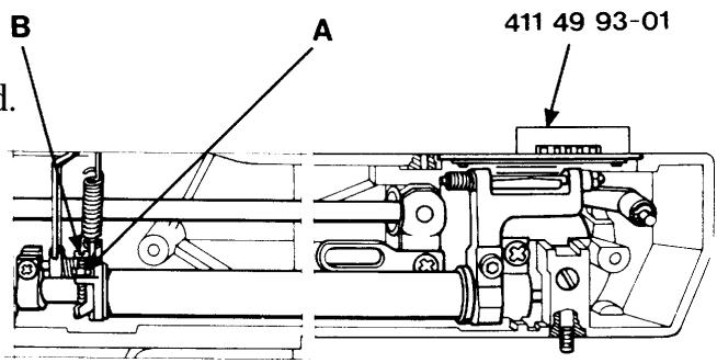
17 III The feed dog height
Requirements
The feed dog should be between
1.0 and 1.1mm above the stitch plate
when the feed dog is
in its highest position.
Adjustment
Set the feed dog at its highest position.
Put setting gauge 411 49 93-01 above the feed dog.
Loosen nut (A) and turn the screw (B) until requirements is reached.
18 IV The lengthwise movement of the feed dog
Requirements
The feed dog must not strike against the stitch plate when the machine is set at maximum stitch length and speed.
Adjustment
Set the machine at stitch length 0mm and the feed dog at its highest position. Loosen the screw (A) and shift the feed dog until it comes in the middle of the stitch plate.
Tighten the screw.
Check according to requirements.
NOTE!
Check that the stitch setting fork (B) is parallel with the connecting rod (C) after tightening.
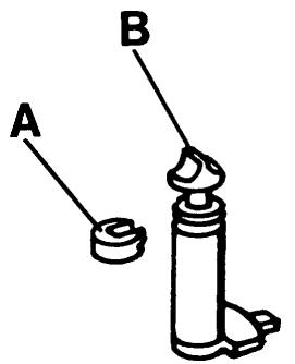
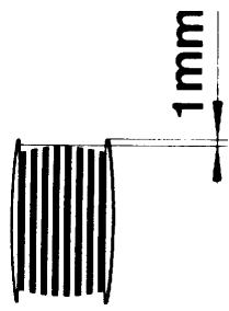
19 The bobbin-winding device
Limiting when bobbin-winding
Requirements
When bobbin-winding the machine shall stop when the bobbin is full with thread up to approx. 1mm from the edge of the bobbin.
Adjustment
Loosen the locking ring (A) by means of a tool.
Thereafter turn the scanner (B) until you switch off when there is an adequate amount of thread on the bobbin (see illustration).
After the adjustment the scanner is secured from being turned by means of the locking ring.
20 The balance of the stitch length - model 1050
Requirements
A Both the columns of the buttonhole shall have the same tightness.
B The machine shall sew a pattern according to the symbol.
C The machine shall sew stitch D7 which is to have a rectangular look.

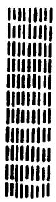
D7
Check
- Get into the service program of the machine by pressing the reverse feeding and (-) stitch length buttons while turning on the main switch.
- Select menu D.
- Press button no 7. The machine will now sew a pre-programmed stitch D7 whose left and right side must not differ in length with more than 2mm the (see illustration).
Coarse adjustment
Select menu D.
Press button no 6 (=feeding 0).
Turn the nut (A) until the feed dog comes to a stand still when the foot control is pressed down.
Fine adjustment
Select menu D.
Press button no 7 and turn the nut (A) until the machine sews a stitch D7 according to illustration.
Check that both the columns of the buttonhole have the same tightness.
20 The balance of the stitch length - 1070
Requirements
A Both the columns of the buttonhole shall have the same tightness.
B The machine shall sew a pattern and letters according to the symbol.
C The machine shall sew stitch 41 which is to have a rectangular look.
41
Check
- Get into the service program of the machine by pressing the reverse feeding and (-) stitch length buttons while turning on the main switch.
- Press button no 41.
The machine will now sew a pre-programmed stitch 41 whose left and right side must not differ in length with more than 2mm the (see illustration).
- Press button no 37.
The machine will now sew the signs C, D, B, P, S, T, 8 which should have the correct aspect.
Coarse adjustment
Press button no 40 (=feeding 0).
Turn the nut (A) until the feed dog comes to a stand still when the foot control is pressed down.
Fine adjustment
Press button no 41 and turn the nut (A) until the machine sews a stitch 41 according to illustration.
Check the aspect of the following signs:
C, D, B, P, S, T, 8 and that both columns of the buttonhole have the same tightness.
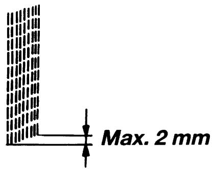
20 The balance of the stitch length - 1090
Requirements
A Both the columns of the buttonhole shall have the same tightness.
B The machine shall sew a pattern and letters according to the symbol.
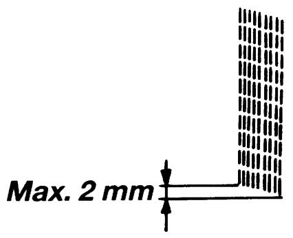
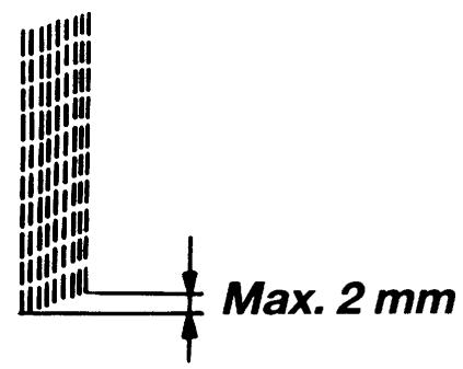
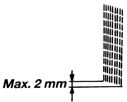
C The machine shall sew stitch 39 which is to have a rectangular look.

39
Max. 2 mm
Check
- Get into the service program of the machine by pressing the reverse feeding and (-) stitch length buttons while turning on the main switch.
- Press button no 39.
The machine will now sew a pre-programmed stitch 41 whose left and right side must not differ in length with more than 2mm the (see illustration).
- Press button no 24.
The machine will now sew the signs C, D, B, P,S,T,8 which should have the correct aspect.
Coarse adjustment
Press button no 38 (=feeding 0).
Turn the nut (A) until the feed dog comes to a stand still when the foot control is pressed down.
Fine adjustment
Press button no 39 and turn the nut (A) until the machine sews a stitch 39 according to illustration.
Check the aspect of the following signs:
C, D, B, P, S, T, 8 and that both columns of the buttonhole have the same tightness.
20 The balance of the stitchlength 1100
Requirements
A Both the columns of the buttonhole shall have the same tightness.
B The machine shall sew a pattern and letters according to the symbol.
C The machine shall sew stitch A 38 of the A-casette which is to have a rectangular look.
A 38

Check
-Insert the service cassette into the front cover.
-Get into the service mode of the machine by pressing the reverse feeding and (-) stitch length buttons while turning on the main switch.
-Press button no 14 on the service casing.
The machine will now sew stitch A 38 of the
A-casette whose left and right side must not differ in length with more than 2mm the (see illustration). The length of the stitch is pre-programmed.
-Press button n13.
The machine will now sew the signs C,D,B,P,S,T,8 which should have the correct aspect.
Coarse adjustment
Press button n11 on the service casing (=feeding 0). Turn the nut (A) until the feed dog comes to a stand still when the foot control is pressed down.
Fine adjustment
Press button n12 on the service casing and turn the nut (A) until the machine sews a service buttonhole whose columns are of the same length (see illustration).
Check the aspect of the folling signs: C,D,B,P,S,T,8 and that the columns of the buttonhole have the same tightness.
20 The balance of the stitch - 1200
Requirements
The machine shall sew patterns and letters according to the symbol.


NOTE!
When checking and adjusting the stitch length balance test sewing is to be carried out on a simple cotton cloth with pads (Stitch'n tear) and a thin and smooth lower thread (=normal synthetic thread) is to be used. Otherwise the balance of the omnigram stitches might be influenced.
Check
-Insert the service cassette into the front cover.
-Get into the service mode of the machine by pressing the reverse feeding and (-) stitch length buttons while turning on the main switch.
-Press button no 12 on the service casing.
The machine will now sew stitch L 48 (the rabbit) of the L-casette.
- The chin of the rabbit must not show much difference in height.
-Press button n13.
The machine will now sew the signs C,D,B,P,S,T,8 which should have the correct aspect.
Coarse adjustment
Press button no 11 on the service casing (=feeding 0). Turn the nut (A) until the feed dog comes to a stand still when the foot control is pressed down.
Fine adjustment
Press button no 12 on the service cassette and turn the nut (A) until the machine sews stitch L-48 according to illustration.
Check the aspect of the folling signs: C,D,B,P,S,T,8 and that the columns of the buttonhole have the same tightness.
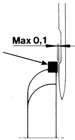
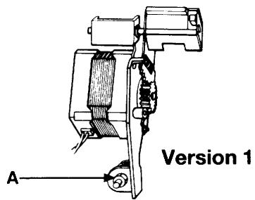
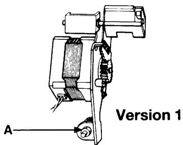
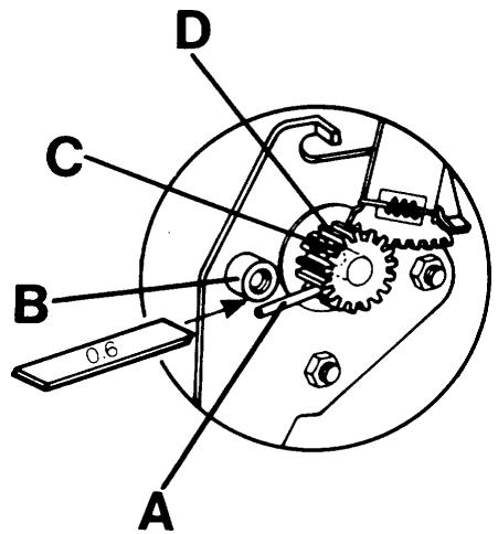
21 Pre-setting of the step motor of the guide, version 1
Get into the service mode of the machine by pressing the reverse feeding button and (-) stitch length while the main switch is turned on.
For 1100 use the service casing and press button no 9
For 1050/1090 press button no 7
Requirements
The distance between pin (A) of the cog wheel and stop lug (B) shall be 0.6 ~mm .
Adjustment
Loosen screw (C) in the cog wheel (D) and turn until requirements 0.6 ~mm is reached.
Tighten the screw and check.
Thereafter set:
The balance of the stitch length (P.36-40).
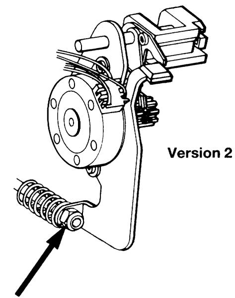
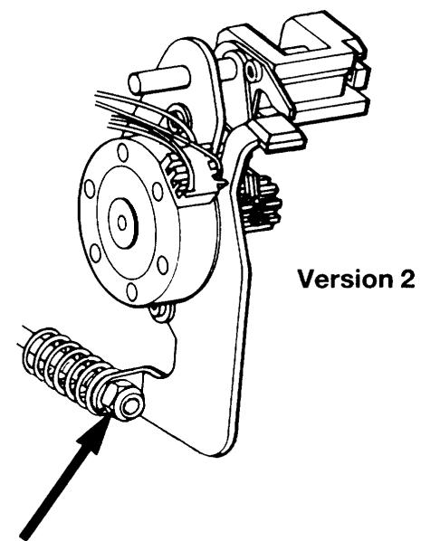
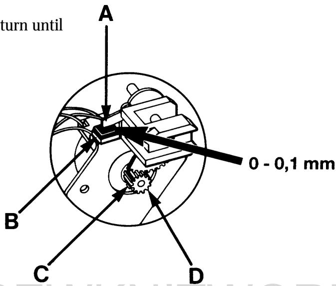
21 Pre-setting of the step motor of the guide, version 2
Get into the service mode of the machine by pressing the reverse feeding button and (-) stitch length while the main switch is turned on.
For 1200 use the service casing and press button no 9. For 1050/1070/1090 press button no 7
Requirements
The distance between pin (A) of the cog wheel and stop lug (B) shall be 0.0 - 0.1 ~mm .
Adjustment
Loosen screw (C) in the cog wheel (D) and turn until requirements 0.0 - 0.1mm is reached.
Tighten the screw and check.
Thereafter set:
The balance of the stitch length (P.36-40).
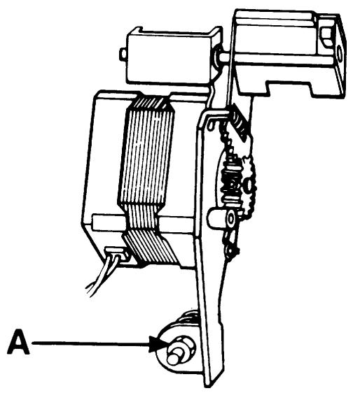
22 Pre-setting of the step motor for the side feeding
Requrities
Dismount the side feeding mechanism (page 56)
Set the handwheel so that the step motor switches between its 2 positions.
Choose a side feeding stitch from casette L.
Turn the handwheel in such a way that the step motor changes between its 2 positions.
The distance between the pin (B) and the side of the segment shall be equally large in both positions
(see fig. 1).
Adjustment
Turn on the mains switch of the machine.
Choose a side feeding stitch from casette L.
Loosen screw (A) and place the cog segment in such a way that pin (B) arrives in the middle of the opening of the cog segment (see fig. 2).
Tighten screw (A). Check according to requirements.
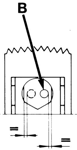
Fig.1
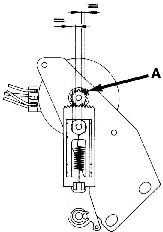
Fig. 2
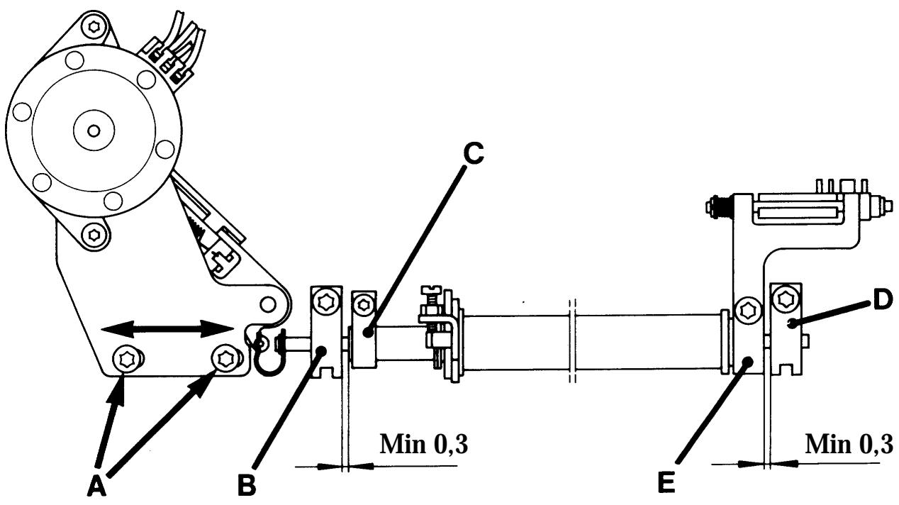
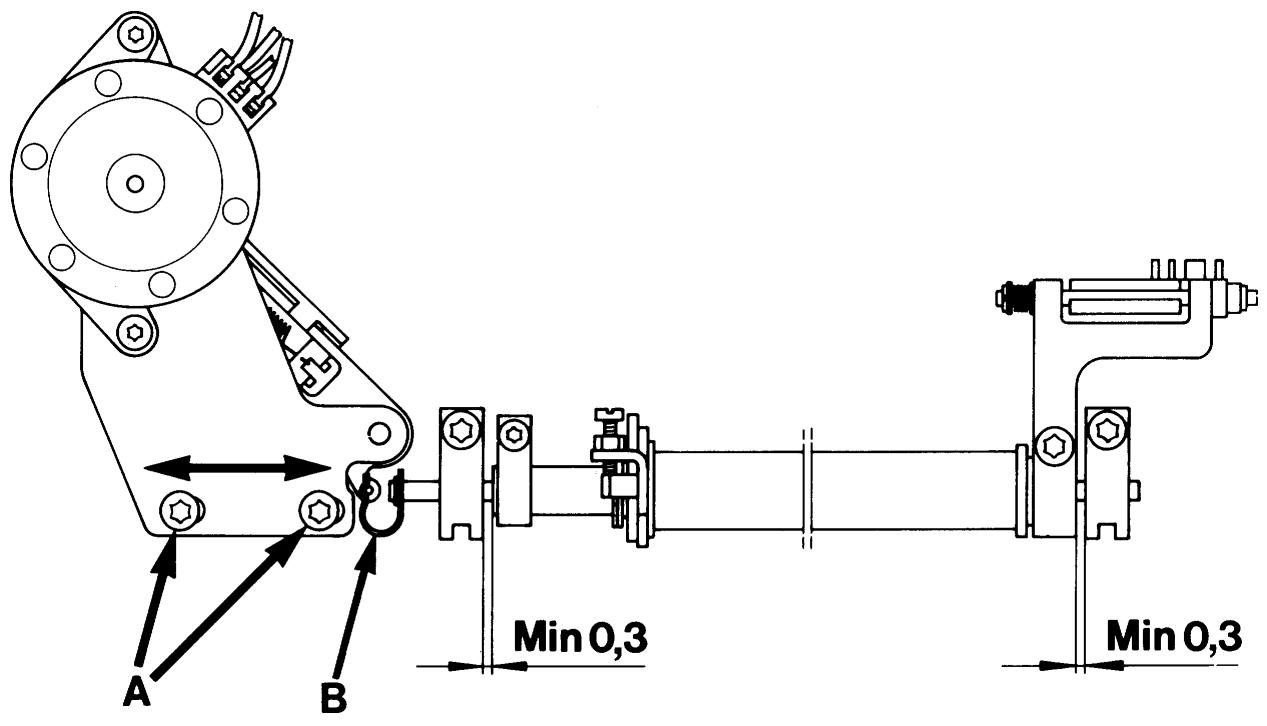
23 Setting the feeding mechanism sideways
Requirements
Set the machine on a stitch from casette L with side feeding. A play of at least 0.3mm shall be: in one side feeding position between bearing/bearing clamp (B) and link (C) of the feeding device and in the other side feeding position between bearing/bearing clamp (D) and link (E) of the feeding device.
Adjustment
Loosen screws (A) and push the step motor unit with the feeding device sideways.
Tighten the screws.
Check the play according to requirements.
NOTE!
The spherical bearings (B) and (D) must be trued so that the feeding device can move easily.
Rear cover
Dismounting
Upper cover
Undo the two screws behind the handle.
Insert a screwdriver from the side of the recess for the handle and carefully push out the upper edge.
At the same time push the cover upward.
Lower cover
Loosen the screw and push the cover to the right.

Front cover
Dismounting
Turn off the main switch.
Dismount the rear cover and the lamp guard (A).
Loosen the screw in the cable groove (B).
Loosen the four screws (C).
Press the buttons for On/Off and for the feed dip.
Push the cover carefully upward.
Remove the two cables that are connected to the circuit board.
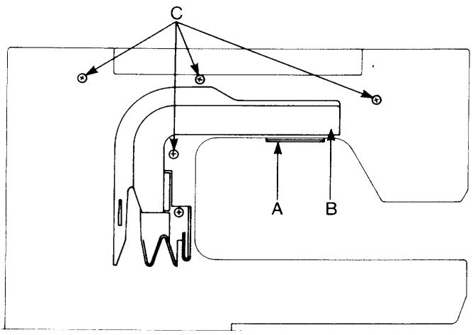
The parts of the front cover
Loosen the three cords from the LCD-board (A). Loosen the screws that hold the LCD-board and the printed circuit for the guide (B).
The LCD-board may now be removed and thereafter the guide board.
Mounting
Fit in the 3 pushbutton assemblies (C) into their guides.
Fit the printed circuit for the guide into its place.
Attach the display board under the hook on the lower edge, fit support (D) into its place.
Fit the insulating plate and tighten the screws.
Connect the cords.
MEMO-CHIP 1100/1200
The Husqvarna 1100/1200 has an exchangeable memo-chip in which the characteristics and stitches of the machine are stored.
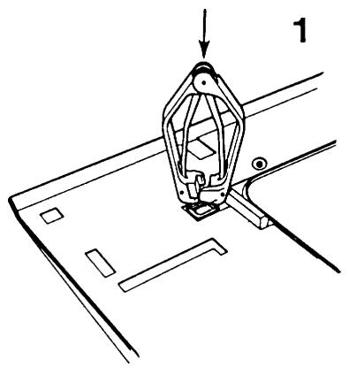
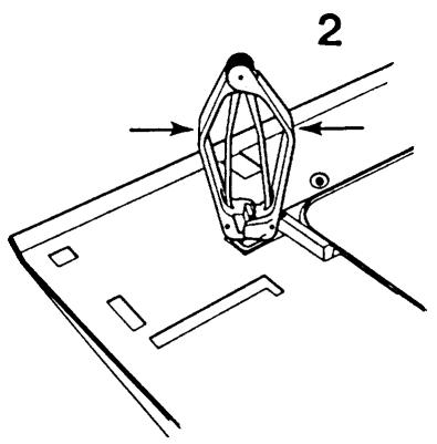
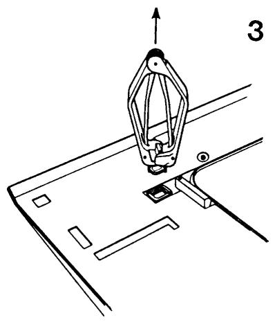
Exchange of the memo-chip
In order to be able to dismount without damaging the LCD-board a special extractor tool sshall be used.
Furthermore use a wrist band so that the components of the LCD-board are not to be damaged by static electricity (ESD).
Ref. no: Extractor tool 412 27 98-01
Wrist band 412 23 02-01
Pull out the mains cable.
Connect the wrist band to the presser bar of the sewing machine.
Dismount rear cover: (P.44).
Dismount front cover: (P.44).
Insert the extractor tool into the socket so that its plastic part comes to rest against the surface of the socket. (See ill.1).
Cautiously press the pliers together. (See ill. 2).
Check that the pliers lift the chip straight out of the socket. (See ill.3). Put the memo-chip into the ESD-package.
Put the new memo-chip into the socket.
Check that its bevel is correctly positioned (See ill.4).
Push the memo-chip into the socket.
Mount rear cover and front cover.
NOTE!
After the exchange of the memo-chip it might be necessary to "clear" it. Use the service cassette and enter the service programme of the machine by holding down the buttons for backwards feeding and minus stitch length while turning on the mains switch. First press button 29 and then button 30.
The machine is now "cleared".
Also check the stitch length balance.
Exchange of the foil keyboard 1100/1200
Dismount rear cover, front cover, LCD-board and guide board (P.44).
Dismount code spring (A).
Dismount foil keyboard (C). Remove glue residues from the surface. Remount in reverse order.
NOTE!
When mounting code spring (A) an interlayer (B) is to be used between the code spring and the foil keyboard in order to avoid to damage the contact surfaces
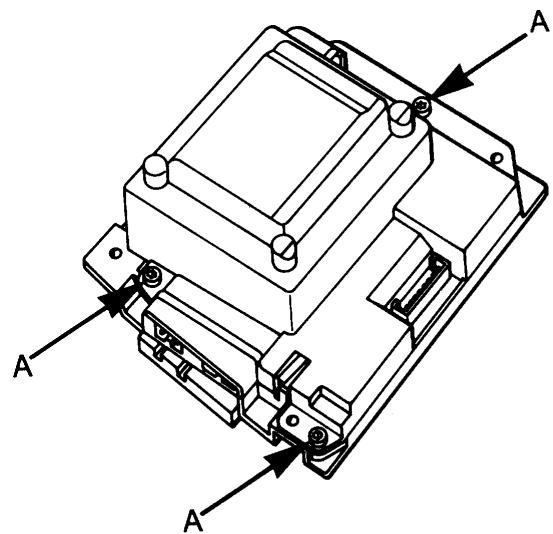
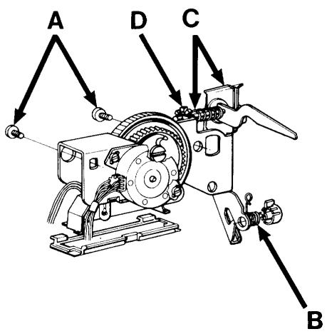
The transformer
Remove the 4 screws holding the transformer. Loosen the cord from the transformer.
Exchanging the circuit board of the transformer
- Put on the wrist band and connect it to the presser bar of the sewing machine.
- Unscrew the three screws (A) holding together the upper part and the lower part of the transformer.
- Use the tin solder from the 7 connections of the transformer to the circuit board by means of a soldering pencil and tin exhauster.
- Remove the circuit board.
- Solder the circuit board into the transformer.
- Remount the upper part and lower part of the transformer.
- Try the transformer by means of the transformer tester (which is part of the diagnoser set 412 02 56-01).
- Try the transformer in a sewing machine.
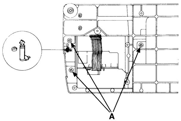
Main motor
Loosen the motor cable from the circuit board.
Loosen the screws (A) which secure the attachment for motor to the base plate.
NOTE!
The cables are connected according to the wiring diagram (P.13). The motor can be checked without being mounted into the machine. Belt tension (P.12).
Bobbin-stop
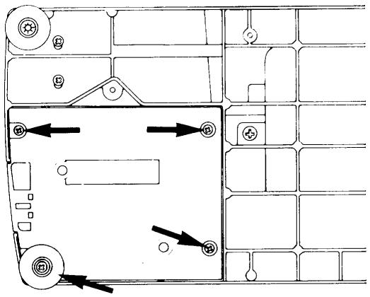
Remove the transformer (P.47).
Remove the 3 screws (A) which secure the base plate to the arm. Thereafter the bobbin-stop can be pushed downward. Setting (P.35).
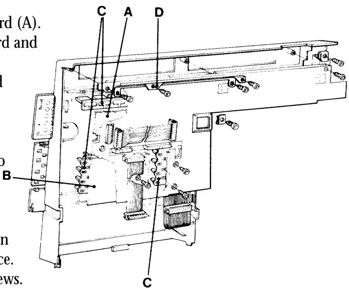
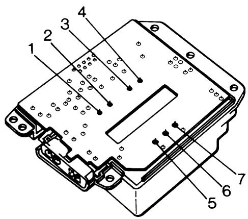
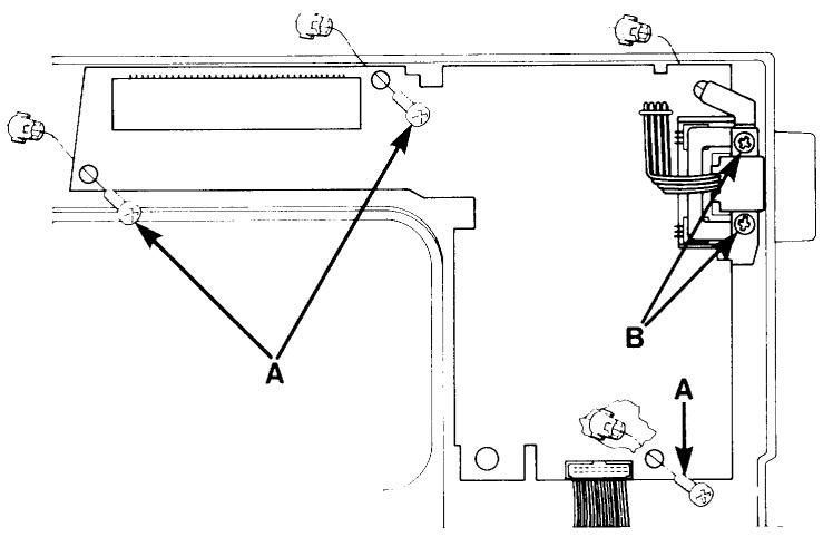
Circuit board 1100/1200
Dismounting
Remove the rear cover (P.44).
Remove the front cover (P.44).
Loosen all cables rearwisen from the circuit board.
Loosen screw (A) at the lower edge, the screw (B) holding the plate for the transistors and the screw (C) holding the arm shaft transmitter.
Loosen the cable (D) for the transformer from the board.
Wiring instruction (P.13).
Circuit board 1050/1070/1090
Dismounting
Remove the rear cover (P. 44).
Remove the front cover (P. 44).
Loosen all cables rearwisen from the circuit board. Loosen screws (A) and the screws (B) holding the plate of the arm shaft transmitter. Loosen the cable (D) for the transformer from the board. Wiring instruction (P. 13).
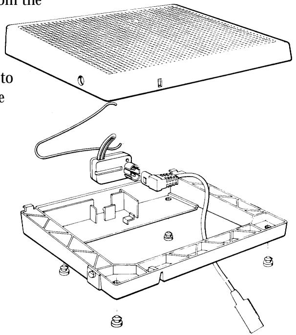
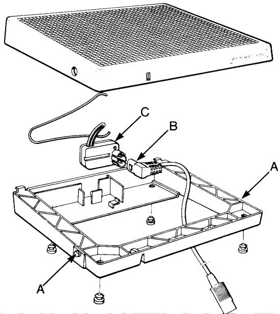
The foot control
Dismounting
Turn it upside down.
Insert a screwdriver between the sections and carefully bend the pins (A) out of their positions.
Part the sections.
Push the plug (B) of the cord device out of the potentiometer (C).
The potentiometer can now be dismounted.
Carefully bend aside the two pegs (D) holding the cord device in place and push the cord device out of the foot control.
Mount in the reverse order.
The foot control
Dismounting
Turn it upside down.
Insert a screwdriver between the sections and carefully bend the pins (A) out of their positions.
Part the sections.
Push the plug (B) device out of the potentiometer (C).
The potentiometer can now be dismounted.
Mount in the reverse order.
SEWKNITWORLD
Feeding guide compl. (step motor)
Dismounting
Turn off the main switch.
Remove the rear cover.
Remove the screws for the cable groove.
Remove the cable of the step motor from the circuit board.
Note the position of the nut (A) on the screw and remove it.
Remove the screws (B).
The feeding guide can now be removed.
Mounting
Fit the block (C) into the guide (D) (see illustration).
Push aside the stitch regulator fork (E).
Mount the feeding guide into the machine and thread the stud of the fork into the hole of the block.
Tighten the screws (B).
Tighten the nuts (A).
Connect the cables to the circuit board.
Mount the cable groove.
Thereafter set:
The stitch length balance (P.36-40).
The connecting rod
Dismounting
Remove the cable groove and all cables from the circuit board.
Loosen the spring (A) on the lower part of the connecting rod.
Lift up the connecting rod and remove it.
Mounting is done in the reverse order.
Check that the stud (B) is hooked in correctly into the feeding mechanism.
NOTE!
Connecting the cables, see the wiring diagram (P.13).
Feeding mechanism unit with stitch regulator fork
Dismounting
Remove the cable groove and all the cables from the circuit board.
Dismount the feeding guide with the step motor (P.50).
Dismount the main motor and the stitch plate.
Dismount the clips of the side motion, for 1200 (P.43).
Dismount the connecting rod (P.51).
Hook off the spring (A).
Loosen the screws (B) for the rear and front bearing clamps.
Remove the feeding mechanism compl. and the stitch regulator fork.
Mounting
Insert the feeding mechanism in such a way that the two bearings (C) come into their place and that the link at the front edge is placed under the lifting clamp (D) of the feed dog. Tighten the screws (B).
Thread the spring (E) onto its studs between the the stitch regulator fork and the arm.
Mount the feeding guide compl.
Fit the dolly (F) onto the stitch regulator fork and hook on the spring (A).
Mount the clips of the side motion, for 1200.
Mount the connecting rod.
Mount the main motor.
NOTE!
Connecting the cables, see the wiring diagram (P.13).
Therafter set:
The setting of the feed dog sideways (P.34). The feed dog height (P.34).
The lengthwise movement of the feed dog (P.35). (the stitch regulator fork has to be parallel with the rod)
The stitch length balance (P.36-40).
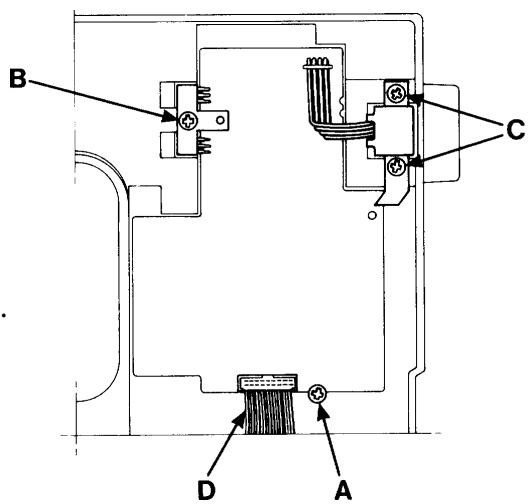
Thread tension device compl.
Dismounting
Remove the rear cover (P.44).
Remove the front cover (P.44).
Loosen the cables of the step motor and of the lamp from the the circuit board.
Loosen the two screws (A) holding the thread tension device.
The thread take-up spring (B) can be exchanged if the wedge is pushed out of the adjustment
casing and if the latter is removed from the plate.
Thread tension discs with spring (C) can be replaced by unscrewing the adjustment screw (D) of the plate.
Mount in the reverse order.
NOTE!
Connecting the cables, see wiring diagram (P.13).
The driver
Dismounting
Remove the bobbin case.
Loosen the 4 screws of the hook cover and remove the hook. Set the slot of the driver under the feed dog.
Undo the locking screw (A) of the driver which is accessible through the base plate.
Push out the driver by pressing on the shaft (B) from the rear.
Mount in the reverse order.
NOTE!
The position of the groove of the shaft.
Thereafter set:
The cog play of the hook gear (P.23).
The gap between the hook cover and the driver (P.24).
The gap between the hook and the needle (P.28).
Setting the stitch plate in relation to the needle (P.29)
Setting the timing of the hook in relation to the needle (P.30).
The lower shaft
Dismounting
Dismount transformer and motor.
Dismount the side feeding mechanism, applicable to 1200 (P.56).
Dismount the feeding mechanism compl. with the stitch regulator fork (P.51).
Remover the belt stretcher for the long cog belt.
Loosen screws (A) for the bearing clamp of the lower shaft.
Remove the dust shield (B). Thereafter the lower shaft can be removed.
Mount in the reverse order.
Adjust the axial play of the lower shaft by means of stop ring (C).
The must not exceed 0.05mm
Therafter set:
The cog play of the hook gear (P.23).
The gap between the hook cover and the driver (P.24).
The gap between the hook and the needle (P.28).
The setting of the stitch plate in relation to the needle (P.29).
The timing of the hook in relation to the needle (P.30).
The feed dog height (P.34).
The lengthwise movement of the feed dog (P.35).
The stitch length balance (P.36-40).
Position of the side motion, applicable for 1200 (P.43).
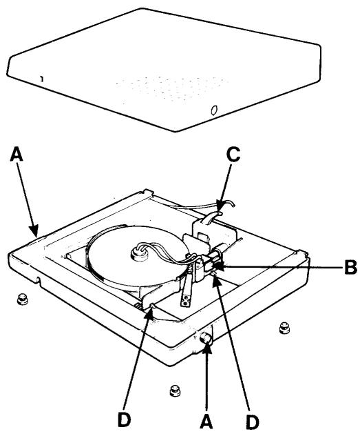
The sewing head
Dismounting
Remove the needle and the presser foot.
Set the thread take-up lever at its lower turning position.
Dismount the rear cover (P.44).
Remove the cords to the step motor, the lamp holder and the sensor for the presser foot lever from the circuit board.
Dismount the lamp holder.
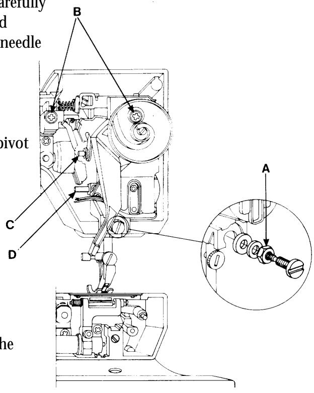
Turn the pulley in order to reach the screw at the rear.
Loosen the nut (A) and the 2 screws (B).
Pull the upper part of the sewing head outward carefully and release it first from the pivot (C) of the thread take-up lever and then from the pivot (D) of the needle bar.
Use the handwheel.
Mounting
First insert pivot (D) of the needle bar and then pivot (C) into their bearings.
Put the sewing head in position.
Use the handwheel.
Tighten the screws (B) and the nut (A).
Mount the lamp holder.
Connect the cords to the circuit board.
Wiring diagram (P.13).
Thereafter set:
The setting of the presser foot at right angles to the feeding direction (P.25).
The gap between the hook and the needle (P.28).
The setting of the stitch plate in relation to the needle (P.29).
The height of the needle (P.31).
Arm shaft
Dismounting
Dismount: rear cover (P.44).
sewing head (P.54).
connecting rod (P.51).
and tilt the stitch regulator fork (B)
outward (P.51).
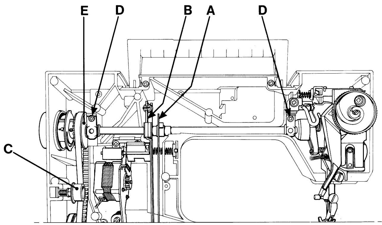
Remove the belt tensioner (C).
Remove the handwheel.
Loosen the screws for the bearing clamps (D).
Remove the arm shaft. Note! Do not damage the arm shaft transmitter.
Mount in the reverse order.
NOTE!
The axial play of the arm shaft is adjusted by means of belt wheel (E).
The play must not exceed 0.005mm
Thereafter set:
The setting of the presser foot at right angles to the feeding direction (P.25).
The gap between the hook and the needle (P.28).
The setting of the stitch plate in relation to the needle (P.29).
The timing of the hook in relation to the needle (P.30).
Dismounting the side feeding mechanism
Dismount cover, upper arm and cover, free-arm and main motor.
Loosen the clip (B) between the feeding device and the side feeding mechanism by pushing it downwards.
Loosen screws (A) and remove the side feeding mechanism.
The step motor is connected to the circuit board according to the wiring plan.
Mount in the reverse order.
Thereafter set:
- The pre-setting of the step motor of the side feeding (P.42).
- The sideways setting of the feed dog (P.34).
- The stitch length balance (P.40).
Fault-finding diagram
A. The keys of the cassette do not function.
-
Check that none of the keys of the machine stayspressed. (applies to all keys of the front panel)
-
Check that there is no bad contact in the connection from the foil keyboard of the front cover (and in other cable connections).
-
Try a new front cover, compl. with foil keyboard or just foil keyboard (P.46).
- Try a new guideboard (P.44).
- Try a new LCD- board (P.44).
B. The keys of the cassette give a seam from another cassette.
- Check by means of the service cassette that the machine reads the correct cassette.
- Check that the keying on the left of the cassette is correct. Compare with another cassette.
- If not. Check that the code spring of the cassette is freed from or is pressing sufficiently against its contact points on the foil keyboard. If not exchange code spring (P.46).
- Try a new front cover, compl. with foil keyboard or just foil keyboard (P.46).
C. All or some of the keys below the panel do not function.
- Check that none of the keys of the machine stays pressed.
- Try a new LCD-board (P.44).
D. All or some of the keys of the sewing advisor do not function.
- Check that none of the keys of the machine stays pressed.
- Check the connection to the guideboard.
- Try a new guide-board (P.44).
E. All or some of the keys of the upper foil keyboard do not function. 1050/1070/1090
- Check the cable connection of the foil keyboard to the circuit board.
- Try a new foil keyboard.
- Try a new circuit board (P.48).
F. All or some of the keys of the lower foil keyboard do not function. 1050/1070/1090
- Check the cable connection of the foil keyboard to the circuit board.
- Try a new foil keyboard.
- Try a new circuit board (P.48).
G. None of the keys of the machine functions.
- Check that none of the keys of the machine stays pressed.
- Replace the memo-chip (P.45).
- Try a new LCD-board (P.44).
H. The machine only runs at reduced speed.
- Check that the button for the twin needle is not pressed.
- Check the function of the speed button.
- Try a new LCD-board.
- If this occurs during service, check that the motor does not run in reverse.
I. The machine is completely dead. Motors, displays and diodes do not function.
- Check the main cable.
- Check that the spring to the main switch is not pushing in the switch on the transformer while the main switch is on.
- Check the transformer with the diagnoster and replace it or the circuit board in case of incorrect reading (P.47).
- Try a new circuit board (P.48).
J. The machine does not work when the foot control is pressed, but the display, the lamp and the light emitting diode function.
- Check that the contact of the cord device/of the cord is correctly pushed into the potentiometer (P.49).
- Check by means of a new foot control. (potentiometer, cord device) (P.49).
- Check that the bobbin stop sensor is not pressed (P.48).
- Check that the presser foot display does not blink even if the presser foot is down. Exchange the micro switch of the sewing head (P.18).
- Try a new motor (P.48).
- Try a new circuit board (P.48).
K. The machine races when switched on or by pressing the foot control.
- Try a new circuit board (P.48)..
-
Try a new LCD-board (P.44).
L. The zig-zag movement of the machine does not work correctly. -
Check that the symbol for twin needle does not blink on the display.
- Check by means of the service cassette that the arm shaft sensor is working. In case of error, replace circuit board (P.48).
- Check that the cable connection of the step motor to the circuit board is correct (P.26).
- Check the signals of the circuit board to the step motor by means of the diagnoster and replace the circuit board in case of error (P.48).
- Replace sewing head, compl. or step motor (P.54).
M. The feeding movement of the machine does not work correctly.
- Check by means of the service cassette that the arm shaft sensor is working. In case of error, replace the circuit board (P.48).
- Check the pre-setting of the step motor of the guide by means of the service cassette (P.41).
- Check that the cable connection of the step motor to the circuit board is correct.
- Check the signals of the circuit board to the step motor by means the diagnoster and replace the circuit board in case of error (P.48).
- Replace feeding guide, compl. or step motor (P.50).
N. The stitch length balance of the machine is not correct. (buttonholes, pattern stitches, letters)
Always use correct presser foot.
- Check the pre-setting of the step motor of the guide by means of the service cassette (P.41).
- Check that there is no friction in the feeding mechanism.
- Adjust the stitch length balance (P.36-40).
O. The automatic thread tension does not work.
- Check by means of the service cassette the step motor of thread tension.
- Check the cable connections between step motor and circuit board.
- Try a new thread tension device, compl. or step motor (P.52).
- Try a new circuit board (P.48).
- Try a new LCD-board (P.44).
P. One or both LCD-displays are not working at all or only partly.
- Check that there is a correct contact between the memo-chip and its socket on the LCD-board.
- Check the cable connections between LCD-board and circuit board.
- Try a new memo-chip (P.45).
- Try a new LCD-board (P.44).
- Try a new circuit board (P.44).
Q. One or all of the diodes of the sewing advisor do not work.
- Check the connection between the guideboard and the LCD-board.
- Try a new guideboard (P.48).
R. The machine does not alarm when the lower thread ends.
CHECK: Insert the bobbin case without bobbin and let the machine run about 10 revs. It should now alarm. Insert a full bobbin into the bobbin case and let it run about 10 revs. The alarm should disappear now. If not.
- Clean both diodes of the lower thread sensor and the mirror of the bobbin case and remove fluff. Try again.
- Check the cable to the lower thread sensor.
- Replace lower thread sensor,compl.
- Try a new circuit board (P.48).
- Try a new LCD-board (P.44).
S. The machine is sewing with the presser foot lifted.
- Check the cable to the micro switch of the presser foot lever.
- Check that the peg of the presser foot lever is pushing in the micro switch.
- Try a new micro switch or measure it according to the service manual (P.18).
- Check the cables between the circuit board and the LCD-board.
- Try a new circuit board (P.48).
- Try a new LCD-board (P.44).
T. The buttonhole sensor does not work.
- Make sure that the contact of the buttonhole sensor is correctly inserted and check its function according to the operating manual.
- Try a new buttonhole sensor or check it according to the service manual.
- Check the cable from the lamp glass to the circuit board or change tha lamp glass (P.18).
- Check the cable connections between the circuit board and the LCD-board.
- Try a new circuit board (P.48).
- Try a new LCD-board (P.44).
U. The machine always chooses buttonhole measuring when sewing buttonholes.
The presser foot and its information flash at normal sewing on the left display.
- Check that the cable connection (to the buttonhole sensor) between the lamp glass and the circuit board are correct. Replace the lamp glass if necessary.
V. The side motion of the machine does not work at all.
- Check the pre-setting of the step motor of the side motion (P.42).
- Check the sideways setting of the feeding mechanism (P.43).
- Check the smooth running of the feed dog in the stitch plate (P.34).
- Check that the cable connection between the step motor and the circuit board is correct.
- Try a new side feeding mechanism (P.56).
X. Marks full speed on the display at side motion stitches.
- If only the side motion function is influenced, replace the memo-chip (P.45).
- If the speed can't be regulated, replace the circuit board.
- If the speed can change, replace the memo-chip.
Y. The machine sews straight stitching only backwards.
- If there are not any further problems, replace the memo-chip (P.45).
Z. All symbols flash on the display.
- Replace the memo-chip (P.45).
- Replace the LCD-board (P.44).
SEWKNITWORLD