
RMU S40 - Thermostat Nibe - Free user manual and instructions
Find the device manual for free RMU S40 Nibe in PDF.

| Product type | Connected room thermostat |
| Brand | Nibe |
| Model | RMU S40 |
| Power supply | 12 VDC, 24 VAC or 5 VDC via USB (5 V power adapter, max cable 3 m) |
| Dimensions (display panel) | 64 x 85 x 16 mm |
| Dimensions (rear panel) | 88 x 88 x 8 mm |
| Weight | 80 g |
| Protection rating | IP20 |
| Operating temperature | 5 to 55 °C |
| Ambient temperature | 5 to 50 °C |
| Connection | Wired (up to 50 m, 0.5 mm² cross-section) or wireless 2.4 GHz |
| Max number of wired units | 8 RMU S40 (up to 3 without external power supply) |
| Display | Color touchscreen |
| Room sensor | Integrated, for temperature and humidity measurement |
| Main functions | Temperature and humidity control, night mode, away mode, curve programming, zone display |
| Software update | Automatic via main product |
| Memory card slot | Micro SD |
| Maintenance and cleaning | Clean with a soft dry cloth; do not use abrasive products |
| Safety | Complies with directive 2014/53/EU; installation by a certified electrician; disconnect the main product before installation |
| Spare parts and repairability | Contact an approved installer or Nibe after-sales service |
| General information | Manufactured by Nibe; declaration of conformity available at nibe.fr |
Frequently Asked Questions - RMU S40 Nibe
User questions about RMU S40 Nibe
0 question about this device. Answer the ones you know or ask your own.
Ask a new question about this device
Download the instructions for your Thermostat in PDF format for free! Find your manual RMU S40 - Nibe and take your electronic device back in hand. On this page are published all the documents necessary for the use of your device. RMU S40 by Nibe.
USER MANUAL RMU S40 Nibe

natural_image
Blue line icon of a wrench inside a hexagon (no text or symbols)IHB 2220-2
631705
Table of Contents
Svenska
Suomeksi
4Viktig information 45Tärkeää
5Allmänt 46Yleistä
6Rumsenhetens konstruktion 47Huoneyksi
7Elinkoppling 48Sähköaser
9lgångkörning ____ 50Käyttööno
10Styrning - Introduktion 510hjaus -
19Room unit design 61Raccorder
20Electrical connection 63Mise en s
22Commissioning 64Command
Create proles in the main product's menu 4.3 - Proles ____
KOMPATIBLA PRODUKTER
natural_image
Diagram of a wall-mounted electrical switch panel with labeled components (no text or symbols present)natural_image
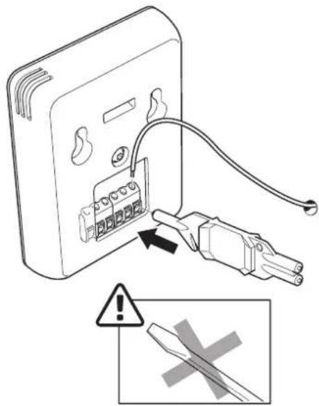
Diagram showing two electrical outlets connected by a cable with a plug, accompanied by a warning symbol (no text or labels present)natural_image
Diagram showing a device being inserted into a panel, with arrows indicating cable insertion (no text or symbols present)natural_image
Illustration of a device with a screen and directional arrow, no text or symbols presentRumsenhetens konstruktion
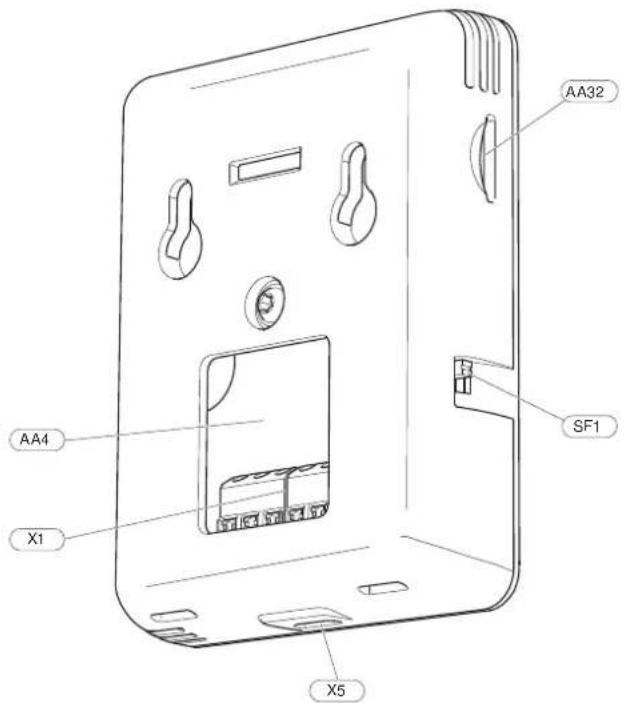
DisplayenhetAA4
INKOPPLING MOT HUVUDPRODUKT
PLATS FÖR MINNESKORT
This manual describes installation and service procedures for implementation by specialists.
The manual must be left with the customer.
This appliance can be used by children aged from 8 years and above and persons with reduced physical, sensory or mental capabilities or lack of experience and knowledge if they have been given supervision or instruction concerning use of the appliance in a safe way and understand the hazards involved. Children shall not play with the appliance. Cleaning an user maintenance shall not be made by children without supervision.
This is an original manual. It may not be translated without the approval of NIBE Rights to make any design or technical modifications are reserved.
©NIBE 2022.
MARKING
Explanation of symbols that may be present on the product's label(s).

Read the Installer Manual.

Class III control symbol.
RECOVERY
Leave the disposal of the packaging to the installer who installed the product or to special waste stations.
Do not dispose of used products with normal
household waste. It must be disposed of at a special waste station or dealer who provides this type of service.
Improper disposal of the product by the user results in administrative penalties in accordance with current legislation.
OPEN SOURCE CODE
be This product contains software covered by an open source code licence. For more information as well as access to the source code, visit opensource.nibe.eu.
SYMBOLS
Explanation of symbols that may be present in this manual.

NOTE
This symbol indicates danger to person or machine.

Caution
This symbol indicates important information about what you should consider when installing or servicing the installation.

TIP
This symbol indicates tips on how to facilitate using the product.
GENERAL
NIBE hereby declares that this type of radio equipment EA001-A-XXX corresponds with directive 2014/53/EU. The full text of the EU Declaration of Conformity can be found at nibe.eu.
General
With RMU S40 you can control and monitor your NIBE h pump/indoor module/control module (main product) from another room in the house.
COMPATIBLE PRODUCTS
Main products in NIBE S-series.*
*RMU S40 is not compatible with SMO S30.
CONTENTS
1 x RMU S40 with rear panel
MOUNTING
RMU S40 can be installed directly against a wall or with the heat aid of the enclosed rear panel. If you use the enclosed rear panel, you can install RMU S40 in a standard connection box.
If you want to use the room sensor in RMU S40, the position of the unit is important, see section Room sensor.
Use all mounting points and mount the module upright, at against the wall. Leave at least 100 mm of free space around the module to allow access and make cable routing easier during installation and servicing.

Caution
The screw type must be adapted to the surface on which installation is taking place.
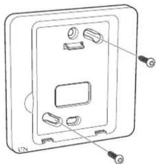
INSTALLATION WITHOUT REAR PANEL
- Unscrew 2 screws at a distance of 32 mm.
- Connect RMU S40 to the main product, see section "Electrical connection".
- Hang RMU S40 on the screws.
INSTALLATION WITH REAR PANEL
- Screw the rear panel onto the wall using 2 screws.
natural_image
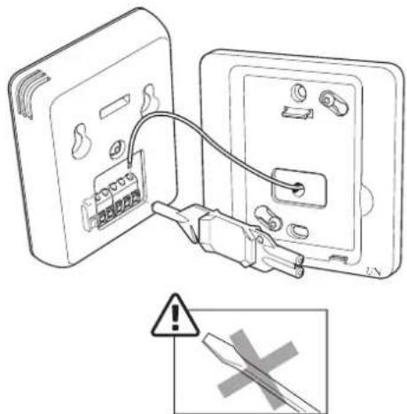
Technical line drawing of a wall-mounted electrical outlet with mounting holes and connectors (no text or symbols)- Connect RMU S40 to the main product, see section "Electrical connection".
natural_image
Diagram showing two electrical outlets connected by a cable with a fuse, accompanied by a warning symbol (no text or labels present)Room unit design
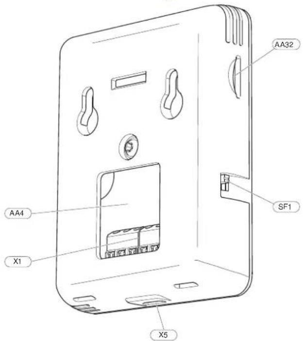
Display unitAA4
Space for memory card (Micro-SD)AA32
Terminal block, communication and voltageX1
Power supply, Micro-USBX5
On/O button (Switch)SF1
Designations according to standard EN 81346-2.
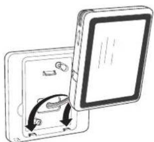
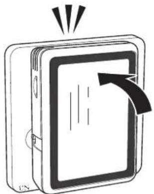
- Angle the display unit and secure the unit to the two clamps at the bottom of the rear panel.
natural_image
Diagram showing a device being inserted into a flat panel, with arrows indicating the process (no text or symbols present)- Press RMU S40 rmly to the top of the rear panel.
natural_image
Diagram of a device with an arrow indicating rotation or movement, no text or symbols presentElectrical connection

NOTE
All electrical connections must be carried out an authorised electrician.
Electrical installation and wiring must be carried out in accordance with national provisions.
The main product must be disconnected from power supply when installing RMU S40.
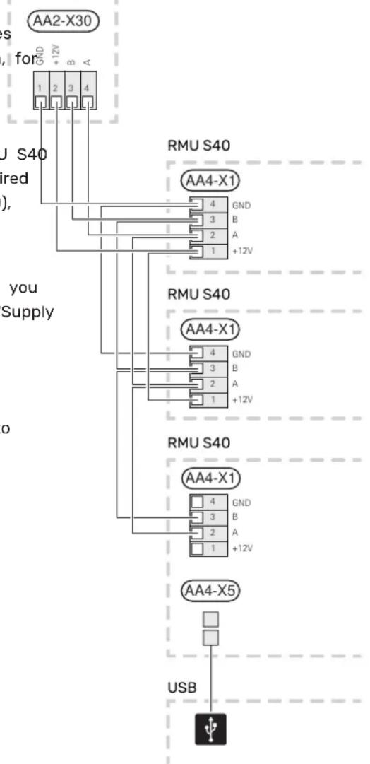
CONNECTION TO MAIN PRODUCT
Heat pump/indoor module
The terminal block in RMU S40 (AA4-X1) is connected to terminal block X30:1-4 on the PCB (AA2) in the heat pump/indoor module.
If several accessories are to be connected, or are already installed, the boards are connected in series.
theBecause there can be different connections for accessories, you should always read the instructions in the manual for the accessory that is to be installed.
- To prevent interference, sensor cables to external connections must not be laid close to high voltage cables.
- The minimum area of communication and sensor cables to external connections must be 0.5 mm ^2 up to 50 m, for example EKKX, LiYY or equivalent.
- RMU S40 restarts after a power failure.
You can connect max 32 wireless units and 8 wired RMU S40 to the main product. If you connect more than three wired units to the main product (of which max. two RMU S40), these require an external power supply.
C- Heat pump, indoor module
AA2-X30

POWER SUPPLY
RMU S40 is not battery powered. For the power supply, you can use a USB mains adapter (5 V) and connect it to "Supply voltage, Micro-USB" (X5).
Max. cable length for USB connection: 3 metres.
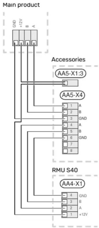
WIRED CONNECTION
You can connect your RMU S40 to your main product to provide power and communication.
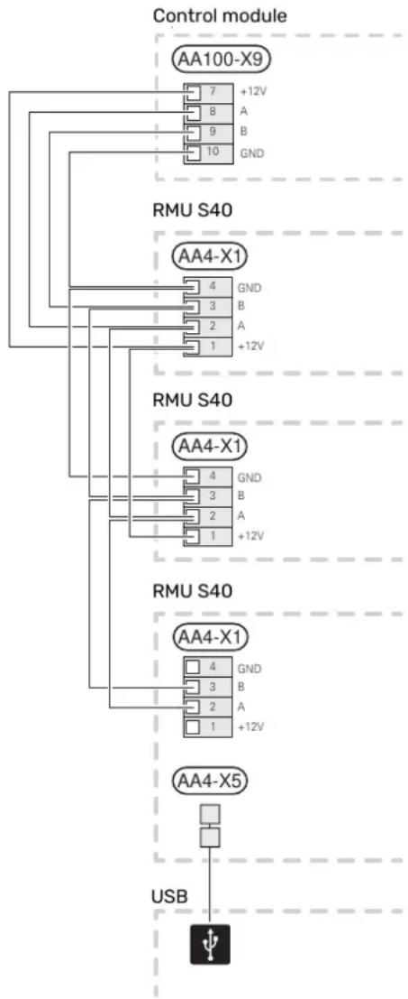
Control module
CONNECTION OF ACCESSORIES AND AN
The terminal block in RMU S40 (AA4-X1) is connected to RMU S40
terminal block X9:7-10 on the joint board (AA100) in the If several accessories are to be connected, or are already control module. installed, the boards are connected in series.
If several accessories are to be connected, or are already because there can be different connections for accessories, installed, the boards are connected in series. you should always read the instructions in the manual for
Because there can be different connections for accessories, the accessory that is to be installed.
you should always read the instructions in the manual for connect a +12V supply cable from the main product to your accessory that is to be installed. RMU S40. RMU S40 should be connected last in the commu-
flowchart
graph TD
    A["Control module"] --> B["AA100-X9"]
    B --> C["7 +12V"]
    B --> D["8 A"]
    B --> E["9 B"]
    B --> F["10 GND"]
    G["RMU S40"] --> H["AA4-X1"]
    H --> I["4 GND"]
    H --> J["3 B"]
    H --> K["2 A"]
    H --> L["1 +12V"]
    M["RMU S40"] --> N["AA4-X1"]
    N --> O["4 GND"]
    N --> P["3 B"]
    N --> Q["2 A"]
    N --> R["1 +12V"]
    S["RMU S40"] --> T["AA4-X1"]
    T --> U["4 GND"]
    T --> V["3 B"]
    T --> W["2 A"]
    T --> X["1 +12V"]
    Y["USB"] --> Z["4 GND"]
    Y --> AA["3 B"]
    Y --> AB["2 A"]
    Y --> AC["1 +12V"]

Caution
Always install a +12V supply cable from the main product to the accessory with the AXC module, for connection to RMU S40.
Commissioning
ROOM SENSOR
The room unit RMU S40 contains a room sensor with the for example when both underoor heating and radiators are same function as the room sensor (BT50) accompanying tted in a property.
the main product.
This makes it possible to select which room sensor the product will use for displaying and control of the room temperature, where applicable.
A climate system can be divided up into several zones, which can be allocated one or more sensors or other accessories. A zone could be a specific room or part of larger premises.

Caution
In the main product's menu 1.3.3 - "Room units", you can choose the room sensor that you want to use for inspection control.
The room unit has up to four functions:
- Show current room temperature in the heat pump/indoor module display.
- Provides the option of changing the room temperature.
-
Provides the option of changing/stabilising the room temperature.
-
Provides the option of presenting and controlling the humidity.
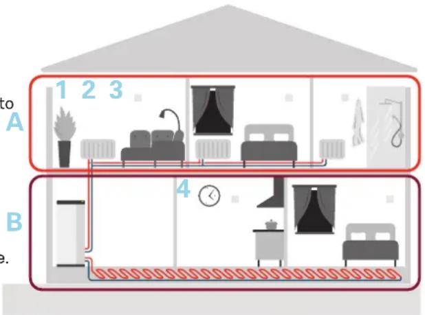
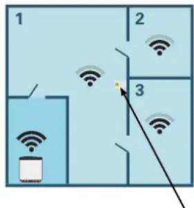
The example shows a property with two climate systems.
Climate system "A" is a radiator system with three zones.
With a controlled radiator valve, the temperature can be controlled individually for zones 1, 2 and 3. Inner
Climate system "B" is an underoor heating system with one zone, which is the controlling zone.
Install the room unit in a neutral position where the set temperature is required. A suitable location is on a free wall in a hall approx. 1.5 m above the oor. It is important that the room unit is not obstructed from measuring the
correct room temperature, for example by being located a recess, between shelves, behind a curtain, above or to a heat source, in a draught from an external door or direct sunlight.
Control of the room unit is activated in menu 1.3.3 - "R units".

Caution
Closed floor/radiator thermostats affect the indoor temperature.
SETTINGS IN THE MAIN PRODUCT
Adjust the basic settings for each RMU S40 in the main Main product. In order to determine more easily the room in which RMU S40 is located, you can give each room unit a unique name.
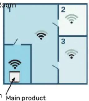
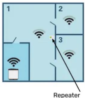
REPEATER RPP 10
In the communication is weak between the main product and an accessory in a zone, a repeater (RPP 10) may need to be installed to amplify the signal between the zones.

Caution
The main product's software must be the latest version.
WIRELESS CONNECTION
Control - Introduction
- Go to the main product and select menu 5.4 - "Connect wireless units" and follow the guide. Here, you give e
RMU S40 a unique name.

TIP
Go to menu 2 - "Connections" to nd the start guide again at a later date.
- Select wireless connection in your RMU S40.
- Wait for the message "Connection succeeded".
- Make your settings for RMU S40 in the main product's menu 1.3.3 - "Room units".

Caution
See the Installer Manual for the main product.
WIRED CONNECTION
In order to give RMU S40 a unique name in the main product, On/Off button
it must rst be allocated an address, a number (1 - 8):
- Select an address for RMU S40 by allocating it a unique number (1 - 8) in menu 2 - "Connections".
- Go to the main product and select menu 7.2.1 - "Add/remove accessories" and activate RMU S40 or press "Search for accessories".
- Select wired connection in your RMU S40.
- Select an address (1 - 8) for your RMU S40.
In the event of a communication fault between RMU and your main product, you are asked to check the lected address and adjust if necessary.
- Make your settings for RMU S40 in the main product's menu 1.3.3 - "Room units".

Caution
See the Installer Manual for the main product.
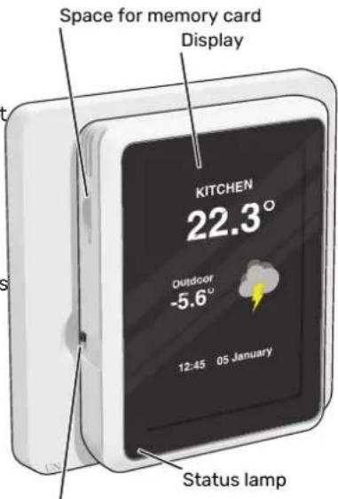
THE STATUS LAMP
the status lamp indicates current operating status. It:
• is not lit during normal operation.
- lights red in the event of a deployed alarm.
If the status lamp is red, you receive information and suggestions for suitable actions on the display.
THE ON/OFF BUTTON
540 on/o button (SF1) has two functions:
sestart
- switch o
To start: Move the switch up.
To turn o: Move the switch down.
THE DISPLAY
Instructions, settings and operational information are shown on the display.
SPACE FOR MEMORY CARD
On the left side of the room unit, there is space for a memory card (Micro-SD)

TIP
RMU S40 is updated automatically from the main product when new software is available.
NAVIGATION
RMU S40 has a touchscreen where you simply navigate pressing and dragging with your nger.
SELECT
Most options and functions are activated by lightly pressing on the display with your nger.
HOME SCREENS
by INFORMATION PAGES
Which information is displayed depends on which product you have and which accessories are connected to the product.
BROWSE
The dots at the bottom edge show that there are more pages.
Drag to the right or left with your nger to browse between the pages.
SCROLL
If the menu has several sub-menus, you can see more information by dragging up or down with your nger.
You can always press "X" to return to the home screens.
FUNCTION PAGES
On the function pages, you can both view information about the current status and easily make the most common settings. The function pages that you see depend on the product you have and the accessories that are connected to the product.
CHANGE A SETTING
Press the setting you want to change.
If it is an on/o setting, it changes as soon as you press it.
If there are several possible values, a spinning-wheel appears that you drag up or down to nd the desired value.
Drag to the right or left with your nger to browse between the function pages.
Press to save your change, or press to cancel.
HELP MENU
In some menus, there is a symbol indicating that extra help is available.
Press the symbol to open the help text.
You may need to drag with your nger to see all text.
Press the card to adjust the desired value. On certain function pages, drag your finger up or down to obtain more cards.
MENU TREE
In the menu tree, you can nd all menus and can make more advanced settings.
Create proles in the main product's menu 4.3 - Proles
In the main product's menu 4.3, you have the option to create proles and select the zones and functions to which proles will have access. A prole might, for example, be apartment with its own accessories.
You must have created the zones previously. You can nd more information about climate systems and zones in the main product's Installer Manual.
- Create and name a prole (up to eight proles).
- Select one or more zones. In order for your RMU S40 be connected to the prole, it must be located in one of the zones you select.
- Add the functions to which the profile is to have acc
Examples of functions:
- alarm
- home/away
- cooling
- pool
- PV solar
- hot water
- ventilation
- heating
On the RMU S40 display, the prole to which it belongs then shown.

Caution
A RMU S40 connected to a prole will be locked, and will only show information related to the selected prole.
Control - Menus
HOME SCREENS

Caution
The menus and control options that are available can be controlled by proles, see section "Create proles in the main product's menu 4.3 - Proles".
HEATING AND COOLING
You make temperature settings for your installation here.
If the climate system in the house has several zones for heating or cooling, this is shown on the display by a function page for each zone.
Setting the temperature(without controlling room sensor activated):
Setting range: -10 - 10
The display shows the set value for heating/cooling (curve oset). To increase or reduce the indoor temperature, increase or reduce the value in the display.
The number of steps the value has to be changed in order to achieve a one degree change to the indoor temperature depends on the climate system. One step is usually enough, but in some cases several steps may be required.
If multiple zones in a climate system do not have activated room sensors, these will have the same curve oset.
Setting the desired value. The new value is shown on the right-hand side of the symbol on home screen cooling.
Setting the temperature (with controlling room sensor activated):
Heating
Setting range: 5 - 30 °C
Cooling
Setting range: 5 - 35°C
The value in the display appears as a temperature in ^ C, if the zone is controlled by a room sensor.

Caution
A slow climate system, such as underfloor heating, may be unsuitable for controlling with room sensors.

Caution
An increase in the room temperature can be slowed by the thermostats for the radiators or under oor heating. Therefore, open the thermostats fully, except in those rooms where a cooler temperature is required, e.g. bedrooms.

TIP
If the room temperature is constantly too low/high, you increase/decrease the value by one step in menu 1.1.1.
If the room temperature changes when the outdoor temperature changes, you increase/decrease the curve slope by one step in menu 1.30.1.
Wait 24 hours before making a new setting, so the room temperature has time to stabilise.
MENU 1 - NIGHT MODE
NIGHT MODE
Setting: On/O
SCHEDULE NIGHT MODE
Setting: 00.00 - 23.59
You can activate night mode here.
Activate night mode during the time of day you want to switch o the backlight.
MENU 2 - CONNECTIONS
Select wireless or wired connection.
WIRELESS CONNECTION
Select wireless connection.
Go to the main product and select menu 5.4 - "Connect wireless units".
WIRED CONNECTION
Select a communication address for RMU S40 by allocating it a unique number in this menu.
: Seattierg: 1 - 8
HOT WATER
When there is a temporary increase in hot water demand,
this menu can be used to select an increase in the hot setting: 1 - 8
temperature for a selectable time.
You can also select "More hot water" in the main product's
menu 2.1.
MENU 4 - LICENCES
ct's You can nd licences for open source code here.
VENTILATION
The ventilation in the accommodation can be temporarily increased or reduced here.
MENU 5 - SENSOR CALIBRATION
Here, you can calibrate the temperature sensor's value. The 'set value is added to, or deducted from, the sensor's current measured value.
The return time for the fan may, if necessary, be changed. Setting: -5.0 - 5.0 (Default 0)
in the main product's menu 1.2.5 - "Fan return time".
ed Setting: -5.0 - 5.0 (Default 0)
POOL
Here you can change the temperature of the water in the pool or activate/deactivate heating.
MENU 7 - DISPLAY ZONES
Here, you can select the zones that you want to be displayed in your RMU S40, for heating and cooling.
You can choose to display a maximum of ten zones.
PV SOLAR
You can read off the value of the power that the solar are currently providing.
MENU 8 - FACTORY SETTING
panels
Reset to factory setting.
You can also see how much energy the solar panels have produced during the current calendar month.
MENU 9 - INFORMATION
Here, information is displayed about the product and the software version that is installed.
HOME/AWAY
Here you can activate or deactivate the "Away mode" function.
The function is activated if you select "Away" when you leave your home. In order to deactivate, select "Home". The settings for "Away mode" are made in the main product's menu 4.5 "Away mode".

Caution
You can choose to control your main product according to the relative humidity (RH) in the air, which is measured by your RMU S40. Activate choice in menu 7.1.6.4 - "Humidity control" in the main product.
You can also choose to control your main product malfunction has occurred, which is indicated according to the relative humidity (RH) in the airated by the status lamp shining with during cooling operation. (If you have cooling in- steady red light. A dialogue box appears stalled and activated.) Activate this choice in men in the display, containing information 7.1.7.2 - "Humidity control" in the main product, about the alarm.
Select "Limit RH in cold".
Disturbances in comfort
In most cases, RMU S40 notes a malfunction (a malfunction can lead to disruption in comfort) and indicates this with alarms, and instructions for action, in the display.
MANAGE ALARM
In the event of an alarm, some type malfunction has occurred, which is indicated by the status lamp shining with steady red light. A dialogue box appears in the display, containing information about the alarm.
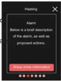
ALARM
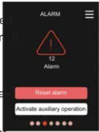
In the event of an alarm with a red status lamp, a malfunction has occurred. The display shows what type of alarm is and lets you reset the alarm.
In many cases, it is sucient to select "Reset alarm" for the installation to revert to normal operation.
If the alarm indication disappears after
you have selected "Reset alarm", the alarm has been remedied. If the alarm recurs, the cause of the problem remains.
"Auxiliary operation" is a type of emergency mode. This means that the installation attempts to produce heat and/or hot water, even though there is some kind of problem. This could mean that the heat pump's compressor is not in operation. In this case, any electric additional heat produces heat and/or hot water.

Caution
To select "Auxiliary operation", an alarm action must be selected in menu 7.1.8.1 - "Alarm actions" in the main product.

Caution
Selecting "Auxiliary operation" is not the same as correcting the problem that caused the alarm. The status lamp will therefore remain red.
TROUBLESHOOTING
COMMUNICATION ERROR
RMU S40 has lost contact with the main product.
Wireless connection
- Check that the distance between the main product and RMU S40 is not too great.
- If the communication is weak between the main product and an accessory in a zone, a repeater (RPP 10) may need to be installed to amplify the signal between the zones.
Wired connection
- Check that the cable is correctly connected between RMU S40 and the main product.
- Check that the addresses in the room unit's "Installation" menu and the main product's 7.2.1 menu correspond.
THE DISPLAY IS OFF
No information is visible on the display.
- Check that the screensaver is active by pressing the screen.
- Check that the On/O button is set to On.
- Check that the cable is correctly connected between RMU S40 and the main product.
- If RMU S40 is set to "Night mode", the display is o. (See Menu 1 - Night mode.)
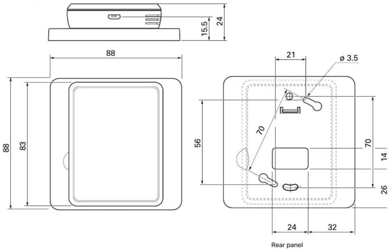
Technical data
DIMENSIONS
TECHNICAL SPECIFICATIONS
| RMU S40 | ||
| 12VDC 100mARated voltage ( | ||
| 24VAC 120mARated voltage | ||
| 5VDC 250mARated voltage ( | ||
| IP20Enclosure class | ||
| 0.33kVRated value for in | ||
| 2Pollution degree | ||
| Wireless units | ||
| 3.5dbm2.405 - 2.480 G | ||
| Miscellaneous | ||
| Type 10operation mode (E | ||
| Operating range, temperature | °C | 5 - 55 |
| %RHOperating Range 80 relative humidity | ||
| Ambient temperature | °C | 5 - 50 |
| Dimensions and weight | ||
| Rear panel (Width x Height x Depth) | mm | 88 x 88 x 8 |
| Display dimensions panel (Width x Height x Depth) | mm | 64 x 85 x 16 |
| Weight | g | 80 |
| Article data | ||
| Part No. | 067 650 | |
Deutsch
natural_image
Diagram showing two electrical outlets connected by a cable with a fuse, accompanied by a warning symbol (no text or labels present)natural_image
Diagram showing a device being inserted into a tablet, with arrows indicating the process (no text or symbols present)natural_image
Illustration of a device with an arrow pointing to a screen, emitting rays (no text or symbols)DAS DISPLAY IST AUSGESCHALTET
- Ripusta RMU S40 ruuveille.
ASENNUS TAKAKAPPALEEN KANSSA
natural_image
Technical line drawing of a wall-mounted electrical outlet with mounting holes and connectors (no text or symbols)natural_image
Diagram showing a device being inserted into a rectangular panel, with arrows indicating the process (no text or symbols present)natural_image
Illustration of a device with a screen and directional arrow, no text or symbols presentSähköasennukset

HUOM!
LÄMMITYS JA JÄÄHDYTYS
PRODUITS COMPATIBLES
natural_image
Technical line drawing of a wall-mounted electrical switch panel with mounting holes and screw placements (no text or symbols)natural_image
Diagram showing two electrical connectors connected to a cable with a warning symbol (no text or labels present)natural_image
Diagram showing a device being inserted into a flat panel, with arrows indicating the process (no text or symbols present)natural_image
Illustration of a device with a screen and directional arrow, emitting light rays (no text or symbols)Alimentation, micro-USBX5
RACCORDEMENT AU PRODUIT PRINCIPAL
COMPATIBELE PRODUCTEN
INSTALLATIE MET ACHTERPLAAT
Ontwerp ruimte-unit
natural_image
Diagram showing two electrical connectors connected to a cable with a warning symbol (no text or labels present)
BedieningseenheidAA4
Voeding, Micro-USBX5
natural_image
Diagram showing a device being inserted into a rectangular panel, with arrows indicating the process (no text or symbols present)natural_image
Illustration of a device with a screen and directional arrow, no text or symbols presentHoofdproduct
Repeater

LET OP!
VERWARMING EN KOELING
Storingen in comfort
NIBE Energy Systems France SAS
Zone industrielle RD 28
NIBE Energy Systems Ltd
3C Broom Business Park,
Bridge Way, S41 9QG Chestereld
Tel: +44 (0)330 311 2201
info@nibe.co.uk
nibe.co.uk
NIBE-BIAWAR Sp. z o.o.
Al. Jana Pawla II 57, 15-703 Bialystodd. 8, Yuliusa Fuchika str.
Tel: +48 (0)85 66 28 490
biawar.com.pl
EVAN
ddd. 8, Yuliusa Fuchika str.
603024 Nizhny Novgorod
Tel: +7 831 288 85 55
info@evan.ru
nibe-evan.ru
SWEDENRUSSIAPOLAND
NIBE Energy Systems
Box 14