Heosbox HFC - Air-conditioner Carel - Free user manual and instructions
Find the device manual for free Heosbox HFC Carel in PDF.
| Brand | Carel |
| Model | Heosbox HFC |
| Product type | Water-cooled condensing unit for commercial refrigeration |
| Applications | Commercial refrigeration medium temperature (MT) and low temperature (LT) |
| Configurations | Single evaporator (SE-MT/LT) and multi-evaporator (ME-MT/LT) up to 5 evaporators |
| Dimensions (L × W × H) | 1284 × 520 × 250 mm (48.19 × 20.47 × 9.84 in) |
| Weight (depending on model) | 51.5 to 75.6 kg (without packaging) |
| Power supply | 200-220 V, 50-60 Hz, 2 phases + neutral (NAM); magnetothermal protection |
| Cooling capacity (MT) | 1.9 to 7.9 kW (according to model, with R448A/R449A) |
| Cooling capacity (LT) | 0.5 to 1.6 kW (according to model, with R448A/R449A) |
| Refrigerants | R410A, R448A, R449A |
| Condenser water flow rate | 8.06 to 47 l/min (depending on model) |
| Max. water side pressure | 15.9 bar (231 psi) |
| Max. HP refrigerant side pressure | 40 bar (580 psi) |
| Max. LP refrigerant side pressure | 22 bar (319 psi) |
| Operating ambient temperature | +5 °C to +40 °C (+41 °F to +104 °F) |
| Condenser water inlet temperature | +5 °C to +48 °C (+41 °F to +118.4 °F) |
| Protection rating | IP20 |
| Noise level | < 65 dB(A) |
| Main functions | Advanced Heos temperature control, compressor modulation (inverter), multi-evaporator management, defrost, serial communication RJ485, optional Wi-Fi |
| Maintenance | Monthly visual inspection; clean air grilles and water filter every 3 months; internal inspection every 6 months |
| Safety | Main circuit breaker, high pressure switch (35 bar), safety valve (40 bar), mandatory earthing, defrost safety thermal contact |
| Spare parts and repairability | Compressor, filter drier, valves, plate heat exchanger, Heos electronic board, inverter, probes, etc. (full list in manual) |
Frequently Asked Questions - Heosbox HFC Carel
User questions about Heosbox HFC Carel
0 question about this device. Answer the ones you know or ask your own.
Ask a new question about this device
Download the instructions for your Air-conditioner in PDF format for free! Find your manual Heosbox HFC - Carel and take your electronic device back in hand. On this page are published all the documents necessary for the use of your device. Heosbox HFC by Carel.
USER MANUAL Heosbox HFC Carel
Assembly instructions, including information for use and maintenance North America version
1.1 General warnings....5
2. INTRODUCTION 7
2.1 Heosbox description....7
2.2 Heosbox unit configurations....7
2.3 Models and part number structure....9
2.4 Technical specifications....10
2.5 Other specifications....11
2.6 Operating limits 11
2.7 Electrical specifications of the auxiliary loads....11
2.8 Dimensions and weights....11
2.9 Refrigeration unit components....12
2.10 Refrigerant circuit diagram....13
2.11 Electrical panel....14
3. HANDLING 16
3.1 Opening the packaging....16
3.2 Positioning the unit 16
4. INSTALLATION 17
4.1 Water connections....17
4.2 Supply water specifications....17
4.3 Refrigerant connections....17
4.4 Electrical connections....18
4.5 Kit installation....18
4.6 Refrigerant charging procedure 19
4.7 Refrigerant recovery procedure....19
4.8 Commissioning checklist 19
5. MAINTENANCE 20
5.1 Spare parts list....20
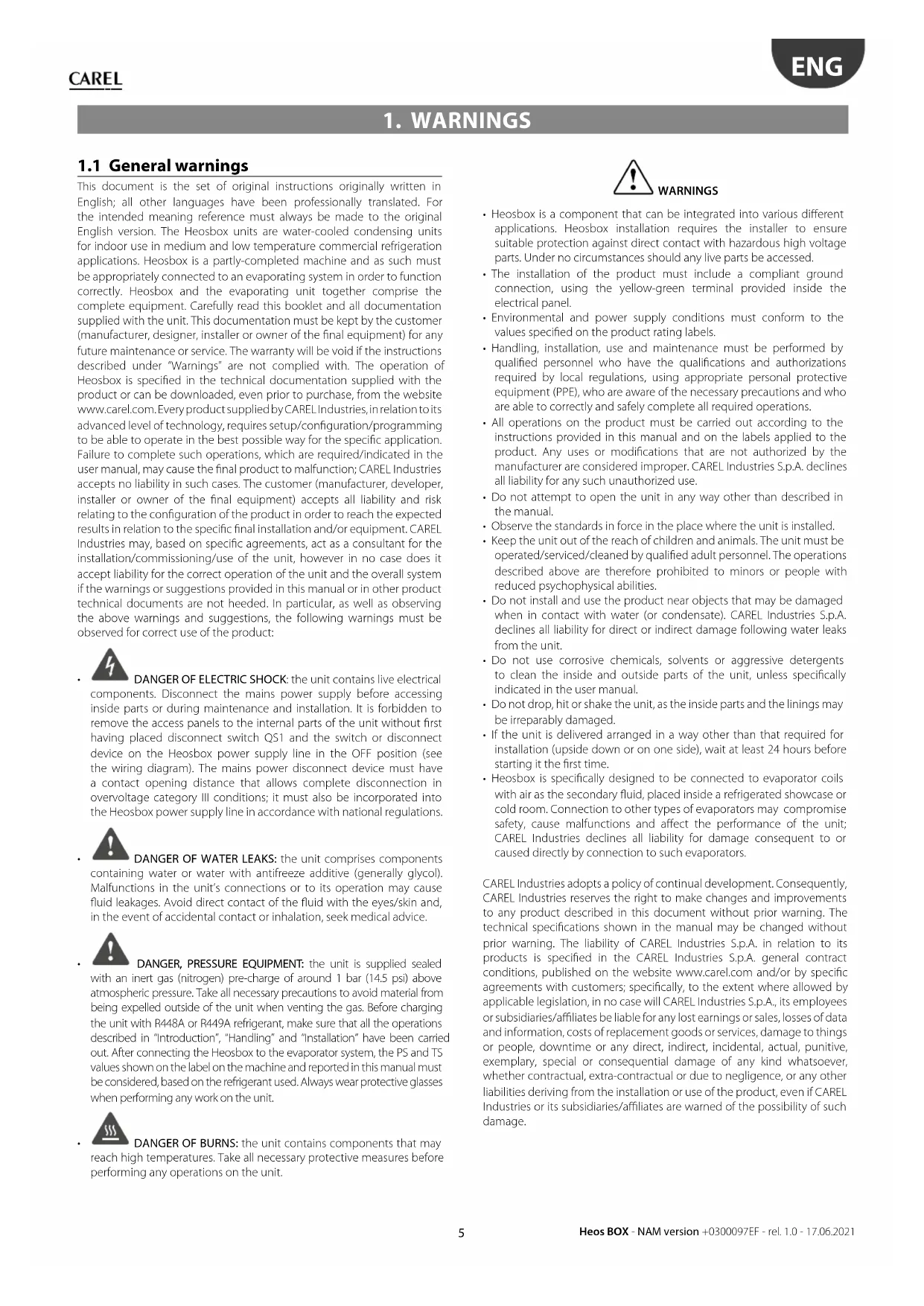
1. WARNINGS
1.1 General warnings
This document is the set of original instructions originally written in English; all other languages have been professionally translated. For the intended meaning reference must always be made to the original English version. The Heosbox units are water-cooled condensing units for indoor use in medium and low temperature commercial refrigeration applications. Heosbox is a partly-completed machine and as such must be appropriately connected to an evaporating system in order to function correctly. Heosbox and the evaporating unit together comprise the complete equipment. Carefully read this booklet and all documentation supplied with the unit. This documentation must be kept by the customer (manufacturer, designer, installer or owner of the final equipment) for any future maintenance or service. The warranty will be void if the instructions described under "Warnings" are not complied with. The operation of Heosbox is specified in the technical documentation supplied with the product or can be downloaded, even prior to purchase, from the website www.carel.com. Every product supplied by CAREL Industries, in relation to its advanced level of technology, requires setup/configuration/programming to be able to operate in the best possible way for the specific application. Failure to complete such operations, which are required/indicated in the user manual, may cause the final product to malfunction; CAREL Industries accepts no liability in such cases. The customer (manufacturer, developer, installer or owner of the final equipment) accepts all liability and risk relating to the configuration of the product in order to reach the expected results in relation to the specific final installation and/or equipment. CAREL Industries may, based on specific agreements, act as a consultant for the installation/commissioning/use of the unit, however in no case does it accept liability for the correct operation of the unit and the overall system if the warnings or suggestions provided in this manual or in other product technical documents are not heeded. In particular, as well as observing the above warnings and suggestions, the following warnings must be observed for correct use of the product:

DANGER OF ELECTRIC SHOCK: the unit contains live electrical elements. Disconnect the mains power supply before accessing parts or during maintenance and installation. It is forbidden to the access panels to the internal parts of the unit without first placed disconnect switch QS1 and the switch or disconnect on the Heosbox power supply line in the OFF position (see ng diagram). The mains power disconnect device must have act opening distance that allows complete disconnection in age category III conditions; it must also be incorporated into sbox power supply line in accordance with national regulations.

DANGER OF WATER LEAKS: the unit comprises components of water or water with antifreeze additive (generally glycol). Tions in the unit's connections or to its operation may cause kages. Avoid direct contact of the fluid with the eyes/skin and, vent of accidental contact or inhalation, seek medical advice.

DANGER, PRESSURE EQUIPMENT: the unit is supplied sealed inert gas (nitrogen) pre-charge of around 1 bar (14.5 psi) above eric pressure. Take all necessary precautions to avoid material from spelled outside of the unit when venting the gas. Before charging with R448A or R449A refrigerant, make sure that all the operations and in "Introduction", "Handling" and "Installation" have been carried by connecting the Heosbox to the evaporator system, the PS and TS down on the label on the machine and reported in this manual must be ordered, based on the refrigerant used. Always wear protective glasses performing any work on the unit.

DANGER OF BURNS: the unit contains components that may high temperatures. Take all necessary protective measures before ing any operations on the unit.

WARNINGS
- Heosbox is a component that can be integrated into various different applications. Heosbox installation requires the installer to ensure suitable protection against direct contact with hazardous high voltage parts. Under no circumstances should any live parts be accessed.
- The installation of the product must include a compliant ground connection, using the yellow-green terminal provided inside the electrical panel.
- Environmental and power supply conditions must conform to the values specified on the product rating labels.
- Handling, installation, use and maintenance must be performed by qualified personnel who have the qualifications and authorizations required by local regulations, using appropriate personal protective equipment (PPE), who are aware of the necessary precautions and who are able to correctly and safely complete all required operations.
- All operations on the product must be carried out according to the instructions provided in this manual and on the labels applied to the product. Any uses or modifications that are not authorized by the manufacturer are considered improper. CAREL Industries S.p.A. declines all liability for any such unauthorized use.
- Do not attempt to open the unit in any way other than described in the manual.
- Observe the standards in force in the place where the unit is installed.
- Keep the unit out of the reach of children and animals. The unit must be operated/serviced/cleaned by qualified adult personnel. The operations described above are therefore prohibited to minors or people with reduced psychophysical abilities.
- Do not install and use the product near objects that may be damaged when in contact with water (or condensate). CAREL Industries S.p.A. declines all liability for direct or indirect damage following water leaks from the unit.
- Do not use corrosive chemicals, solvents or aggressive detergents to clean the inside and outside parts of the unit, unless specifically indicated in the user manual.
- Do not drop, hit or shake the unit, as the inside parts and the linings may be irreparably damaged.
- If the unit is delivered arranged in a way other than that required for installation (upside down or on one side), wait at least 24 hours before starting it the first time.
- Heosbox is specifically designed to be connected to evaporator coils with air as the secondary fluid, placed inside a refrigerated showcase or cold room. Connection to other types of evaporators may compromise safety, cause malfunctions and affect the performance of the unit; CAREL Industries declines all liability for damage consequent to or caused directly by connection to such evaporators.
CAREL Industries adopts a policy of continual development. Consequently, CAREL Industries reserves the right to make changes and improvements to any product described in this document without prior warning. The technical specifications shown in the manual may be changed without prior warning. The liability of CAREL Industries S.p.A. in relation to its products is specified in the CAREL Industries S.p.A. general contract conditions, published on the website www.carel.com and/or by specific agreements with customers; specifically, to the extent where allowed by applicable legislation, in no case will CAREL Industries S.p.A., its employees or subsidiaries/affiliates be liable for any lost earnings or sales, losses of data and information, costs of replacement goods or services, damage to things or people, downtime or any direct, indirect, incidental, actual, punitive, exemplary, special or consequential damage of any kind whatsoever, whether contractual, extra-contractual or due to negligence, or any other liabilities deriving from the installation or use of the product, even if CAREL Industries or its subsidiaries/affiliates are warned of the possibility of such damage.
PLEASE READ AND KEEP
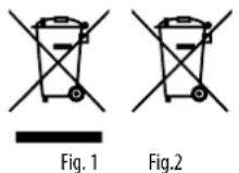
With reference to European Union directive 2012/19/EU issued on 4 July 2012 and related national legislation, please note that:
- Waste Electrical and Electronic Equipment (WEEE) cannot be disposed of as municipal waste but must be collected separately so as to allow subsequent recycling, treatment or disposal, as required by law;
- users are required to take Electrical and Electronic Equipment (EEE) at end-of-life, complete with all essential components, to the WEEE collection centres identified by local authorities. The directive also provides for the possibility to return the equipment to the distributor or retailer at end-of-life if purchasing equivalent new equipment, on a one-to-one basis, or one-to-zero for equipment less than 25 cm on their longest side;
- this equipment may contain hazardous substances: improper use or incorrect disposal of such may have negative effects on human health and on the environment;
- the symbol (crossed-out wheeled bin – Fig.1) even if, shown on the product or on the packaging, indicates that the equipment must be disposed of separately at end-of-life;
- if at end-of-life the EEE contains a battery (Fig. 2), this must be removed following the instructions provided in the user manual before disposing of the equipment. Used batteries must be taken to appropriate waste collection centres as required by local regulations;
- in the event of illegal disposal of electrical and electronic waste, the penalties are specified by local waste disposal legislation.
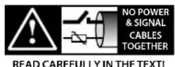
Separate as much as possible the probe and digital input cables from cables to inductive loads and power cables, so as to avoid possible electromagnetic disturbance. Never run power cables (including the electrical panel cables) and signal cables in the same conduits.

IMPORTANT WARNINGS
This product is to be integrated and/or incorporated into the final apparatus or equipment. Verification of conformity to the laws and technical standards in force in the country where the final apparatus or equipment will be operated is the manufacturer's responsibility. Before delivering the product, Carel has already completed the checks and tests required by the relevant European directives and harmonized standards, using a typical test setup, which however cannot be considered as representing all possible conditions of the final installation.
DECLARATION OF CONFORMITY
The CAREL Heos box is in compliance with current regulation: UL 1995/2015
WARRANTY ON MATERIALS
See the document "Warranty terms and conditions", which should be kept carefully together with this manual and all other technical documentation delivered with the Heosbox unit.
APPROVAL
The quality and safety of CAREL Industries S.p.A. HQ products are guaranteed by the ISO 9001 certified design and production system.
2. INTRODUCTION
2.1 Heosbox description
The Heosbox series units are water-cooled condensing units for medium (MT) and low (LT) temperature commercial refrigeration applications, designed and manufactured in compliance with specific current European and international product standards. Heosbox can be coupled to a wide range of refrigerated showcases and cold rooms. The modular solution offers considerable benefits in terms of simple installation, handling, maintenance and interchangeability. Heosbox is a partly-completed machine and as such must be appropriately connected to a system fitted with an evaporator. The unit therefore essentially comprises: a partial refrigerant circuit and an electrical panel with power distribution and control systems. Being a partly-completed unit, Heosbox is supplied without refrigerant, however pre-charged with nitrogen for safe storage.
Heosbox must be installed in the evaporator system and charged with refrigerant in compliance with the regulations in force, otherwise the warranty will be void.
Heosbox is specifically designed to be used with medium and low temperature showcases with air-cooled evaporator coils and connected to water loop condensation heat transfer systems. The unit can efficiently control the temperature inside the refrigerated showcase through the integrated sophisticated modulating controller and connection to the external water loop. The equipment and instruments for managing the condensation heat transfer water system are not supplied with Heosbox.
The control software is described in the HEOS manual, Carel part number "+0300078EN".
2.2 Heosbox unit configurations
The Heosbox series units differ in terms of type of application, as shown in Tab. 2.a.
Design Conformity Applications available
| North America (NAM) | UL 1995/2015 | Single Evaporator, Medium and Low Temperature (SE-MT/LT)Multi-Evaporator, Medium Temperature (ME-MT)Multi-Evaporator, Low Temperature (ME-LT) |
Tab. 2.a
There are three applications available and these differ according to the number of evaporators that the unit must serve (up to five showcases in multi-evaporator configuration) and the expected control temperature (medium or low temperature showcases), as shown below in tab. 2.b.

Caution: the default SW configuration of the multi-evaporator operates a simultaneous defrost on all evaporators only when the compressor stops (parameter d2 = 1 , start and end). This condition is present with the specific electrical panel construction of Heosbox that is the simultaneous activation of the compressor and defrost heaters. Modification of default value of the d2 parameter can cause a system during the defrost operation.
Application Part number|Description Notes
| Single evaporator (SE), Medium and low temperature (MT/LT), NAM design (see Fig. 2.a) | HB1US**M*W1** Unit complete with refrigerant circuit, without electronic expansion valve, electrical panel and probe kit (included inside the panel) for complete control of a medium and low temperature showcase. | The units can operate in a stand-alone configuration or as part of a Main/Secondary sub-network where the different showcases, each with an independent refrigerant circuit, can carry out coordinated actions as specified in the control manual "+0300078EN".No electronic expansion valve is included. This must be ordered separately, after having been suitably sized according to the Heosbox version and the type of evaporator it will be combined with. Carel Industries S.p.A. can provide support for the sizing of the electronic expansion valve, however cannot be held liable for the design or installation of the aforementioned expansion valves if the sizing, positioning, installation and operating criteria described in this manual and in the documents supplied with the electronic expansion valves have not been complied with. |
| Multi-evaporator (ME), medium temperature (MT) and low temperature (LT), NAM design (see Fig. 2.b) | HB1US**E*W1** HB1US**D*W1** | The Heos controller can manage up to five multi-evaporator Secondary units, therefore a total of six evaporators. For best control, Carel Industries S.p.A. recommends a maximum of 3 multi-evaporator units.Carel Industries S.p.A. can provide support for the design of the multi-evaporator configuration, however cannot be held liable in any way for the design itself or the installation.No electronic expansion valve is included. This must be ordered separately, after having been suitably sized according to the Heosbox version and the type of evaporator it will be combined with. Carel Industries S.p.A. can provide support for the sizing of the electronic expansion valve, however cannot be held liable for the design or installation of the aforementioned expansion valves if the sizing, positioning, installation and operating criteria described in this manual and in the documents supplied with the electronic expansion valves have not been compliedwith. |
Tab. 2.b
UNIT PLUS MT OR LT SINGLE EVAPORATOR
flowchart
graph TD
    A["Supervisor network"] --> B["Main/Secondary multi evaporator network"]
    B --> C["BMS"]
    A --> D["Controller with sensors"]
    D --> E["Controller with sensors"]
    E --> F["Controller with sensors"]
    F --> G["Controller with sensors"]
    G --> H["Controller with sensors"]
    H --> I["Controller with sensors"]
    I --> J["Controller with sensors"]
    J --> K["Controller with sensors"]
    K --> L["Controller with sensors"]
    L --> M["Controller with sensors"]
    M --> N["Controller with sensors"]
    N --> O["Controller with sensors"]
    O --> P["Controller with sensors"]
    P --> Q["Controller with sensors"]
    Q --> R["Controller with sensors"]
    R --> S["Controller with sensors"]
    S --> T["Controller with sensors"]
    T --> U["Controller with sensors"]
    U --> V["Controller with sensors"]
    V --> W["Controller with sensors"]
    W --> X["Controller with sensors"]
    X --> Y["Controller with sensors"]
    Y --> Z["Controller with sensors"]
Fig. 2.b
2.3 Models and part number structure
The following Heosbox models are available:
| Application | Built-in compressor P/N available with NAM design | |
| Electrical protection with circuit breakers | ||
| Single Evaporator (SE) Medium and low Temperature (MT/LT) | DA91 HB1US03M0W1A0 | |
| DA130 HB1US04M0W1A0 | ||
| DA220 HB1US06M0W1A0 | ||
| DA330 HB1US08M0W1B0 | ||
| DA420 HB1US08M3W1B0 | ||
| Multi-Evaporator (ME) Medium Temperature (MT) | DA91 HB1US03E0W1A0 | |
| DA130 HB1US04E0W1A0 | ||
| DA220 HB1US06E0W1A0 | ||
| DA330 HB1US08E0W1B0 | ||
| DA420 HB1US08E3W1B0 | ||
| Multi Evaporator (ME) Low Temperature (LT) | DA91 HB1USL0D0W1A0 | |
| DA130 HB1USL1D0W1A0 | ||
| DA220 HB1US02D0W1A0 | ||
| DA330 HB1US03D0W1B0 | ||
| DA420 HB1US02D3W1B0 | ||
Tab. 2.c
Structure options
| HB * * * * * * * * | ** | ||||||||
| Family prefix | 3 | 4-5 | 6-7 | 8 | 9 | 10 | 11 | 12 | 13 |
| Pos. | Meaning | Opt. | Description |
| 3 | Product family | 1 | Family 1 (project C779) - uPCII - without plastic cover |
| 4-5 | Customization | US | Customized version for CUS (MVP) |
| 6-7 | Cooling Capacity | ** | CC: 1-99 kWt*(ref. MT: Tev=-10°C Tcond= 40°C), according to EN13215.*(ref. LT: Tev=-35°C Tcond= 40°C) according to EN13215 |
| L0 | LT 0-0.9 kWt | ||
| L1 | LT 1-1.4 kWt | ||
| 02 | 1.5-2.4 kWt | ||
| 03 | 2.5-3.4 kWt | ||
| 04 | 3.5-4.4 kWt | ||
| 05 | 4.5-5.4 kWt | ||
| 06 | 5.5-6.4 kWt | ||
| 07 | 6.5-7.4 kWt | ||
| 08 | 7.5-8.4 kWt | ||
| 09 | 8.5-9.4 kWt | ||
| 10 | 9.5-10.4 kWt | ||
| 11 | 10.5-11.4 kWt | ||
| 8 | Unit Arrangement | E | MT Multi Evaporator |
| D | LT Multi Evaporator | ||
| M | MT single evaporator | ||
| 9 | Refrigerant Type | 0 | R410A - R448A - R449ANotice: R448A - R449A only with digits 4-5 "US" |
| 3 | R448A - R449A only | ||
| 10 | Air/Water cooled | W | Water cooled (Water loop System) |
| 11 | Power Supply and Inverter type | 1 | 1ph Inverter air cooled with plastic cover PEC |
| 12 | Electrical Panel Type | A | DA91, DA130, DA220 - 12A, 1 ph - NAM - R448A - R449A, 60Hz |
| B | DA330, DA420 - 18A, 1 ph - NAM - R448A - R449A, 60Hz | ||
| 13 | Packaging | 0 | Single package |
Tab. 2.d
2.4 Technical specifications
Technical specifications for NAM versions
| MT/LT Single Evaporator and MT Multi-Evaporator, NAM version - Medium Temperature operation | ||||||
| Family HB1US | ||||||
| Type: MT/LT Single Evaporator 03M 04M 06M 08M 08M | ||||||
| Type: MT Multi-Evaporator 03E 04E 06E 08E 08E | ||||||
| Standard configuration 0W1A0 0W1A0 0W1A0 0W1B0 3W1B0 | ||||||
| Power supply | V 200-220 200-220 | 200-220 200-220 200-220 | ||||
| Ph 2+N 2+N 2+N 2+N 2+N | ||||||
| Hz | 50-60Hz | 50-60Hz | 50-60Hz | 50-60Hz | 50-60Hz | |
| Compressor current draw - R448A - R449A | [A] | 5.2 | 7.4 | 12.6 | 16.5 | 21.1 |
| Max unit current draw - R448A - R449A (1) | [A] | 7.2 | 9.4 | 14.6 | 18.5 | 23.1 |
| MCA (4) R448A - R449A | [A] | 10.8 | 11.8 | 18.2 | 23.4 | 27.5 |
| MOP (5) R448A - R449A | [A] | 15 | 15 | 25 | 45 | 45 |
| MinOP (6) R448A - R449A | [A] | 15 | 15 | 20 | 30 | 30 |
| Cooling capacity with R448A - R449A (2) | [kW] | 1.9 | 2.7 | 4.1 | 6.1 | 7.9 |
| Sound power | [dB(A)] | <65 | <65 | <65 | <65 | <65 |
| Condenser water flow-rate (3) | [l/min] / [US gpm] | 11.5/3.04 | 17.8/4.7 | 24.4/6.45 | 46.9/12.39 | 47/12.42 |
| Condenser pressure drop (3) | [kPa] / [psi] | 28.4/4.12 | 30.8/4.47 | 30.5/4.42 | 27.9/4.05 | 28.1/4.07 |
| Refrigerant side - Max allowable pressure - HP | [Bar] / [psi] | 40/580 | 40/580 | 40/580 | 40/580 | 40/580 |
| Refrigerant side - Max allowable pressure - LP | [bar] / [psi] | 22/319 | 22/319 | 22/319 | 22/319 | 22/319 |
| Refrigerant side - Max allowable temperature | [°C] / [°F] | 100/212 | 100/212 | 100/212 | 100/212 | 100/212 |
| Safety valve opening pressure | [Bar] / [psi] | 40/580 | 40/580 | 40/580 | 40/580 | 40/580 |
| Pressure switch opening pressure (7) | [Bar] / [psi] | 35/508 | 35/508 | 35/508 | 35/508 | 35/508 |
| Water side - Max operating pressure | [bar] / [psi] | 15.9/231 | 15.9/231 | 15.9/231 | 15.9/231 | 15.9/231 |
| Water side - Max operating temperature | [°C] / [°F] | 48/118.4 | 48/118.4 | 48/118.4 | 48/118.4 | 48/118.4 |
Tab. 2.e
MT/LT Single Evaporator unit and LT Multi Evaporator unit, NAM version - Low Temperature operation
| Family HB1US | ||||||
| Type: MT/LT Single Evaporator 03M 04M 06M 08M 08M | ||||||
| Type: LT Multi Evaporator | L0D | L1D | 02D | 03D | 02D | |
| Standard configuration 0W1A0 0W1A0 0W1A0 0W1B0 3W1B0 | ||||||
| Power supply | V 200-220 200-220 | 200-220 200-220 200-220 | ||||
| Ph 2+N 2+N 2+N 2+N 2+N | ||||||
| Hz | 50-60Hz | 50-60Hz | 50-60Hz | 50-60Hz | 50-60Hz | |
| Compressor current draw - R448A - R449A | [A] | 5.2 | 7.4 | 12.6 | 16.5 | 21.1 |
| Max unit current draw - R448A - R449A (1) | [A] | 7.2 | 9.4 | 14.6 | 18.5 | 23.1 |
| MCA (4) R448A - R449A | [A] | 10.8 | 11.8 | 18.2 | 23.4 | 27.5 |
| MOP (5) R448A - R449A | 15 | 15 | 25 | 45 | 45 | |
| MinOP (6) R448A - R449A | [A] | 15 | 15 | 20 | 30 | 30 |
| Cooling capacity with R448A - R449A (2) | [kW] | 0.5 | 0.7 | 1.1 | 1.6 | 2.0 |
| Sound power | [dB(A)] | <65 | <65 | <65 | <65 | <65 |
| Condenser water flow-rate (3) | [l/min] / [US qpm] | 8.06/2.13 | 8.4/2.12 | 11.5/3.04 | 17.8/4.70 | 24.5/6.47 |
| Condenser pressure drop (3) | [kPa] / [psi] | 28.4/4.12 | 28/4.06 | 28.5/4.13 | 30.7/4.45 | 30.7/4.45 |
| Refrigerant side - Max allowable pressure - HP | [bar] / [psi] | 40/580 | 40/580 | 40/580 | 40/580 | 40/580 |
| Refrigerant side - Max allowable pressure - LP | [bar] / [psi] | 22/319 | 22/319 | 22/319 | 22/319 | 22/319 |
| Refrigerant side - Max allowable temperature | [°C] / [°F] | 100/212 | 100/212 | 100/212 | 100/212 | 100/212 |
| Safety valve opening pressure | [Bar] / [psi] | 40/580 | 40/580 | 40/580 | 40/580 | 40/580 |
| Pressure switch opening pressure (7) | [Bar] / [psi] | 35/508 | 35/508 | 35/508 | 35/508 | 35/508 |
| Water side - Max operating pressure | [bar] / [psi] | 15.9/231 | 15.9/231 | 15.9/231 | 15.9/231 | 15.9/231 |
| Water side - Max operating temperature | [°C] / [°F] | 48/118.4 | 48/118.4 | 48/118.4 | 48/118.4 | 48/118.4 |
Tab. 2.f

Notice:
(1) When calculating the maximum current draw, it is assumed that the defrost heaters and compressor never operate simultaneously as expected by the construction of the electrical panel. Therefore, this value includes the Heos high efficiency showcase controller and all of the control signals of the auxiliary loads (see paragraph 2.7). Pay special care with the multi-evaporator configuration (see page 7).
(2) The nominal conditions refer to AHRI Standard 540:
- MT Tevap=-6.5°C (20.3°F)
- Tcond=43.5°C (110.3°F)
- LT Tevap=-31.5°C (-24.7°F)
- Tcond=40.5°C (104.9°F)
• superheat=10K
^13 LT Tcvap=-35°C (-31°F)
Tcond=40°C (104°F);
superheat = 10K,
subcooling = 0K.
The data refer to a water flow rate containing 20% antifreeze (ethylene glycol) additive by volume. By varying the percentage by volume of antifreeze additive (ethylene glycol) in the water circuit, the reported performance and pressure drop will vary from the values shown in the tables.
^40 Minimum circuit current for sizing the cables.
15 Maximum current for overcurrent protection.
(e) Minimum current for overcurrent protection.
^21 Manual reset of the pressure switch at 29bar / 421psi.
2.5 Other specifications
• Refrigerant leakage <2 g/year of R410A at 45 barg.
- If there are components in the water circuit with a lower PS or TS, the entire water circuit will be downgraded to the lowest PS or TS of all its components. Verify the transport and operating conditions for correct operation of the unit.
2.6 Operating limits
- Units for indoor use. IP20 ingress protection on outer casing.
- Minimum/maximum air temperature for indoor operation: +5/+40°C (+41/+104°F), RH < 80% non-condensing.
- Minimum/maximum temperature of the glycol mixture entering the condenser, at the nominal flow-rate specified in the "Technical Specifications" tables: +5/+48°C (+41/+118.4°F).
- Minimum/maximum saturated temperature at evaporation pressure: -35^ / + 3^(-31^ / + 37.4^) ;
T inlet water [°C / °F] T evap MT [°C / °F] T evap LT [°C / °F]
| 5^ ≤ T ≤ 45^ C | ≤ 3^ C | ≥-35°C |
| 41^ ≤ T ≤ 113^ F | ≤37.4°F | ≥-31°F |
| 45^ ≤ T ≤ 48^ C | ≤ - 7^ C | ≥-35°C |
| 113^ < T ≤ 118.4^ F | ≤19.4°F | ≥-31°F |
Tab. 2.g
- Altitude up to 2000m (6562 ft) above sea level
- Minimum/Maximum storage/transport temperature with nitrogen (N _2 ) charge: -20/+70°C (-4/+158°F).
2.7 Electrical specifications of the auxiliary loads

Caution: the protections supplied inside the unit's electrical panel are intended exclusively to protect the load against short circuits. Additional protections (for example, overload) are the installer's responsibility.

Notice: some wiring inputs provided with cable glands; electrical connections and cable gland tightening to be performed by the installer.
The following auxiliary electrical loads are managed by the electric panel:
| No. | Description of the auxiliary load | Type of output^(1) | Nominal frequency (2) | Nominal voltage |
| - [Hz] [V] | ||||
| 1 | Defrost heaters Power supply 60 208 | (1) | ||
| 2 | Defrost heaters Control signal 60 24 | |||
| 3 | Light | Control signal 60 24 | ||
| 4 | Evaporator fan | Control signal 60 24 | ||
| 5 | Rail heaters | Control signal 60 24 | ||
Tab. 2.h
(1) Range 200-240V;
(2) Range 50-60Hz;
The power supply provides to outputs from 2 to 5 is a total of 20 VA. If the electrical power drawn by outputs from 2 to 5 exceeds 20 VA, a malfunction of the electronic controller may occur.
The table below reports the maximum allowable defrost heater amperage draw that is never greater than the compressor amperage draw for each model.
MT/LT Single Evaporator and MT/LT Multi-Evaporator, - Fig. 2.a
| Family | HB1US | |||||
| MT/LT Single Evaporator size | 03M | 04M | 06M | 08M | 11M | |
| MT Multi-Evaporator size | 03E | 04E | 06E | 08E | 11E | |
| LT Multi-Evaporator size | L0D | L1D | 02D | 03D | 03D | |
| Standard configuration | 0W1A0 | 0W1A0 | 0W1A0 | 0W1B0 | 3W1B0 | |
| Max current | A | 5.2 | 7.4 | 12.6 | 16.5 | 20 |
Tab. 2.i
2.8 Dimensions and weights
The unit, regardless of the type of application and the cooling capacity it can supply, has a self-supporting pickled and painted sheet metal containment structure, RAL9005P, with the following dimensions and weights.
MT/LT Single Evaporator and MT/ LT Multi-Evaporator, NAM version - Fig. 2.b
| Family | HB1US | |||||
| MT Single Evaporator size | 03M | 04M | 06M | 08M | 11M | |
| MT Multi-Evaporator size | 03E | 04E | 06E | 08E | 11E | |
| LT Single Evaporator size | L0L | L1L | 02L | 03L | 03L | |
| Standard configuration | 0W1A0 | 0W1A0 | 0W1A0 | 0W1B0 | 3W1B0 | |
| L | mm (in) | 284 (48.19) | ||||
| W | mm (in) | 520 (20.47) | ||||
| H | mm (in) | 250 (9.84) | ||||
| Weight | kg | 51.5 | 53.5 | 59.7 | 70.5 | 75.6 |
| L with packaging ^(2) | mm (in) | 280 (50.39) | ||||
| W with packaging ^(2) | mm (in) | 590 (23.23) | ||||
| H with packaging ^(2) | mm (in) | 405 (15.94) | ||||
| Weight with packaging ^(2) | kg | +12 | +12 | +12 | +12 | +12 |
Tab. 2.j
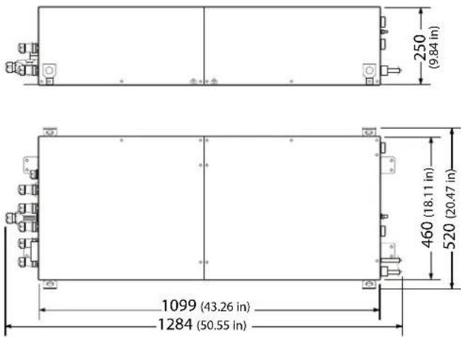
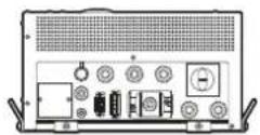
Fig. 2.c
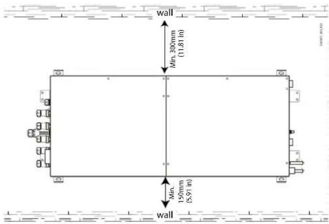
The figure below shows the clearance from surfaces (3).
Lateral view

text_image
wall Min. 150mm (5.91 in) wallFig. 2.d
Top view
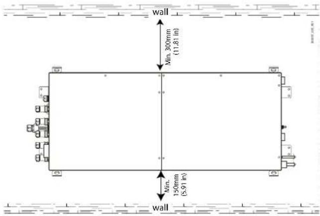
text_image
wall Min. 300mm (11.81 in) Min- 150mm (5.91 in) wallFig. 2.e

Notice:
(1) Heosbox cannot be installed in enclosed spaces where no natural ventilation can be ensured, otherwise there will be a decline in performance and the unit will probably malfunction. Furthermore, adequate clearance must be provided in all directions, except for underneath the support base, so as to ensure correct operation of the unit.
(2) The unit's packaging is made with wooden pallets and a cardboard box fixed with plastic straps. The packages can be stacked one on top of the other, up to a maximum of three, as long as the unit is kept in the correct position (see the symbols printed on the packaging). Note, there is residual risk of the load falling from the transport vehicle, if these limits are exceeded.
(3) Clearance in other directions not shown in the figure: 300 mm (11.81 in).
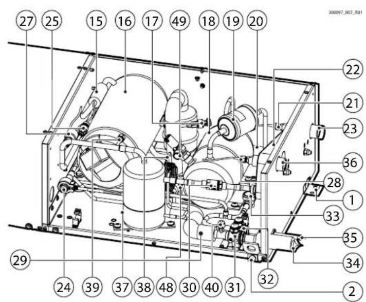
2.9 Refrigeration unit components
The following table describes the individual components making up the unit.
Ref. Position Description
| 1 | Fig.2.g Unit fixing tabs | |
| 2 | Fig.2.g Unit lifting corners | |
| 3 | Fig.2.h Electric panel ventilation air intake grille | |
| 4 | Fig.2.h Electric panel ventilation air exhaust grille | |
| 12 | Fig.2.h W-Fi gateway kit cable gland | |
| 13 | Fig.2.h RJ485 port for controller display | |
| 14 | Fig.2.h Electrical panel main switch | |
| 15 | Fig.2.f & 2g Discharge temperature probe | |
| 16 | Fig.2.f & 2g Compressor | |
| 17 | Fig.2.f & 2g Suction pressure transducer | |
| 18 | Fig.2.f & 2g Liquid receiver | |
| 19 | Fig.2.f & 2g Filter-drier | |
| 20 | Fig.2.f & 2g Liquid temperature probe | |
| 21 | Fig.2.f & 2g Water inlet temperature probe | |
| 22 | Fig.2.f & 2g Condenser | |
| 23 | Fig.2.f & 2g Water inlet connection | |
| 24 | Fig.2.f & 2g Liquid injection valve | |
| 25 | Fig.2.f & 2g Discharge pressure transducer | |
| 27 | Fig.2.f & 2g Safety pressure switch | |
| 28 | Fig.2.f & 2g Water outlet temperature probe | |
| 29 | Fig.2.g Fig.2.g Suction temperature probe | |
| 30 | Fig.2.f & 2g Check valve | |
| 31 | Fig.2.f & 2g Refrigerant inlet shut-off valve | |
| 32 | Fig.2.f & 2g Refrigerant outlet shut-off valve | |
| 33 | Fig.2.f & 2g Liquid/moisture indicator | |
| 34 | Fig.2.f & 2g Refrigerant inlet connection | |
| 35 | Fig.2.f & 2g Refrigerant outlet connection | |
| 36 | Fig.2.f & 2g Water outlet connection | |
| 37 | Fig.2.f & 2.g Oil separator | |
| 38 | Fig.2.f & 2.g Capillary tube | |
| 39 | Fig.2.f & 2g Discharge pressure port | |
| 40 | Fig.2.f & 2g Suction pressure port | |
| 43 | Fig.2.f & 2g Sensor terminals | |
| 45 | Fig.2.h W-Fi gateway terminals | |
| 46 | Fig.2.h Inverter | |
| 47 | Fig.2.h Free cable gland | |
| 48 | Fig.2.f & 2g Liquid line pressure port | |
| 49 | Fig.2.f & 2.g Safety valve | |
| 50 | Fig.2.g Serial connectors | |
| 52 | Fig.2.h Transformer | |
| 53 | Fig.2.h Electrical protections | |
| 54 | Fig.2.h Heds controller |
Tab. 2.k

Notice:
^11 available only on single evaporator units
^2 available only on multi-evaporator units
^3 for NAM versions only
^34 NAM versions as standard use circuit breakers.
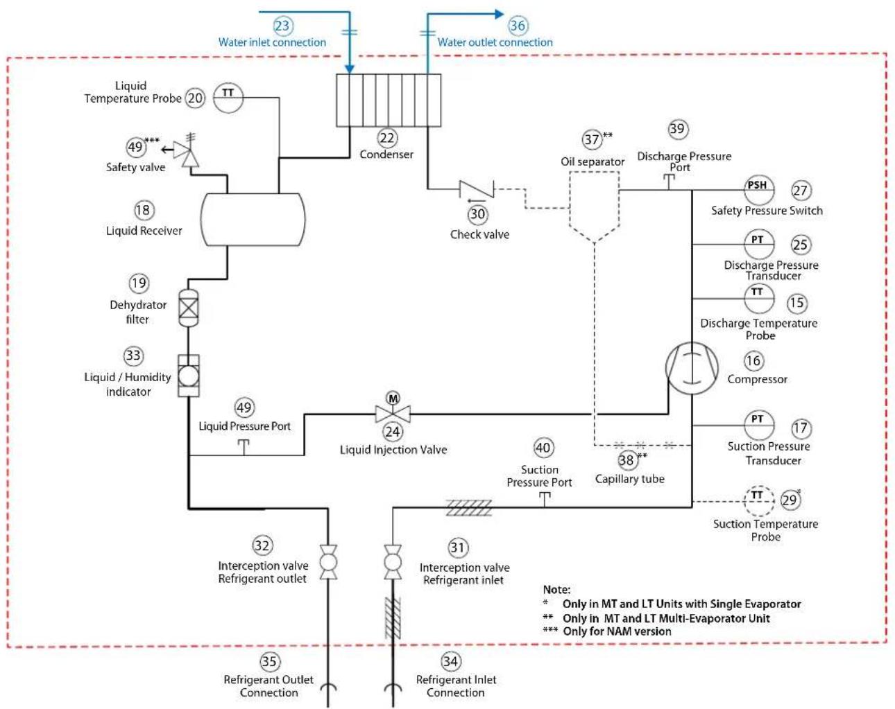
2.10 Refrigerant circuit diagram
flowchart
graph TD
    A["Liquid Temperature Probe 20"] --> B["Condenser"]
    C["Safety valve 49***"] --> B
    D["Liquid Receiver 18"] --> B
    E["Dehydrator filter 19"] --> B
    F["Liquid / Humidity indicator 33"] --> B
    G["Interception valve Refrigerant outlet 32"] --> H["Liquid Pressure Port 49"]
    I["Interception valve Refrigerant inlet 31"] --> J["Liquid Injection Valve 24"]
    K["Refrigerant Outlet Connection 35"] --> L["Refrigerant Inlet Connection 34"]
    M["Check valve 30"] --> N["Oil separator 37**"]
    O["Capillary tube 40"] --> P["Suction Pressure Port 38**"]
    Q["Discharge Pressure Transducer PT 25"] --> R["Discharge Pressure Switch 27"]
    S["Discharge Temperature Probe 15"] --> T["Discharge Pressure Transducer"]
    U["Compressor 16"] --> V["Compressor"]
    W["Suction Pressure Transducer PT 17"] --> X["Suction Temperature Probe 29"]
    Y["Water inlet connection 23"] --> Z["Water outlet connection 36"]
    AA["Water inlet connection 39"] --> AB["Discharge Pressure Port 39"]
    AC["Water inlet connection 40"] --> AD["Suction Pressure Port 40"]
    AE["Water inlet connection 49"] --> AF["Suction Pressure Port 49"]
    AG["Water inlet connection 50"] --> AH["Suction Pressure Port 50"]
Fig. 2.f
Refrigerant circuit
text_image
Technical diagram of an industrial machine with numbered components for identificationFig. 2.g
| Ref. | Description | Ref. | Description |
| 1 | Unit fixing tabs | 29 (1) | Suction temperature probe |
| 2 | Unit lifting corners | 30 | Check valve |
| 15 | Discharge temperature probe | 31 | Refrigerant inlet shut-off valve |
| 16 | Compressor | 32 | Refrigerant outlet shut-off valve |
| 17 | Suction pressure transducer | 33 | Liquid/moisture indicator |
| 18 | Liquid receiver | 34 | Refrigerant inlet connection |
| 19 | Filter-drier | 35 | Refrigerant outlet connection |
| 20 | Liquid temperature probe | 36 | Water outlet connection |
| 21 | Water inlet temperature probe | 37 (2) | Oil separator |
| 22 | Condenser | 38 (2) | Capillary tube |
| 23 | Water inlet connection | 39 | Discharge pressure port |
| 24 | Liquid injection valve | 40 | Suction pressure port |
| 25 | Discharge pressure transducer | 48 | Liquid line pressure port |
| 27 | Safety pressure switch | 49 (3) | Safety valve |
| 28 | Water outlet temperature probe | ||

Notice:
^11 available only on single evaporator units;
^12 available only on multi-evaporator units;
for NAM versions only.
Tab. 2.1
2.11 Electrical panel
NAM-ELECTRICAL PANEL (SINGLE EVAP & MULTIEVAP)
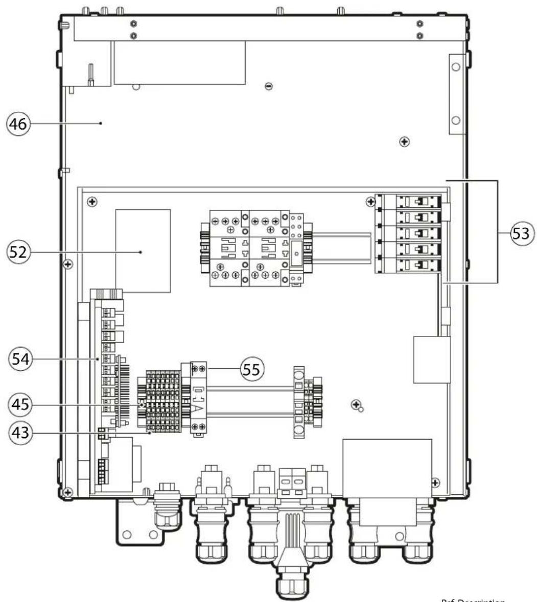
text_image
46 52 53 54 55 45 43 Ref. Desription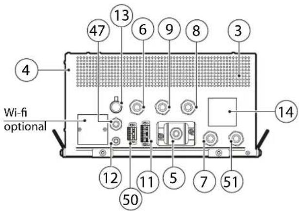
text_image
4 13 6 9 8 3 47 6 14 12 11 5 7 51 50 Wi-fi optionalRef. Description
3 Electric panel ventilation air intake grille
4 Electric panel ventilation air exhaust grille
5 Electrical panel power input
6 Defrost output 208 V
7 Anti-sweat output 24 V
8 Evap. fan output 24 V
9 Light output 24 V
11 Sensor input
12 Wi-Fi gateway kit cable gland
13 RJ485 port for controller display
14 Electrical panel main switch
43 Probe, Digital output and Safety thermostat
45 Wi-Fi gateway terminals
46 Inverter
47 Expansion valve
50 Serial connectors
51 Defrost output 24 V
52 Transformer
53 Circuit breakers
54 Heos controller
55 Gateway wi-fi power supply
Tab. 2.m
In the single evaporator versions, the panel is supplied together a with kit of three probes, P/N NTC060HP00: these must be installed to monitor the air inlet temperature, the evaporator coil air outlet temperature and the defrost temperature. In the multi-evaporator versions, in addition to the three probes mentioned above, there is also one probe P/N NTC060HF01 for the compressor suction temperature.
It should be noted that the panel has four digital inputs:
- Input #1: intended for a possible door switch
- Inputs #2 to #4: free to be configured by the user.
NAM electrical panel sensor terminal block
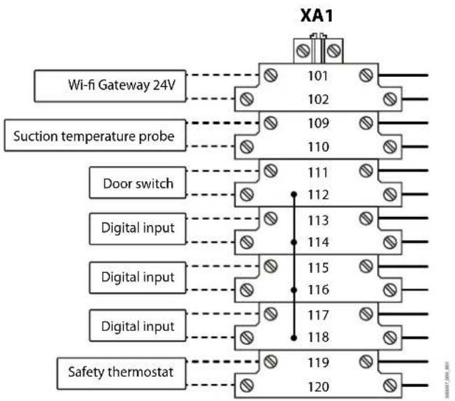
flowchart
graph TD
    A["Wi-fi Gateway 24V"] --> B["101"]
    A --> C["102"]
    D["Suction temperature probe"] --> E["109"]
    D --> F["110"]
    G["Door switch"] --> H["111"]
    G --> I["112"]
    J["Digital input"] --> K["113"]
    J --> L["114"]
    M["Digital input"] --> N["115"]
    M --> O["116"]
    P["Digital input"] --> Q["117"]
    P --> R["118"]
    S["Safety thermostat"] --> T["119"]
    S --> U["120"]
Fig. 2.i

Notice: the correct terminal block layouts for the electrical connections are shown on the wiring diagram for each individual Heosbox unit and each Multi-Evaporator Kit.
3. HANDLING
3.1 Opening the packaging
- Check that the unit is intact upon delivery and notify the carrier immediately, in writing, of any damage that may be due to improper or negligent transport;
- move the unit to the place of installation before removing it from the packaging, lifting the package with the wooden pallet. Use lifting equipment, avoid handling the load manually. Residual risk of the unit falling during installation if an improper hoisting device/accessory is used;
- position the unit near the place where it is to be installed (still packaged on the pallet);
- remove the packaging, open the cardboard box and remove the screws fixing it to the pallet.
It is recommended to store the packaging (cardboard box, pallets and bolts) in a dry environment so that they can be reused.
3.2 Positioning the unit
The unit must be firmly anchored to the system it is part of using the "L" shaped anchoring sections on the sides of the structure.
The unit must be positioned so as to allow the following operations:
- opening and removal of the front panels on the refrigerant compartment and electrical compartment;
- accessibility to the internal parts for checks and maintenance (observe the clearances);
- connection of the refrigerant supply lines;
- connection of the water supply lines;
• power and control electrical connections;
• temperature probe and optional kit connections; - communication serial line connections.
The unit must be positioned in the immediate vicinity of the single showcase served (single evaporator unit) or in a favourable position for correct distribution of the refrigerant to the entire group of showcases (Multi-Evaporator unit), ensuring both the minimum length of piping between the unit and the evaporator, and oil return to the unit. To ensure correct operation of the product, it should be installed on top of the showcase on a flat surface, in a suitable position so that the weight of the unit is supported by the showcase. The showcase must be designed to support the weight of the unit when operating.
Heosbox can also be installed on the floor, observing the clearances and making sure that there is natural ventilation to the unit. Always avoid positioning/installing the unit:
- outdoors, in a place where it is exposed to the weather;
- in positions where the relative humidity is >80% and condensing;
- in positions where there the temperature is >40^ (104°F) or <5^ (41°F);
- in positions that may affect the showcase support structure or its other parts;
• in positions where liquids may be spilled or drip;
• in positions where accidental impact may occur; - in positions that can obstruct passageways/exit routes or, in general, interfere with the transit of people.

Caution: the maximum distance between the unit and the showcase must not exceed 6 m. If the maximum distance is exceeded, appropriate measures must be taken, such as traps in the refrigerant connections to ensure oil return to the compressor and at the same time limit the pressure drop on the refrigerant suction line due to the part of the refrigerant circuit outside of the unit.
Positioning procedure:
- Open the packaging. Check that the unit's panels are not damaged and keep the covers closed and secured;
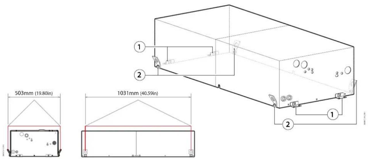
- remove the unit from the pallet only using the brackets on the structure as lifting points. Always use all four lifting brackets (pos. 2 in Fig. 3.a) to lift the unit, according to the diagram below. It is forbidden to lift the unit by hand; residual risk of the unit falling during installation if an improper hoisting device/accessory is used;
- when lifting, keep the unit horizontally with the covers closed and secured. Residual risk of the unit falling during installation if it is lifted without the covers;
- place the unit horizontally in its final position, avoiding knocks and making sure not to deform/damage the refrigerant and water connections;
- firmly secure the unit using screws through the "L" sections (position 1 in Fig. 3.a) on the structure. It is forbidden to make the refrigerant, water or electrical connections without first having secured the unit in its final position. Note there is residual risk of the unit falling if installed at a height and accessed using unsuitable equipment.

Caution: the Heosbox base does not bear its own weight with the covers open and not fixed to the frame. Make sure that the box is placed on a flat surface or on an equivalent support system before opening the covers.
text_image
503mm (19.80in) 1031mm (40.59in)Fig. 3.a
4. INSTALLATION
The unit is installed and commissioned as described below; please see the Carel "Heos" manual (+0300078EN) for details on programming.

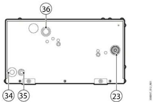
Notice: the water and refrigerant connections are located on the site side to the electrical connections (Fig.4.a):
text_image
36 34 35 23Fig. 4.a
Ref. Description
| 23 Water inlet connection: |
| 1" NPT threaded male (NAM vers.) |
| 36 Water outlet connection: |
| 1" NPT threaded male (NAM vers.) |
| 34 Refrigerant inlet connection (*) |
| 35 Refrigerant outlet connection (*) |
Tab. 4.a
(*) Notice: the water and refrigerant connections are located on the opposite side to the electrical connections, as shown in the figure: the refrigerant connections are made using pipe couplings whose diameter and thickness varies according to the size of the unit, see "Refrigerant connections".
4.1 Water connections
Refer to Figure 4.a.

Caution: before continuing, make sure the unit is powered off, and disconnect switch QS1 and the switch or disconnect device on the box power supply line in the OFF position (see the wiring diagram).
The mains power disconnect device must have a contact opening distance that allows complete disconnection in overvoltage category III conditions; It must also be incorporated into the Heosbox power supply line in accordance with national regulations.
To simplify installation and maintenance:
- install a manual shut-off valve immediately before the water inlet to the unit (the valve is not supplied by CAREL);
• install automatic air vent valves (not supplied by CAREL) in the piping, at the highest positions in the circuit; - avoid piping layouts in which water may stagnate when the system is stopped;
- fit appropriately-sized expansion vessels to avoid water hammer from damaging the system;
- install mechanical and/or magnetic filters to minimise the presence of impurities in the circuit.

Caution: the water connections must always be completed by ied personnel who have the qualifications and authorizations ried by local regulations, using appropriate personal protective ment (PPE), who are aware of the necessary precautions and who are to correctly and safely complete all required operations.

Caution: the SP and ST values for the water circuit connected to the box refer to the lowest SP or ST of all the components in the circuit.
The unit's water connections have 1" NPT for NAM versions; the unit should be connected to the water loop without any reductions in diameter, as such reductions may affect the unit's performance or cause malfunctions. The water circuit must be thoroughly cleaned of any processing residues (shavings, dust, etc.) before being connected to the unit. It is recommended to install an inspectable "Y" filter at the inlet to each condenser to ensure adequate protection. It is recommended to use a filter with the same diameter as the piping (1") and with a filtration capacity of at least 400 μm or finer. Regular maintenance must be performed on the inspectable filter so as to ensure correct operation of all the units connected to the water loop. The diameter of the water loop piping and the pressure head at the inlet to each individual Heosbox unit must be sized so as to ensure a water flow-rate at the condenser inlet in compliance with the nominal flow-rate stated in this document under "Technical Specifications".
All of the units have been designed to give a water-side pressure drop of about 30 kPa, so as to simplify installation in a loop with multiple units connected in parallel. By maintaining a pressure drop of 30 kPa between the condenser inlet and outlet on each unit, the water flow-rate to the condenser is certain to be approximately equal to the value required for correct operation of the unit, as declared in the "Technical Specifications". The installer is responsible for the correct construction and balancing of the water circuit. Carel Industries S.p.A. declines all liability for water loop installations that do not comply with the aforementioned instructions and in such cases does not guarantee correct operation of the unit.
4.2 Supply water specifications
The HEOS box units are designed to work with mains water mixed with ethylene glycol (antifreeze additive), with a concentration in proportion to the total volume of the water loop equal to:
- Nominal*: 20%;
- Minimum: 10%;
• Maximum: 50%.

Notice: (*) reference percentage for unit performance shown in the
"Technical Specifications".
Use of antifreeze additive:
- is a necessary precaution if the water loop is served by a dry cooler and the outside temperature drops below 0°C.
• is mandatory for systems that use chillers to cool the water loop. - is good practice to prevent corrosion and ensure constant water circuit performance over time.
- inhibited propylene glycol with a minimum concentration of 10% and a maximum of 52% by volume can be used. As propylene and ethylene glycol have different thermal properties, performance of the Heosbox unit may differ from the values shown in the "Technical Specifications".

Caution: read the safety and technical data sheet for the antifreeze
additive before handling the fluid and adding it to the water circuit.
4.3 Refrigerant connections
Refer to Figure 4.a.

Caution: before continuing, make sure the unit is powered off,
placing disconnect switch QS1 and the switch or disconnect device on the Heosbox power supply line in the OFF position (see the wiring diagram).
The mains power disconnect device must have a contact opening distance that allows complete disconnection in overvoltage category III conditions; it must also be incorporated into the Heosbox power supply line in accordance with national regulations. The refrigerant connections supplied are stubs of bare copper pipes with variable diameter and thickness, depending on the size of the unit. It is good practice to use copper pipes of the same type and with the same diameter as those coming out of the unit, avoiding differences in diameter of more than one size.
Part number Refrigerant inlet piping Refrigerant outlet piping
| [-] | Outside diam. Thickness Outside diam. Thickness | ||||||||
| [mm] | [in] | [mm] | [in] | [mm] | [in] | [mm] | [in] | ||
| HB1US03M0W1A0 | 12 0.47 | 1 | 0.04 6 | 0.236 | 0.75 | 0.03 | |||
| HB1US03E0W1A0 | 12 0.47 | 1 | 0.04 6 | 0.236 | 0.75 | 0.03 | |||
| HB1USL0D0W1A0 | 12 0.47 | 1 | 0.04 6 | 0.236 | 0.75 | 0.03 | |||
| HB1US04M0W1A0 | 12 0.47 | 1 | 0.04 6 | 0.236 | 0.75 | 0.03 | |||
| HB1US04E0W1A0 | 12 0.47 | 1 | 0.04 6 | 0.236 | 0.75 | 0.03 | |||
| HB1USL1D0W1A0 | 12 0.47 | 1 | 0.04 6 | 0.236 | 0.75 | 0.03 | |||
| HB1US06M0W1A0 | 15 0.59 | 1 | 0.04 10 | 0.394 | 0.75 | 0.03 | |||
| HB1US06E0W1A0 | 15 0.59 | 1 | 0.04 10 | 0.394 | 0.75 | 0.03 | |||
| HB1US02D0W1A0 | 15 0.59 | 1 | 0.04 10 | 0.394 | 0.75 | 0.03 | |||
| HB1US08M0W1B0 | 18 0.71 | 1 | 0.04 10 | 0.394 | 0.75 | 0.03 | |||
| HB1US08E0W1B0 | 18 0.71 | 1 | 0.04 10 | 0.394 | 0.75 | 0.03 | |||
| HB1US03D0W1B0 | 18 0.71 | 1 | 0.04 10 | 0.394 | 0.75 | 0.03 | |||
| HB1US08M3W1B0 | 18 0.71 | 1 | 0.04 10 | 0.394 | 0.75 | 0.03 | |||
| HB1US08E3W1B0 | 18 0.71 | 1 | 0.04 10 | 0.394 | 0.75 | 0.03 | |||
| HB1US02D3W1B0 | 18 0.71 | 1 | 0.04 10 | 0.394 | 0.75 | 0.03 | |||
Tab. 4.b
The unit must be connected to the evaporator section via refrigerant piping in a workmanlike manner, by qualified operators using brazing. The piping must be securely fixed and not transmit vibrations to the Heosbox unit.
Connection procedure
- Wear all personal protective equipment needed to complete the connection procedure: gloves, protective glasses and safety shoes.
- Make sure the unit is powered off, placing disconnect switch QS1 and the switch or disconnect device on the Heosbox power supply line in the OFF position (see the wiring diagram).
- Make sure that the unit is firmly anchored to the system it is part of, using all of the "L" brackets at the base of the structure.
- Open the refrigerant circuit cover panel.
- With the valves closed, connect Heosbox to the unit's refrigerant circuit; before opening the valves, check the pressure in the circuit, which must be around 1 bar; open the valves slowly and then carry out leak testing, empty the circuit and charge with refrigerant.
- Expel the inert gas (nitrogen) from inside the unit. Use the pressure ports (pos. 39, 40 and 48) arranged on the suction side, on the discharge side and on the liquid line. Take care to avoid any danger of materials and/or fluids being expelled outside of the unit.
- Fully open the liquid injection valve (pos. 24) and, where present, the expansion valve (pos. 26, single evaporator unit only). The unit is already supplied with the electronic expansion valves fully open; to check the position use the CAREL manual actuator, P/N E2VMAG0000.
- Remove the two plugs on the refrigerant inlet and outlet pipes.
- Cover the structure with a metal screen so as to not damage the paint.
- Cover the refrigerant shut-off valves with a wet rag (pos. 31 and 32) to avoid overheating that would damage them.
- Connect the two refrigerant pipes, inlet (pos. 34) and outlet (position 35) to the rest of the refrigerant circuit by braze welding.
- Open the two shut-off valves located near the refrigerant inlet and outlet pipes (pos. 31 - 32).
- After brazing the refrigerant circuit, charge the circuit with nitrogen to a maximum pressure of 20 barg (290 psi) and check that there are no leaks by measuring the pressure with a pressure gauge or other suitable instruments.
The Heosbox unit cannot be connected to the evaporating system using any other type of connection from that specified, otherwise the warranty will be void.


qualified personnel who have the qualifications and authorizations required by local regulations, using appropriate personal protective equipment (PPE), who are aware of the necessary precautions and who are able to correctly and safely complete all required operations.
Residual risk of expulsion of pressurized fluids/bursting of equipment if the instructions regarding the maximum pressure limits in the low pressure circuit are not observed when checking for leaks with nitrogen following welding on site.
4.4 Electrical connections

Caution: before continuing, make sure the unit is powered off, ing disconnect switch QS1 and the switch or disconnect device on the box power supply line in the OFF position (see the wiring diagram).
The mains power disconnect device must have a contact opening distance that allows complete disconnection in overvoltage category III conditions; it must also be incorporated into the Heosbox power supply line in accordance with national regulations. It is compulsory to follow the instructions on the wiring diagrams and comply with the minimum sizes of the multi-core cables shown in the table below before connecting the devices managed by the electrical panels.
| Part number | Power supply 208V | 1 ph Defrost 208 V | Light 24 V | Evap. Fan 24 V | Rail heater 24 V | Defrost 24 V |
| [-] | ||||||
| HB1US****W1A0 | 4XAWG 6 | AWG 12 | AWG 18 | AWG 18 | AWG 18 | AWG 18 |
| HB1US****W1B0 | 4XAWG 6 | AWG 12 | AWG 18 | AWG 18 | AWG 18 | AWG 18 |
Tab. 4.c
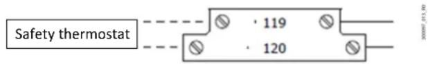
If a defrost heater is connected to the dedicated connector, the safety thermostat output must also be managed; see the panel wiring diagrams. This acts as thermal protection for the heaters used by the installer.
If the safety thermostat is not fitted, as the showcase heater features external protection against overtemperature, use the red wire (AWG18) to electrically connect terminals 119 and 120 on the electrical panel.
text_image
Safety thermostat 119 120Fig. 4.b

Caution: the electrical connections must always be completed by ied personnel who have the qualifications and authorizations ed by local regulations, using appropriate personal protective ment (PPE), who are aware of the necessary precautions and who are to correctly and safely complete all required operations.
4.5 Kit installation
The WiFi gateway is available as an optional kit for all Heosbox part numbers:
| Part number | WiFi gateway HBOPZGATX0000 |
| [-] | |
| HB1US****W1A0 | x |
| HB1US****W1B0 | x |
Tab. 4.d
For the electrical connection of the kit, see the information in the wiring diagrams and in this manual:
- before opening the electrical panel, move disconnect switch QS1 to OFF:
- when connecting the wires, make sure that the tip of the wire is fully inserted into the opening provided on the terminal;
- open the bag with the 2 screws;
- take the WiFi gateway and fix it to the holes provided on the external panel interface (housing the probe outputs), using the two screws provided together with the kit, in the space designated as "WIFI optional" on fig. 2.i;
- connect the RS485 gateway output with the terminal screen-printed "pLAN" to the external interface of the box (housing the probe outputs);
- run the Gateway power cable through the cable gland marked GATEWAY and connect it to the gateway power supply;
- take the black wire on the extension numbered 35 and fix it to the terminal XA1:102;
- take the black wire on the extension numbered 36 and fix it to the terminal XA1:101;
- close the electrical compartment and move the disconnect switch to ON to restart the unit.
4.6 Refrigerant charging procedure
Use only R448A or R449A certified refrigerant to charge the Heosbox unit. The following points should be considered general indications for correctly charging refrigerant into the unit, and are not technical specifications. The expansion valves must be correctly sized in order to complete the charging operation successfully. CAREL Industries S.p.A. may in this case, based on specific agreements, act as a consultant for the design/installation/commissioning/use of the unit, however in no case does it accept liability for the correct operation of the unit and the overall system if the warnings or suggestions provided in this manual or in other product technical documents are not heeded. In order to charge the unit (as described in the steps listed below), switch on and read the controller's display, so as to monitor some operating variables that are useful in the refrigerant charge process (such as superheat). To read and use the Carel "Heos" controller, see the manual (+0300078EN).
The recommended sequence is as follows:
-
Electrically disconnect Heos Box using the on/off switch on the unit and the disconnect device upstream of the unit's power supply line. Then remove the refrigerant circuit cover panel.
-
Make sure that all of the valves (24), (26), (31), (32) in Fig. 2.e are completely open.
-
Using a vacuum pump, bring the system to a pressure of less than 0.25 mbars (187 mHG), medium vacuum. The time the circuit is kept in a vacuum must be evaluated on site, according to the volume of the circuit and in any case must not be less than 60 minutes.
-
Prepare a system to weight the amount of refrigerant charged into the unit, and write the value on the rating label affixed in this document and to the Heosbox structure.
-
Charge the unit with a refrigerant pre-charge (e.g. 2 kg (4.4 lbs)) in order to activate the control system and switch on the compressor.
-
Check that the valve stators (24), (26) (see Fig. 2.e) are correctly installed.
-
Power on Heos Box using the on/off switch on the unit and the disconnect device upstream of the unit's power supply line.
-
Set the Heosbox unit to OFF (screen Aa01 on the controller).
-
Adjust the condensing temperature to the lowest possible value (lowest possible water inlet temperature with nominal flow) (screen M04 on the controller).
-
Set the Heosbox unit to ON (screen AA01 on the controller) and make sure that the compressor is close to maximum speed, at the same time making sure that the unit works within the operating range stated under "Transport and operating conditions" above (main screen M01, and screens M04 and M08 on the controller).
-
Make sure that the compressor remains running at the maximum allowed speed for a few minutes (air control temperature close to the set point; for a Multi-Evaporator configuration, the air control temperature must be close to the set point on each unit) (main screen M01 on the controller)
-
If the superheat is greater than the set point (SH > SHset) and the expansion valve/valves are fully open (EEV%=100%), add refrigerant (e.g. 100/200 g) (for a Multi-Evaporator configuration, the superheat on each evaporator must be monitored as described here) (screen M08 on the controller. To check the superheat set point, see the Carel Heos manual, as described previously)
-
Wait a few minutes to let the system stabilize.
-
Repeat steps 12 and 13 until SH=SHset and EEV%<90% (for multi evaporator configurations this must be checked on each unit)
-
Check the refrigerant temperature in the section of piping leaving the condenser and make sure that subcooling is between 0 and 5K (0<SBC<5K) (screen M05 on the controller)
-
Carefully check for leaks using suitable instruments, after having performed the refrigerant charge.
If the system is in good working order, no bubbles are evident in the flow indicator (33) on the unit. Always make sure that the colour of the sensitive ring inside the moisture indicator (33) is actually green (no moisture present).
Low condensing temperature and high compressor speed are set so as to obtain the highest refrigerant flow and the lowest possible pressure differential across the expansion valve/valves. The valve's capacity to control superheat in these conditions will guarantee correct control even in other normal unit operating conditions.
Caution: the refrigerant charge must always be completed by qualified personnel who have the qualifications and authorizations required by local regulations, who are aware of the necessary precautions, using appropriate personal protective equipment (PPE), and who are able to correctly and safely complete all required operations.
Residual risk of pressurized parts yielding if the installer does not follow the refrigerant gas charge instructions.
4.7 Refrigerant recovery procedure
The following points should be considered general indications for correctly recovering refrigerant from the unit, and are not technical specifications. The recommended sequence is as follows:
Switch Heos Box off.
-
Electrically disconnect Heos Box using the on/off switch on the unit and the disconnect device upstream of the unit's power supply line. Then remove the refrigerant circuit cover panel.
-
Maintain the flow of water and glycol at the condenser inlet.
-
Make sure the refrigerant inlet/outlet valves on the unit are closed.
-
Check the position of the stators on the electronic expansion valves (if present in the box) and liquid injection valves respectively. Disconnect the stators on the valves and open the valves using a suitable magnet in the kit supplied by Carel (P/N E2VMAG0000).
-
Retrieve the refrigerant contained in the circuit through the ports on in the liquid, suction and discharge lines. Weigh the amount of refrigerant retrieved so to subsequently recharge the unit with the same amount of refrigerant.
In the event of brazing or cutting operations on the refrigerant circuit (e.g. to replace a component), it is recommended to completely discharge all of the R448A or R449A refrigerant contained in the Heosbox unit.
4.8 Commissioning checklist
For correct installation and commissioning of the unit, the recommended steps are as follows:
-
Make sure that the "Water Connections" have been carried out as described in paragraph 4.1.
-
Make sure that the "Refrigerant Connections" have been carried out as described in paragraph 4.3.
-
Make sure that the "Electrical Connections" have been carried out as described in paragraph 4.4.
-
Make sure that there is at least one display kit available (PGD terminal, P/N PGDEH00FZ0)
-
Make sure that the condenser cooling system (water loop) is correctly installed and operational.
-
Make sure there is the correct water flow through the water connections on the unit;
-
Connect the PGD terminal to position 13 in Fig. 2.h, or Fig. 2.g (for NAM versions).
-
If connecting a PLD terminal, make sure that dipswitch 1 on the controller is in the ON position (default), as described in the Carel Heos manual (±0300078EN). For Multi-Evaporator systems, each controller can have its own PLD terminal.
-
For Multi-Evaporator configurations only:
a.: Check correct connection of the stators on all expansion valves (Main and Secondary), as shown in paragraph 6, on the Multi-Evaporator units. b.: Check correct connection of the RS485 serial line between the Main and Secondary controllers.
-
Only when using a multi-evaporator system, make sure that: a: Each secondary unit has the correct address set in the pLAN network (controller screen Ea03). This setting must be done with the pLAN RS485 serial between the units disconnected. When finished, reconnect it b.: The number of evaporators is set on the Main unit (contr. screen Eb03) c.: On each Main and Secondary unit in the same multi-evaporator network, make sure to set the capacity of the evaporator that each controller refers to (screen Eb04).
-
Make sure that the amount of refrigerant charge complies with the specifications in paragraph 4.6.
-
Make sure the unit parameters have been set correctly, as shown in the instructions in the Carel Heos manual (+0300078EN).
-
If installing a supervisory system, see Chap. 7.
5. MAINTENANCE
Heosbox is a product that requires minimal maintenance. Always comply with the minimum clearances described in "DIMENSIONS AND WEIGHTS" so as to be able to carry out routine maintenance operations safely.
The only maintenance operations to be carried out are the following:
Monthly maintenance:
- visually inspect the outside of the box. Make sure there are no water spills or dripping due to condensation;
Quarterly maintenance:
- keep the area around the box clean and uncluttered, making sure there is sufficient air change and enough free space in front of the two ventilation grilles for air intake and exhaust (pos. 3 and 4);
- remove any built-up dust or debris from the two air grilles that may affect the flow of air inside the box;
- leakage of refrigerant and/or lubricant fluid (stains or drops on the piping, on the piping insulation or the structure);
• water spills or dripping due to condensation; - build-up of dust or debris inside the electrical panel and/or refrigeration compartment;
- traces of moisture dissolved in the refrigerant, by observing the colour of the liquid/moisture indicator (pos. 33) installed in the refrigeration compartment;
- clean and, if appropriate, replace the water filter installed in the water line outside of the unit.
Six-monthly maintenance:
- visually inspect the inside of the box. It is forbidden to remove the outer protection panels without first disconnecting the unit from the power supply, moving disconnect switch QS1 to OFF (see the wiring diagram). Temporarily remove the protective panels on the refrigeration compartment and the electrical panel, and make sure the following are absent.

Notice: in any case, based on the observed conditions, evaluate the to extend or reduce the frequency of maintenance operations.
Maintenance operations other than those described that involve the removal/replacement/repair of one or more components inside the unit or in any case any work that involves wiring/assembly/disassembly of additional components/accessories that involve any unauthorized modifications to the unit or parts of it, are not considered routine maintenance and, unless any non-conformities had been identified by CAREL Industries S.p.A., automatically void the warranty.

Caution: the maintenance operations must always be completed by iied personnel who have the qualifications and authorizations ried by local regulations, who are aware of the necessary precautions, appropriate personal protective equipment (PPE), and who are able rrectly and safely complete all required operations.
5.1 Spare parts list
REFRIGERATION UNIT
| Ref. Fig. 2.f and 2.g Description Version | ||
| 16 Compressor All | ||
| 19 Filter-drier All | ||
| 31 Ball valve at refrigerant inlet All | ||
| 32 Ball valve at refrigerant outlet All | ||
| 30 Check valve All | ||
| 27 High pressure switch | All | |
| 38 Capillary tube All | ||
| 22 Plate heat exchanger-condenser | All | |
| 37 Oil separator | All | |
| 18 Liquid receiver | All | |
| 15 Discharge temperature probe | All | |
| 20 Liquid temperature probe | All | |
| 21 Water inlet temperature probe | All | |
| 28 Water outlet temperature probe | All | |
| 29 Suction temperature probe | All | |
| 17 Suction pressure transducer | All | |
| 25 Discharge pressure transducer | All | |
| 26 Electronic expansion valve | All | |
| 24 Liquid injection valve | All | |
| 33 Liquid/moisture indicator | All | |
| - | E2V unipolar stator with 2 m cable | All |
| - | Needle valve for pressure ports | All |
| 49 | Safety valve | NAM only |
Tab. 5.a
ELECTRICAL SECTION
| Ref. Fig. 2.h and 2.i | Description Version | |
| 14 Rear door disconnect switch, 3P 80A | All | |
| 14 Black lever for disconnect switch | All | |
| - | Heos electronic board | All |
| 46 PSD2 inverter | All | |
| - | IP67 cable for pressure probes | All |
| - | Light relay | All |
| - | Fan relay | All |
| - | SSR | All |
| 52 Transformer | NAM only | |
| - | Telephone connector L=0.8 m | All |
| - | Showcase air intake probe | All |
| - | Showcase air outlet probe All | |
| - | Defrost probe | All |
Tab. 5.b
Table des matières
1. AVERTISSEMENTS 5
DÉCLARATIONS DE CONFORMITÉ
flowchart
graph TD
    A["Supervisor network"] --> B["Main/Secondary multi evaporator network"]
    B --> C["BMS"]
    A --> D["Control panel with sensor"]
    B --> E["Control panel with sensors"]
    C --> F["Computer with keyboard"]
Fig. 2.b
text_image
wall Min. 150mm (5.91 in) wallFig. 2.a
Vue supérieure
text_image
wall Min. 300mm (11,81 in) Min. 150mm (5,91 in) wallFig. 2.b

Remarque:
text_image
Technical diagram of an industrial machine with numbered components for identificationFig. 2.c
text_image
Technical diagram of an electronic device interior with numbered components and labeled connectors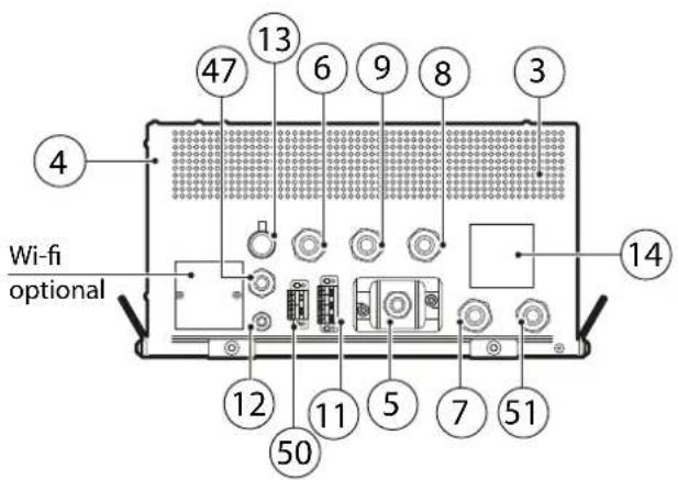
text_image
4 13 6 9 8 3 47 6 14 12 11 5 7 51 50 Wi-fi optionalFig. 2.d
Ref. Description
text_image
503mm (19.80in) 1031mm (40.59in)Fig. 3.a
4. INSTALLATION
text_image
Diagram of a device layout with numbered components and circular elements, likely for assembly or labeling.Fig. 4.a
Réf. Description
Important: Do not remove this copy of the unit label from the manual. The customer is required to carefully keep all of the documentation supplied with the unit for any future maintenance or service.