
Heosone - Uncategorized Carel - Free user manual and instructions
Find the device manual for free Heosone Carel in PDF.


| Product Type | Intelligent electronic control system for refrigerated cabinets |
| Application | Closed glass door cabinets (300-600 l) and open curtain cabinets (up to 0.8 m²) |
| Controller Dimensions (IP00) | 194 x 220 x 85 mm (7.6 x 8.7 x 3.3 in) |
| Power Supply Voltage | 115-127 V~ or 220-240 V~ (depending on model) |
| Power Supply Frequency | 50/60 Hz |
| Rated Input Current (115V Small) | 5.2 A (min) to 4.7 A (max at 115 V) |
| Compressor Type | BLDC rotary hermetic compressor (e.g., FC-E040, FC-E057, FC-E100) |
| Refrigerant Compatibility | R290 (propane) and others according to IEC 60079-15 |
| Electronic Expansion Valve | CAREL E2V unipolar valve, controlled directly by controller |
| User Interface Display | 3-digit red/white LED display with icons, 4-button keypad |
| Communication Interfaces | NFC (Android only), Bluetooth Low Energy, RS485 (Modbus/Carel) |
| Operating Temperature Range (Controller) | -20 to 45 °C (-4 to 113 °F) |
| Storage Temperature Range (Controller) | -40 to 60 °C (-40 to 140 °F) |
| Ingress Protection | IP00, IP20, or IP44 (depending on version) |
| Safety Features | Safety Torque Off (STO) input, overcurrent, overtemperature, short-circuit protection |
| HACCP Compliance | Yes, with Type HA and HF alarms |
| Software Tools | CAREL Applica app (mobile), Applica Desktop, SPARK (OEM configuration) |
| Certifications | CE, UL, RoHS, EMC according to EN 61000 series |
| Warranty | 2 years on materials (from production date) |
| Recommended Cleaning | Soft cloth with neutral detergent or water (front user terminal) |
Frequently Asked Questions - Heosone Carel
User questions about Heosone Carel
0 question about this device. Answer the ones you know or ask your own.
Ask a new question about this device
Download the instructions for your Uncategorized in PDF format for free! Find your manual Heosone - Carel and take your electronic device back in hand. On this page are published all the documents necessary for the use of your device. Heosone by Carel.
USER MANUAL Heosone Carel
High-efficiency solution for propane plug-in units

USER MANUAL


GENERAL WARNINGS

CAREL bases the development of its products on decades of experience in HVAC, on continuous investments in technological innovations to products, procedures and strict quality processes with in-circuit and functional testing on 100% of its products, and on the most innovative production technology available on the market. CAREL and its subsidiaries/affiliates nonetheless cannot guarantee that all the aspects of the product and the software included with the product respond to the requirements of the final application, despite the product being developed according to start-of-the-art techniques. The customer (manufacturer, developer or installer of the final equipment) accepts all liability and risk relating to the configuration of the product in order to reach the expected results in relation to the specific final installation and/or equipment. CAREL may, based on specific agreements, act as a consultant for the successful commissioning of the final unit/application, however in no case does it accept liability for the correct operation of the final equipment/system. The CAREL product is a state-of-the-art product, whose operation is specified in the technical documentation supplied with the product or can be downloaded, even prior to purchase, from the website www.carel.com. Each CAREL product, in relation to its advanced level of technology, requires setup/configuration/programming/commissioning to be able to operate in the best possible way for the specific application. Failure to complete such operations, which are required/indicated in the user manual, may cause the final product to malfunction; CAREL accepts no liability in such cases. Only qualified personnel may install or carry out technical service on the product. The customer must only use the product in the manner described in the documentation relating to the product. In addition to observing any further warnings described in this manual, the following warnings must be heeded for all CAREL products:
- prevent the electronic circuits from getting wet. Rain, humidity and all types of liquids or condensate contain corrosive minerals that may damage the electronic circuits. any case, the product should be used or stored in environments that comply with the temperature and humidity limits specified in the manual;
- do not install the device in particularly hot environments. Too high temperatures may reduce the life of electronic devices, damage them and deform or melt the plastic parts. In any case, the product should be used or stored in environments that comply with the temperature and humidity limits specified in the manual;
- do not attempt to open the device in any way other than described in the manual;
- do not drop, hit or shake the device, as the internal circuits and mechanisms may be irreparably damaged;
- do not use corrosive chemicals, solvents or aggressive detergents to clean the device;
- do not use the product for applications other than those specified in the technical manual.
All of the above suggestions likewise apply to the controllers, serial cards, programming keys or any other accessory in the CAREL product portfolio. CAREL adopts a policy of continual development. Consequently, CAREL reserves the right to make changes and improvements to any product described in this document without prior warning. The technical specifications shown in the manual may be changed without prior warning. The liability of CAREL in relation to its products is specified in the CAREL general contract conditions, available on the website www.carel.com and/or by specific agreements with customers; specifically, to the extent where allowed by applicable legislation, in no case will CAREL, its employees or subsidiaries/affiliates be liable for any lost earnings or sales, losses of data and information, costs of replacement goods or services, damage to things or people, downtime or any direct, indirect, incidental, actual, punitive, exemplary, special or consequential damage of any kind whatsoever, whether contractual, extra-contractual or due to negligence, or any other liabilities deriving from the installation, use or impossibility to use the product, even if CAREL or its subsidiaries/affiliates are warned of the possibility of such damage.
DISPOSAL

Fig. 1
Fig. 2
INFORMATION FOR USERS ON THE CORRECT HANDLING OF WASTE ELECTRICAL AND ELECTRONIC EQUIPMENT (WEEE)
The product is made up of metal parts and plastic parts. In reference to European Union directive 2002/96/EC issued on 27 January 2003 and related national legislation, please note that:
- WEEE cannot be disposed of as municipal waste and such waste must be collected and disposed of separately;
- the public or private waste collection systems defined by local legislation must be used. In addition, the equipment can be returned to the distributor at the end of its working life when buying new equipment;
- the equipment may contain hazardous substances: the improper use or incorrect disposal of such may have negative effects on human health and on the environment;
- the symbol (crossed-out wheeled bin) shown on the product or on the packaging and on the technical leaflet indicates that the equipment has been introduced onto the market after 13 August 2005 and that it must be disposed of separately;
- in the event of illegal disposal of electrical and electronic waste, the penalties are specified by local waste disposal legislation.
Warranty on materials: 2 years (from production date, excluding consumables).
Approval: the quality and safety of CAREL S.p.A. products are guaranteed by the ISO 9001 certified design and production system.

READ CAREFULLY IN THE TEXT!
Separate as much as possible the probe and digital input cables from cables to inductive loads and power cables, so as to avoid possible electromagnetic disturbance. Never run power cables (including the electrical panel cables) and signal cables in the same conduits.
Key to the symbols:
Caution: to bring critical issues to the attention of those using the product.
Notice: to focus attention on important topics; in particular the practical application of the various product functions.
Dangerous voltage
Caution, hot surface.
Caution: this product is to be integrated and/or incorporated into the final apparatus or equipment. Verification of conformity to the laws and technical standards in force in the country where the final apparatus or equipment will be operated is the manufacturer's responsibility. Before delivering the product, Carel has already completed the checks and tests required by the relevant European directives and harmonised standards, using a typical test setup, which however cannot be considered as representing all possible conditions of the final installation.
Index
1. Warnings....7
1.1 General warnings 7
1.2 Fundamental safety rules ....7
2. Introduction 8
2.1 Components 8
3. Installation 12
3.1 Heosone system 12
3.2 Controller....13
3.3 User terminal 21
3.4 Compressor 23
3.5 E2V unipolar valve 25
3.6 Pressure probe (SPKT00**P0) 27
3.7 Temperature probes 28
3.8 General connection diagram 29
4. User interface....30
4.1 Introduction 30
5. Menu description 33
5.1 Menu tree 33
6. Checks before commissioning 33
7. Commissioning....34
7.1 User terminal 34
7.2 Mobile device 35
7.3 Computer 36
8. Functions....38
8.1 Inputs and outputs 38
8.2 Control 45
8.3 Defrost 50
8.4 Evaporator fans 56
8.5 Condenser fans 58
8.6 Anti-sweat heater or fan modulation 60
8.7 Electronic valve 62
8.8 Compressor 67
8.9 Generic functions 69
9. Parameter table 72
9.1 Parameter table 72
10. Alarms and signals....80
10.1 Signals 80
10.2 Types of alarms....80
10.3 Display alarm log 81
10.4 Alarm table 81
10.5 Alarm parameters 83
10.6 HACCP alarms 85
1. WARNINGS
1.1 General warnings
- The Heosone system must be incorporated by professionally qualified personnel into a complete unit or system as part of a fixed installation and, in any case, inside a metal enclosure.
- This device contains dangerous voltages. Failure to observe the instructions contained in this user manual may cause serious damage to people and things.
- The Heosone system and components comply with the requirements of standard IEC 6007915, ed.4, as required by EN 60335-2-34:2011, EN 60335-2-40/A1: 2007 and EN 60335-2-89: 2011 for the use of hydrocarbons as refrigerants (R290 – propane).
- The components of the Heosone system are to be used in systems with R290 refrigerant, however applying appropriate solutions to prevent the risk of explosion at any time (safe zone).
- The components of the Heosone system are not ATEX certified and cannot for any reason be used in areas with explosive or flammable atmospheres; the owner, designer and installer are responsible for ensuring strict compliance with the standards in force in order to avoid all risks.
- Follow the recommendations in this user manual when installing system components, so as to ensure correct operation and maximise refrigerator performance.
- Design of the Heosone system, installation, commissioning and maintenance of the Heosone system are all operations reserved for qualified personnel, who have understood all of the safety, installation, operation and maintenance warnings contained in this user manual +0300052EN, downloadable, even prior to purchase, from www.carel.com, under "Documentation".
1.2 Fundamental safety rules
• Before carrying out any maintenance work:
disconnect the Heosone system and the system components from the power supply by moving the main system switch to "off"; wait at least 5 minutes;
always check, using a suitable multimeter, that there is no dangerous voltage across the terminals;
always make sure that the compressor has stopped completely. Freely rotating motors may generate dangerous voltages across the terminals on the Heosone system, even when this is not powered.
check that the heat sink is not too hot: contact with the heat sink may cause serious burns.
When Heosone is connected to the power supply, the compressor terminals U, V and W are live, even if the motor is not running.
Never measure insulation resistance or dielectric strength with alternating current, as this may cause faults on some of the internal components; the Heosone system is supplied factory-tested for the applied voltage; during final testing when assembled on the unit, it can therefore be disconnected, or alternatively the test can be performed using direct current, as specified by the standards.
There may be dangerous control voltage at the relay outputs even when Heosone is not connected to the mains power supply.
The level of safety provided by the enabling inputs (excluding the "safety torque off" input when used in compliance with the standards) on Heosone is not sufficient in critical applications without adopting additional independent measures to ensure safety. For all applications in which malfunctioning may cause serious damage to people and things, the risks must be assessed and additional protection measures adopted.
Ensure a correct earth connection and only use cables specified by local regulations in force. The Heosone system typically has leakage current less than 1 mA.
Ensure compliance with all national and local laws and regulations regarding the safety of low voltage equipment installations, as well as the requirements for correct use of tools and personal protective equipment.
Only use the system components for the purposes specified by the manufacturer. Do not modify or replace the components unless recommended by the manufacturer, as this may cause fire, electric shock or other damage.
2. INTRODUCTION
Heosone is an intelligent and connected electronic control system for refrigerated cabinets:
- closed, with glass door, medium capacity (300 to 600 l);
- open, with curtain, small (up to 0.8 m ^2 open area).
It controls the compressor and the electronic expansion valve. The controller is part of the Heosone system, which includes the CAREL E2V electronic expansion valve, CAREL BLDC rotary compressor, user terminal, a specific software tool (for configuration, profiling, categorisation, parameter setting and commissioning), and an App for communication with mobile devices via NFC (Near Field Communication) or Bluetooth Low Energy (BLE). Heosone ensures low power consumption and high efficiency on the final product, in accordance with the requirements of European directives and market trends.
Main functions and features
Overview:
- integrated solution with single controller that manages compressor control and operation;
- flexible mounting: vertical or horizontal so as to best exploit the space available;
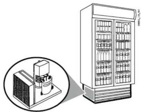
- compact dimensions for assembly at the bottom of the bottle cooler;
- wide ambient temperature operating range (from -20 to 45°C);
• can be installed in residential and industrial environments; - simple and quick configuration thanks to the dedicated CAREL "Applica" app using NFC or Bluetooth technology;
- quick programming for OEM and service thanks to specific software tools
- safety torque off digital input for unit protection;
• electrical connections available using a variety of connectors, with retaining catches integrated into the plastic cover;
• high switching frequency to limit compressor noise; - easy troubleshooting/diagnostics on control status by reading numerous variables;
- protection functions for the controller (short-circuit, overcurrent, overtemperature), compressor (overtemperature, current limitation, phase loss, locked rotor) and system (safety torque off input).

Fig. 2.a
natural_image
Illustration of a refrigerator with a close-up inset showing internal components (no text or symbols)2.1 Components
Control
The following part numbers are currently available:
Part number Technical code Description
| HZROGC2A0006* | APC06A2FDA14001 | HEOSONE SMALL 115V 2DCFAN FULL 16/8/5A E040 IP44 |
| HZROHC2A0007* | APC07B2FDA14001 | HEOSONE SMALL 230V 2DCFAN FULL 16/8/5A E040 IP44 |
| HZROICOB0008* | APC08C0FD810001 | HEOSONE MEDIUM 230V NO DCFAN FULL 16/8/5A E057/E100 IP00 |
| HZROIC2B0009* | APC09C2FD810001 | HEOSONE MEDIUM 230V 2DCFAN FULL 16/8/5A E057/E100 IP00 |
| HZROJCOB0010* | APC10C0FD814001 | HEOSONE MEDIUM 230V NO DCFAN FULL 16/8/5A E057/E100 IP44 |
| HZROJC2B0011* | APC11C2FD814001 | HEOSONE MEDIUM 230V 2DCFAN FULL 16/8/5A E057/E100 IP44 |
Tab. 2.a
Notice: *: 0 = single pack; 1 = multiple pack of 5 pcs
The technical code is used for certification (e.g. in the UL file).

natural_image
Exterior view of a black industrial machine with three parallel plates (no visible text or symbols)Fig. 2.b
Each drive is identified by a series of thirteen alphanumeric characters and each position has a precise meaning.
Notice: For part numbers not included in Table 2.a, contact Carel HQ
| drive part number HZ R0 J 10 A 0 005 0 | |||||||
| position 1-2 3-4 5 6-7 8 9 10-12 | 13 |
Tab. 2.b
The meaning of each position is:
Pos. Meaning Options Description
| 1-2 family code | HZ | |||
| 3-4 reserved | R0 | |||
| 5 | power, IPxx rating | E | Small, 115Vac, IP00 | |
| F | Small, 230Vac, IP00 | |||
| G | Small, 115Vac, IP44 | |||
| H | Small, 230Vac, IP44 | |||
| I | Medium, 230Vac, IP00 | |||
| J | Medium, 230Vac, IP44 | |||
| 6-7 input/output options | 10 | BASIC I/O, 16 A relay | ||
| 20 | BASIC I/O, 16/8 A relay | |||
| 30 | BASIC I/O, 16/8/5 A relay | |||
| 12 | BASIC I/O, 16 A relay, 2x fan control | |||
| 22 | BASIC I/O, 16/8 A relay, 2x fan control | |||
| 32 | BASIC I/O, 16/8/5 A relay, 2x fan control | |||
| A0 | FULL I/O, 16 A relay | |||
| B0 | FULL I/O, 16/8 A relay | |||
| C0 | FULL I/O, 16/8/5 A relay | |||
| A2 | FULL I/O, 16 A relay, 2x fan control | |||
| B2 | FULL I/O, 16/8 A relay, 2x fan control | |||
| C2 | FULL I/O, 16/8/5 A relay, 2x fan control | |||
| 8 | compatible compressor | A | E040 series compressor | |
| B | E057/E100 series compressor | |||
| 9 | accessories | 0 | no options available | |
| 10-12 | reserved | |||
| 13 | packaging | 0 | single pack | |
| 1 | multiple pack | |||
Tab. 2.c
Applica
The "Applica" app can be used to configure the controller from a mobile device (smartphone, tablet), via NFC (Near Field Communication) or Bluetooth Low Energy (BLE). Users can both configure the commissioning parameters and set groups of preset parameters according to specific needs (configurations).

Fig. 2.c
Configuration and commissioning software
- SPARK: PC software created for manufacturers of HVAC/R units to customise units during the design phase. This is the tool used by manufacturers (OEMs) who need to have control over access and content available to service personnel working in the field using Applica and Applica Desktop. Connection to the controller is via an RS485 serial cable.
- Applica desktop: PC software corresponding to the Applica app, designed to meet the same commissioning and maintenance requirements as the mobile version.
The software can be downloaded from ksa.carel.com. SPARK must be activated via a license, requested from Carel.
The configuration software (for manufacturers) can be used to:
- create new parameter categories (tags);
- create profiles with password-protected access to custom read and read/write parameter lists;
- tune the controller parameters;
- add languages and parameter descriptions.
The commissioning software (for service) can be used to:
- access the cooler with the assigned profile;
- create configurations;
- apply configurations;
• complete the commissioning procedure; - carry out troubleshooting.
Notice: the commissioning software can be used as an alternative to the Applica app.
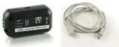
For the electrical connection, use the USB/RS485 converter CVSTDUMOR0.

flowchart
graph LR
    A["Commissioning tool"] --> B["CVSTDUMOR0"]
    B --> C["RS485"]
    C --> D["HMI"]
    B --> E["T+"]
    B --> F["T-"]
    B --> G["GND"]
    B --> H["Shield"]
    C --> I["T/R/GND"]
    C --> J["BMS"]
    C --> K["19"]
    style A fill:#f9f,stroke:#333
    style B fill:#ccf,stroke:#333
    style C fill:#cfc,stroke:#333
    style D fill:#fcc,stroke:#333
    style E fill:#ffc,stroke:#333
    style F fill:#ffc,stroke:#333
    style G fill:#ffc,stroke:#333
    style H fill:#ffc,stroke:#333
    style I fill:#fcc,stroke:#333
    style J fill:#fcc,stroke:#333
    style K fill:#fcc,stroke:#333
Fig. 2.d
User terminal (technical leaflet +050002915)
The user terminal includes the display and keypad, comprising four buttons that, when pressed alone or combined with other buttons, access the operations available for the "User" and "Service" profiles. The integrated NFC or Bluetooth interface allows interaction with mobile devices and simplifies unit commissioning (after having installed the CAREL "Applica" app for the Android operating system, see chap. Commissioning).

natural_image
Three digital temperature displays with red LED indicators and a coiled cable (no visible text or symbols)Fig. 2.e
| Part number | Type |
| AX4000PS1002(*) | Heosone user interface, RS485, 4 buttons, buzzer, red display, NFC |
| AX4000PS2003(*) | Heosone user interface, RS485, 4 buttons, buzzer, white display, NFC+BLE |
| ACS00CB000020 | User interface cable, 1.5 m |
| ACS00CB000010 | User interface cable, 3 m |
| ACS00CB000022 | User interface cable, 1.5 m, multiple pack (10 pieces) |
| ACS00CB000012 | User interface cable, 3 m, multiple pack (10 pieces) |
Tab. 2.d
(*): 0 = single pack; 1 = multiple pack of 20 pcs
Notice: NFC connectivity is only compatible with the Applica app for the Android operating system.
Cable and connector kit
The controllers are not supplied with connectors; these need to be ordered separately
Part number Description
| ACS00CK002000 | Heosone connector kit, no STO |
| ACS00CK002001 | Heosone connector kit, no STO, multiple pack of 10 pcs |
| ACS00CB000230 | Kit of 10 one-metre cables for Micro-fit connectors |
| ACS00CB000330 | Kit of 8 one-metre cables for Micro-fit connectors |
| ACS00CB000140 | Compressor-controller connection cable L=0.6m |
| ACS00CB000540 | STO-controller connection cable L=0.6m |
Part number Description
| Compressor cables | |
| AC500CB000140 | Compressor-controller connection cable L=0.6m |
| AC500CB000540 | STO-controller connection cable L=0.6m |
Tab. 2.e
Compressor (P/N ZCBQFC\*\*\*V0\*\*, manual +030222170 available on ksa.carel.com)
Compact rotary hermetic compressor with high-efficiency brushless DC motor.
This operates at variable speed so as to easily adapt to the load, thus ensuring rapid cooling and precise temperature control.

natural_image
Black industrial electrical component with mounting base (no visible text or symbols)Fig. 2.f
| Part number Description Notes | |
| ZCBQFC040V020 BLDC COMPRESSOR QINGAN FC-E040Y6T2 200V Metallic cover | |
| ZCBQFC040V021 BLDC COMPRESSOR QINGAN FC-E040Y6T2 200V Metallic cover pallet of 75 pcs | |
| ZCBQFC057V020 BLDC COMPRESSOR QINGAN FC-E057Y6T2 200V Metallic cover | |
| ZCBQFC057V021 BLDC COMPRESSOR QINGAN FC-E057Y6T2 200V Metallic cover pallet of 75 pcs | |
| ZCBQFC100V020 BLDC COMPRESSOR QINGAN FC-E100Y6T2 200V LT Metallic cover | |
| ZCBQFC100V021 BLDC COMPRESSOR QINGAN FC-E100Y6T2 200V LT Metallic cover pallet of 75 pcs |
Tab. 2.f
Unipolar valve kit (P/N HZE01\*\*\*\*\*)
To simplify the supply, valve kits have been created containing both the valve and the stator and the corresponding pressure probes with cable and superheat temperature probe in a single package.
The following part numbers are currently available:
| Part number Description | |
| HZE01F032F310 HEOSONE | E2V KIT-E2V03FSAC0+E2VSTA0320+NTC030HF01+SPKC002310+SPKT0043P0 |
| HZE01F052F310 HEOSONE | E2V KIT-E2V05FSAC0+E2VSTA0320+NTC030HF01+SPKC002310+SPKT0043P0 |
| HZE01F092F310 HEOSONE | E2V KIT-E2V09FSAC0+E2VSTA0320+NTC030HF01+SPKC002310+SPKT0043P0 |
| HZE01F032F320 HEOSONE | E2V KIT-E2V03FSAC0+E2VSTA0320+NTC030HF01+SPKC002310+SPKT0013P0 |
| HZE01F052F320 HEOSONE | E2V KIT-E2V05FSAC0+E2VSTA0320+NTC030HF01+SPKC002310+SPKT0013P0 |
| HZE01F092F320 HEOSONE | E2V KIT-E2V09FSAC0+E2VSTA0320+NTC030HF01+SPKC002310+SPKT0013P0 |
| HZE01F032F3A0 HEOSONE | E2V KIT-E2V03FSAC0+E2VSTA0320+NTC030HF01+SPKC002310+SPKT0033P0+SPKT0043P0 |
| HZE01F052F3A0 HEOSONE | E2V KIT-E2V05FSAC0+E2VSTA0320+NTC030HF01+SPKC002310+SPKT0033P0+SPKT0043P0 |
| HZE01F092F3A0 HEOSONE | E2V KIT-E2V09FSAC0+E2VSTA0320+NTC030HF01+SPKC002310+SPKT0033P0+SPKT0043P0 |
Tab. 2.g
In particular, the valves are the E2V**F*** model, while the stator is the unipolar version complete with 2 m cable; for further details see the technical leaflet +050001680.

natural_image
Product photo of four different industrial sensors or connectors with black cables and metallic fittings (no visible text or symbols)Fig. 2.g
Notice: for the characteristics of these components, see paragraphs 3.5*, 3.6*, 3.7*.
For guidelines on installing the sensors on the unit, see manual +040010025.
USB/RS485 converter (P/N CVSTDUMOR0 technical leaflet +050000590)
Electronic device used to interface an RS485 network to a personal computer via the USB port.
natural_image
Two electronic devices: a black battery and a white cord with metallic connectors (no visible text or symbols)Fig. 2.h
3. INSTALLATION
3.1 Heosone system
3.1.1 Functional diagrams
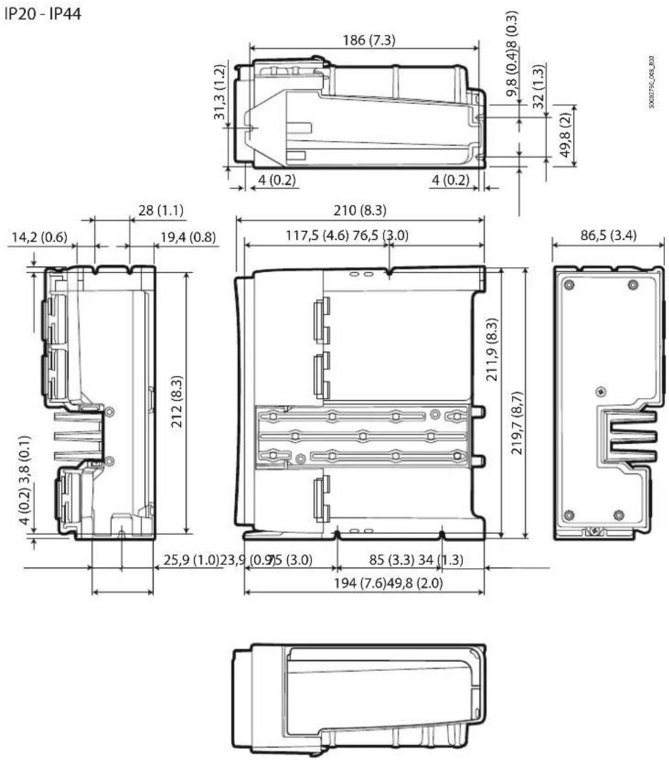
Notice: the main warnings are shown below, however for a complete and detailed description of the electrical and mechanical characteristics, see the technical leaflet +050002740.
The recommended component layout guarantees correct ventilation of the controller and effective temperature control in the refrigerated cabinet.

flowchart
graph TD
    A["Heosone"] --> B["Heater"]
    B --> C["Heater Inlet"]
    C --> D["Heater Outlet"]
    D --> E["Heater Filter"]
    E --> F["Heater Inlet"]
    F --> G["Heater Outlet"]
    G --> H["Heater Filter"]
    H --> I["Heater Inlet"]
    I --> J["Heater Outlet"]
    J --> K["Heater Filter"]
    K --> L["Heater Inlet"]
    L --> M["Heater Outlet"]
    M --> N["Heater Filter"]
    N --> O["Heater Inlet"]
    O --> P["Heater Outlet"]
    P --> Q["Heater Filter"]
    Q --> R["Heater Inlet"]
    R --> S["Heater Outlet"]
    S --> T["Heater Filter"]
    T --> U["Heater Inlet"]
    U --> V["Heater Outlet"]
    V --> W["Heater Filter"]
Fig. 3.a
Key
| S1 | Intake probe (ref. A) |
| Outlet probe (ref. B) | |
| S2 | Defrost probe |
| S3 | Suction temperature probe |
| S4 | Evaporation pressure probe |
| CP | Compressor |
| L | Liquid receiver |
| F | Filter |
| S | Liquid sightglass |
| E2V | Electronic expansion valve |
| E | Forced-air evaporator |
| C | Air-cooled condenser |
Tab. 3.a
3.1.2 Warnings
It is recommended to:
- place the controller in the intended position to ensure proper ventilation and heat dissipation;
- install the electronic expansion valve immediately after the condenser to minimise pipe length and refrigerant charge;
- maximise condenser efficiency to reduce refrigerant charge;
• properly insulate the piping leaving the electronic expansion valve and entering the evaporator to prevent condensation; - properly insulate and maintain an adequate distance between the condenser outlet and inlet so as to avoid affecting thermodynamic performance.
Notice:
- use a liquid receiver to optimise performance;
- install a liquid separator at the evaporator outlet to prevent liquid hammer in the compressor piping.
3.2 Controller
3.2.1 Warnings
Caution: avoid installing the controller in environments with the following characteristics:
• relative humidity greater than 90% or with condensation;
• strong vibrations or knocks;
- exposure to aggressive and polluting atmospheres (e.g.: sulphur and ammonia gases, saline mist, smoke) which may cause corrosion and/or oxidation;
• strong magnetic and/or radio frequency interference (thus avoid installation near transmitting antennae);
- exposure to direct sunlight and the elements in general.
3.2.2 Dimensions - mm(in)
IP00


natural_image
Technical line drawing of a rectangular electronic component with mounting holes (no text or symbols)Fig. 3.b
50002790_008_R02
Fig. 3.c
3.2.3 Drilling template and assembly
The controller can be mounted by fixing screws ( 4 mm) for vertical (ref. A) or horizontal (ref. B) assembly.
Vertical long side Vertical short side Horizontal short side
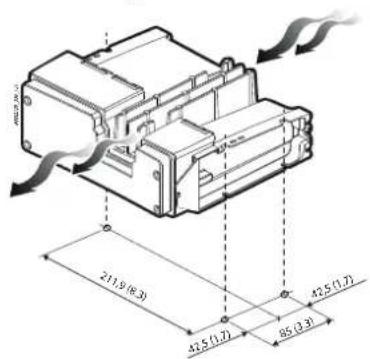


Fig. 3.d Fig. 3.e Fig. 3.f
3.2.4 Cooling
Sufficient air flow (at least 2m/s) and air change must be provided inside the compartment where the system is placed (made up of fan, compressor and control). The air flow must hit the control from the opposite side to the electrical connection terminals, to cool the heatsink and compressor. A support has been inserted for housing a 40 mm side fan near the heatsink. The maximum ambient temperature is 45 °C.

natural_image
Diagram of a refrigeration unit with cooling fan and air transfer system (no text or symbols)Fig. 3.g
Caution:
- ensure the minimum required air flow of 2 m/s across the heat sink, as specified in the table of technical specifications;
- avoid shielding the air flow due to the installation of other components.
3.2.5 Electrical installation
Caution:
- before carrying out any maintenance, disconnect the controller from the power supply by moving the main system switch to "off". Once having powered down the controller, wait at least 5 minutes before disconnecting the electrical cables;
- always make sure that the compressor has stopped completely. Freely rotating motors may generate dangerous voltages across the terminals on Heosone, even when this is not powered;
- the controller does not feature protection against short-circuits to earth; suitable devices must be used to detect faults upstream of the circuit.
Description of the terminals

Fig. 3.h
| Ref. | Connector | Description | |
| 1 | J1 | L, N | Single phase power supply (see the Technical specifications) |
| Earth (*) | |||
| 2 | Earth (*) | ||
| U, V, W | Compressor output | ||
| 3 | J3 (***) | Evaporator fan | |
| 4 | J4 (**) | Condenser fan | |
| J3 / J4 881 2 3 4 5 6 7200TM (200W) | 1 | Vdc | |
| 2 | Reserved | ||
| 3 | Reserved | ||
| 4 | GND | ||
| 5 | Vdc | ||
| 6 | VSP - set point output | ||
| 7 | FG - tachometer input | ||
| 5 | J5 | Reserved | |
| 6 | J6 | Safety digital input (safety torque off (***) ) | |
| 7 | J7 | Fieldbus | |
| 8 | J8 HMI | User terminal connector | |
| Ref. Connector Description | |||
| 9 J9 BMS connector | |||
10 J10 (#)  | ID3 Digital input 3: not used | ||
| ID5 Digital input 5: not used | |||
| +V Power supply to 4-20 mA active probes | |||
| S6 Universal probe input (optional) | |||
| VL Not used | |||
| ID4 Digital input 4: not used | |||
| GND Common reference for probes, digital inputs | |||
| S4 Evaporation pressure probe | |||
11 J11  | +5VREF 5 V: power to ratiometric probes | ||
| S3 Suction temperature probe | |||
| S1 Outlet temperature probe | |||
| Y1 (***) 0-10 V control for evaporator fan | |||
| ID1 Digital input 1: door switch | |||
| GND Common reference for probes, digital inputs | |||
| S5 Universal probe input (optional) | |||
| S2 Defrost probe | |||
| Y2 (***) 0-10 V control for condenser fan | |||
| ID2 Digital input 2: not used | |||
| 12 J12 C1/2 Common for relays 1, 2 | |||
| NO1 | Digital output (relay) 1 | ||
| NO2 | Digital output (relay) 2 | ||
| 13 J13 C3 | Common for relay 3 | ||
| NO3 | Digital output (relay) 3 | ||
| 14 J14 | E2V valve connector | ||
(#) On models where featured.
(*) The earth connections inside the controller are electrically connected together and to PE.
(**) J3/J4: terminals for Vdc modulating evaporator/condenser fan respectively, driven directly by the controller.
(***) Voltage-free digital input. If not used, short-circuit using the jumper supplied in the connector kit.
(****) Y1/Y2: outputs for controlling the externally-powered Vac modulating evaporator/condenser fans respectively.
Tab. 3.b
Caution:
- observe the requirements of the Low Voltage and Electromagnetic Compatibility directives for sizing the protection devices upstream of the controller and correct earthing;
- in the European Union, all units that incorporate the controller must comply with the Machinery Directive 2006/42/EC. Specifically, the manufacturer of the unit is responsible for installing a main switch and conformity to standard EN 60204-1;
- for a fixed installation in accordance with IEC 61800-5-1, a device is required that interrupts the circuit between the power supply and the controller;
- only use hard-wired power connections; the controller must be earthed: the earth wire must be sized for the maximum fault current.
- insertion and removal of connectors must be take place when the control is not powered.
3.2.6 Conformity to EMC standards
Heosone has been designed in compliance with the requirements of European EMC standards. All models are fitted with an internal filter that reduces conducted emissions to the power supply line. It is the installer's responsibility to ensure that the device or system that Heosone is incorporated into is compliant with the standards in force in the country in which it is used. Conformity to EMC standards requires compliance with the instructions shown under "Electrical connections" and, as this also depends on the layout of the wiring, needs to be verified on the final equipment, as required by the relevant product standard. As regards the general EMC guidelines, strictly observe the instructions shown under "Electrical connections".
3.2.7 Electrical connections
For installation proceed as described below, with reference to the general connection diagram (see the following paragraph). Each terminal on Heosone can be connected to different models of connectors, with retaining catches integrated into the plastic cover. The complete list of connectors is available in the chapter "Technical specifications".
Caution:
- separate as much as possible the probe and digital input cables from cables to inductive loads and power cables, so as to avoid possible electromagnetic disturbance. Never run power cables (including the electrical panel cables) and probe signal cables in the same conduits;
- the cables must be sized as described in table of Technical specifications;
- do not install the cables connected to the controller terminal block in the immediate vicinity of power devices (contactors, circuit breakers, etc.). Reduce the path of cables as much as possible, and avoid spiral paths that enclose power devices.
- the power supply earth must be connected directly to the controller, without branches to other devices; the cross-section of the earth wire must be greater than or equal to the cross-section of the phase wires; earth impedance must be compliant with national and local regulations.
Power supply
Use cables rated for temperatures up to 105^ C. Use suitable terminals for the connectors and cables used. Insert the connectors into the housings provided and fix them in place using the retaining catches. Then lightly tug the cables to check correct tightness.

Fig. 3.i
The controller must be earthed: the spade terminal provided can be used for this purpose. To minimise EMC problems it is recommended to use a power cable that includes an earth wire, connected to the terminal ⏻.
The power supply earth must be connected directly to the earth bar in the electrical panel, without branches to other devices:
- the size of the earth wire must be greater than or equal to the size of the phase wires;
• the earth impedance must comply with national and local regulations; - in compliance with UL regulations, safety earth connections must be made using an eyelet terminal.
Connect the power wires to terminals L1 and N; for the cross-sections of the wires and the type of circuit breaker (MCB), see "Technical specifications".

Caution: do not connect power to terminals U, V, W.
Compressor
To ensure conformity to the EMC directive it may be necessary to use a ferrite and/or a shielded cable with foil + braid. The cable can also be installed in steel and copper conduits. In this case, it is recommended to install the ferrite core (for example Fair-Rite 2631102002) around the U, V, W wires and excluding the earth wire, located between the shield earth and the connector. The shield is fully earthed via a metal clamp at both ends of the cable, as close as possible to the controller's terminals. In the event where the shield is connected to the earth spade on the controller (not recommended), the connection should be made by twisting the shield. The twisted section must be as short as possible, and the length must not exceed five times the width. Earth the compressor via its metal casing.
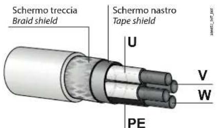
Fig. 3.j
Compressor electrical connections
See document +030222170 available on ksa.carel.com and the Heosone system manual +0300099EN.

Caution:
• do not reverse the compressor phases;
- do not install a circuit breaker between the drive and the compressor.
Fans
Heosone can control direct current (DC) or alternating current (AC) fans. DC fans are powered directly by the controller.
Caution: outputs J3 and J4 are designed to deliver a maximum total power, as specified in the technical data table; in the event of higher power output for an extended time, the controller may be damaged. It is therefore necessary to make sure that the connected DC fans have a lower total power input in all operating conditions (see the table of technical specifications).
Bottle cooler
All the unit's metal components must be adequately connected to the PE. Metal parts must be coupled together via adjoining, unpainted points of contact, to ensure good electrical continuity. It is recommended to install the controller inside the condensing unit and to shield the entire unit. Any wiring leaving the shielded section must be suitably shielded, for example using shielded cables or metal conduits. In some cases, the use of ferrites on the wires leaving the shielded section may be sufficient.

natural_image
Technical line drawing of an industrial machine inside a container, showing internal components and airflow paths (no text or symbols)Fig. 3.k
Leakage current
The drive is designed to produce minimum leakage current, nonetheless leakage current depends on the length and type of motor cable, the motor, the effective switching frequency, the type of earth connection used and the type of RFI filter installed, and therefore may exceed 1 mA.
Compressor protection - safety digital input
Connect the two safe torque off digital safety input terminals to the normally-closed voltage-free contact of a safety device, such as a maximum pressure switch (safety device, see the connection diagram). When the contact is open, drive operation is interrupted. If the Safe Torque Off feature is not used, the two safety digital input terminals must be short-circuited to enable correct operation of the controller.
Serial network connection
For the serial connection use a shielded, twisted cable for RS485 networks. For very long networks, add a 14 W 120 resistor between the Tx/Rx- and Tx/Rx+ terminals on the last controller or device connected, to avoid possible communication problems. To ensure conformity to the EMC directive it may be necessary to use a ferrite core (for example, Fair-Rite 2631540002) fitted immediately before the drive terminal, winding the three wires (excluding the cable shield) around this.

Fig. 3.1
3.2.8 Technical specifications
| Model 115 Vac vers. - Small 230 Vac vers. - Small 230 Vac vers. - Medium | |||||
| Physical specifications | Dimensions - IP00 version: 194 x 220 x 85 mm;IP20 version: 202 x 220 x 89 mm;IP44 version: 202 x 220 x 89 mm | ||||
| Assembly horizontal or vertical with screws | |||||
| Material technopolymer | |||||
| Heat dissipation: max power (W) 65 50 90 | |||||
| Min air flow m/s 2 | 2 | 2 | |||
| m3/h | 13 13 13 | ||||
| Flammability | Casing GW1: 850 °C (V2 in accordance with UL94) | ||||
| Ball pressure test temperature | 125 °C | ||||
| Colour | Grey RAL 7016 | ||||
| Ingress protection (IP) | multiple versions available: IP00; IP20; IP44 | ||||
| Environmental conditions | Storage temperature | -40T60 °C | |||
| Operating temperature | -20T45 °C | ||||
| Humidity | < 90 % RH non condensing | ||||
| Altitude | Up to 2000 m asl; above 1000 m requires downgrading of maximum output current: 1%/100 m | ||||
| Rated power supply | 115 - 127 V ~ | 220 - 240 V ~ | 220 - 240 V ~ | ||
| Input frequency | 50/60 Hz | ||||
| Rated current draw* (A)*: Referred respectively to minimum and maximum input voltage | 5.2 - 4.7 | 2.7 - 2.5 | 5.2 - 4.7 | ||
| Min power consumption (W) | 5 | 5 | 5 | ||
| Terminal block | plug-in male-female or "edge" connectors.wire sizes: see the connector table | ||||
| Clock | standard, precision: ± 50 ppm; date/time retention after shutdown: 72 h | ||||
| Software class and structure | Control functions: A;Safety management: B to EN/UL 60730 and R.1 to EN/UL 60335-1 | ||||
| Pollution degree | 3 | ||||
| Class of protection against electric shock | |||||
| Type of action | 1C (relay), 2Y (compressor protection) | ||||
| Rated impulse voltage | 4 kV | ||||
| Surge immunity category | Installation class (EN 61000-4/5): 4 | ||||
| Compressor output | Output voltage | 0 to Input voltage | |||
| Output frequency | 0 to 500 Hz | ||||
| Output current (A) | 2.5 | 1.3 | 2.5 | ||
| Overload capacity | 115% of rated output current for 40 s | ||||
| Maximum cable length | 3 m | ||||
| Switching frequency | 6 kHz | ||||
| Frequency resolution | 0.1 Hz | ||||
| Protection functions | Controller | Short-circuit, overcurrent, overvoltage and undervoltage, overtemperature | |||
| Compressor | Overtemperature, current limitation, phase loss, locked rotor.For the reset characteristics, see the alarm table. | ||||
| System | Safety Torque OFF input | ||||
| Analogue inputs (Lmax=10 m) | S1, S2, S3: NTC | Resolution 0.1 °C; 10 kΩ @ 25 °C, Beta 3435, error: ±1 °C in the range -50T50°C, ±3 °C in the range 50T90°C; | |||
| S4, S5: ratiometric pressure probe (0.5-4.5 V) | Resolution: 0.1% fs; measurement error: 2% max; 1% typical | ||||
| S6: universal probe: ratiometric (0.5 4.5 V), electronic (4-20 mA), 0-10 V input, NTC, NTC-HT, PT1000 | NTC: Resolution 0.1 °C; 10 kΩ @ 25 °C, Beta 3435, error: ±1 °C in the range -50T50°C, ±3 °C in the range 50T90°C;NTC-HT: 50 kΩ @ 25 °C, Beta 25/85 3977 ± 1%, error: ±1.5 °C in the range -20T115°C, 4 °C in the range outside of 20T115 °C;Ratiometric (0-5 V); Resolution: 0.1% fs; measurement error: 2% max; 1% typicalElectronic (4-20 mA); error 5% fs, typical 1%; 0-10 V error 2% fs, typical 1%.PT1000: resolution 0.1 °C, 1 kΩ @ 0 °C; error ± 2 °C in the range -60T120 °C. | ||||
| Digital inputs (Lmax=10 m) | ID1, ID2, ID3, ID4, ID5 | Voltage-free contact, not optically-isolated, typical closing current 6 mA, voltage with contact open 13 V, max contact resistance 50 Ω | |||
| T STO safety digital input: safety torque off | Reinforced insulation from power supply;Voltage-free contact, voltage with contact open: 13 V typical;Closing current: 20 mA typical | ||||
| DC fan outputs 1/2 | J3, J4 | PIN 1 | Vdc: 310-360Vdc, MAX 140 mA | ||
| PIN 2 | Reserved | ||||
| PIN 3 | Reserved | ||||
| PIN 4 | GND | ||||
| PIN 5 | Vdc: 15 Vdc, max 50 mA | ||||
| PIN 6 | VSP: 0 to 8 Vdc (set point output) | ||||
| PIN 7 | FG: 0 to 8 Vdc (tachometer input) | ||||
| CAUTION: outputs J3 and J4 are designed to deliver a maximum total power of 60 W. Higher power will cause permanent damage to the controller. | |||||
| Analogue outputs (Lmax = 10 m) | Y1, Y2 | 0 to 10 V; 10 mA max PWM 100 Hz; max amplitude 10 V; 10 mA max | |||
| Valve output (Lmax=2 m, 6 m w. shielded cable) | J14 | CAREL E2V single-pole valve power supply: 13Vdc ± 10 %, min winding resistance 36Ω | |||
| Digital outputs (Lmax=10 m) | J12 | NO1 (*): 16 A, SPST relay, approval: EN 60730: 15 A, 250 V, 100000 cycles; UL60730: 10 FLA, 60 LRA, 250 Vac, 30000 cycles, Pilot duty B300, 6000 cyclesNO2 (*): 8 A, SPST relay, approval: EN 60730: 5(4), 250Vac, 100000 cycles; UL 60730: 10 A resistive, 250 Vac, 100000 cycles; 2 FLA, 12 LRA, 250 Vac, 30000 cycles | |||
| (*) The sum of currents on common terminal C1/2 for NO1 and NO2 must not exceed 15 A max. | |||||
| Probe power supply (Lmax=10 m) | J13 | NO3: SA, SPST relay, approval: EN 60730:4(1), 230Vac, 100000 cycles; UL 60730: 5 A resistive, 250 Vac, 30000 cycles; 1 FLA, 6 LRA, 250 Vac, 30000 cycles; Pilot Duty C300, 250 Vac, 30000 cycles | |||
| +5 VREF 5Vdc ± 2% to power the 0 to 5V | ratiometric probes.Max current delivered: 35 mA protected against short-circuits. | ||||
| +V | 8-11 V to power the 4-20 mA current probes.Max current delivered: 80 mA protected against short-circuits | ||||
| +VL | Not used | ||||
Model 115 Vac vers. - Small 230 Vac vers. - Small 230 Vac vers. - Medium
| Remote term. J8 | 13 Vdc ±10% to power the HMI terminal, RS485 serial communication | |
| BMS serial J9 Lmax = 500 m, shielded cable • Integrated | Protocol: Modbus/CarelHW driver: asynchronous half duplex RS485 SlaveNot optically-isolated3-pin plug-in connector, 3.81 mm pitchMax data rate: 115200 bits/s | |
| FieldBus serial Lmax = 500 m, shielded cable • Integrated | HW driver: asynchronous half duplex RS485 main. Typical reception resistance 96 kΩ, equal to 1/8 of unit load, i.e. 1/256 of maximum load applicable on the lineNot optically-isolatedMax data rate: 19200 bits/sMaximum number of connectable devices: 20Protocol: Modbus RTU | |
| Conformity to standards | CE conformity: | |
| Low voltage directive • 2014/35/EU | EN 60730-1, EN 60335-1 (sect. 29 & 30),EN 60335-2-34 (sect. 19.101 & 19.103),FCC & ETSI standards (for NFC in User Interface) | |
| Electromagnetic compatibility directive • | 2014/30/EUEN 61000-6-1/2/3/4EN 61800-3: Adjustable speed electrical power drive systems. EMC requirements, including specific test methodsEN61000-3-2: Electromagnetic compatibility (EMC). Part 3-2: Limits - Limits for harmonic current emissions (equipment input current <= 16 A per phase)EN 55014-1: Electromagnetic compatibility: Requirements for household appliances, electric tools and similar apparatus - Part 1: Emission | |
| Maximum permissible short-circuit current at the drive's terminals (IEC 61439-1) | 100 kA | |
| Minimum short-circuit current for tripping the fuses | 500 A | |
| Applications with flammable refrigerant gases | IEC 60079-15 (clauses 17 and 19, applied to relays according to type. However, acceptability of the relays must be verified and assessed in the final application). | |
| UL conformity | UL 60730-1, UL 60335-1, UL 60335-2-34, UL 60079-15 | |
| ROHS directive 2011/65/EN | EN 50581 | |
(*) The sum of currents on common terminal C1/2 for NO1 and NO2 must not exceed 15A max.
3.2.9 Connector table
| Ref. | Wiring terminals | Wire cross-section (mm2) | Lmax (m) |
| J1 | Spade: 6.3 mm female | 1.5 | - |
| ⊕ | Spade: 6.3 mm female | 1.5 | - |
| ⊕ | Spade: 6.3 mm female | 1.5 | - |
| J2 | Lumberg 3575 03 ..., MOLEX 91627-1502, TE 1-1740533-3 | 0.75 | 3 |
| J3 | JST XHP-7 | 0.3 | 3 |
| J4 | JST XHP-7 | 0.3 | 3 |
| J5 | Not used | - | - |
| J6 | Lumberg 3575 02 K10, Stocko 7262-002-004-960-000-00-G | ||
| J7 | Lumberg 3612 03 ..., Sauro CUF03001, Weco 130-P-020/3 | 0.13 | 10 |
| J8 | JST XHP-4 connector (user terminal side: JST ZHR-4 pin) +SXH-002T P0.6 (terminal) | 0.13 | 10 |
| J9 | Degson 15EDGK-3.81-03P-14-00A(H), Phoenix Contact MC 1.5/3-ST-3.81 | 0.081 to 1.31 | 500 |
| J10 | MOLEX Micro- FIT 43025- 0800, FCI Minitek 0430300004, FCI10127718-002PLF (terminal) 10127716-08LF (connector) + Molex | 0.05 to 0.52 | 10 |
| J11 | MOLEX Micro- FIT 43025- 1000, FCI Minitek 0430300004, FCI10127718-002PLF (terminal) 10127716-10LF (connector) + Molex | 0.05 to 0.52 | 10 |
| J12 | DEGSON 2EDGK-5.08-03P-14-13A(H)M3, PHOENIX CONTACT MSTB 2.5/3-ST-5.08, SAURO CIF03005 | 0.21 to 2.5 | 10 |
| J13 | DEGSON 2EDGK-5.08-02P-14-13A(H)M3, PHOENIX CONTACT MSTB 2.5/2-ST-5.08, SAURO CIF02005 | 0.21 to 2.5 | 10 |
| J14 | CAREL EXV unipolar valve connector | Pre-wired |
Tab. 3.d
3.2.10 Rated current values
The following table shows the rated input current and output current values, as well as the specifications for sizing the cables (cross-section, maximum length) and the fuses.
| Model | Rated input current | Protection fuses (*) | Protection fuses for USA - CAN (**) | Rated output current | Power cable sizes | Minimum comp. cable size | Maximum comp. cable length |
| (A) | (A) | (A) | (A) | (mm2) | (mm2) | (m) | |
| all versions115 Vac / Small | 3.8 | 16 | 15 | 1.3 | 1.5 | 0.75 | 3 |
| all versions230 Vac / Small | 2 | 16 | 15 | 1.3 | 1.5 | 0.75 | 3 |
| all versions230 Vac / Medium | 3.8 | 16 | 15 | 2.6 | 1.5 | 0.75 | 3 |
Tab. 3.e
^(1) type gG; ^(2) type CC
3.3 User terminal
3.3.1 Dimensions

Fig. 3.m
3.3.2 Installation
Preliminary operations
The user terminal is supplied with the frame already fitted. Nonetheless, this can be easily removed without affecting the IP protection rating.
Removing the frame
Press the frame gently upwards at point A until hearing a click and repeat the operation at the other points B, C, D so as to detach the frame.

Fig. 3.n
Panel mounting
Front:
- insert the cable from the electrical panel into point A (figure);
- run the cable through the cable gland H;
- Place the controller in the opening, press lightly on the side tabs and then on the front until fully inserted (the side tabs will bend, and the catches will attach the controller to the panel).

Fig. 3.0
Removal
Open the electrical panel and from the rear (figure):
- press on the mounting tabs and then push the controller out.

Fig. 3.p
3.8.1 Electrical connections
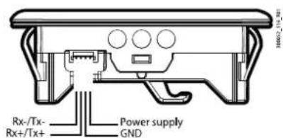
Fig. 3.q
3.3.3 Technical specifications
| Power supply 13 Vdc ± 10% obtained from Hcose | one controller; max. current 250 mA |
| Recommended power for connected controller: SELV or PELV | |
| Connector (integrated) JST 4-pin ZH P/N S4B-ZR- | SM4A-TF |
| Controller connection cable | Max length: 10 m. For lengths over 2 m and with the device not incorporated, use shielded cable.Size: AWG: 26Connectors:terminal side: JST ZH 4-pin; housing ZHR-4; terminal SZH-002T-P0.5controller side: user terminal JST XH 4-pin, housing XHP-4, terminal SXH-002T-P0.6 |
| Buzzer Available on all models | |
| Temperature sensor built-in | |
| Case Polycarbonate; dimensions: see the figures | |
| Mounting panel | |
| Display 3 digits, decimal point, and multi-function icons | |
| Operating temperature -20T60 °C | |
| Operating humidity < 90% RH non-condensing | |
| Storage temperature -35T70°C | |
| Storage humidity < 90% RH non-condensing | |
| NFC communication | Max distance 10 mm, variable according to the mobile device used |
| Ingress protection | IP65 front, IP20 rear |
| Environmental pollution | 3 |
| Ball pressure test temperature | 125°C |
| Rated impulse voltage | 0.8 kV |
| Type of action and disconnection | 1.Y |
| Control device construction Device to be incorporated | |
| Class of protection against electric shock | To be Incorporated in class I or II appliances |
| Serial interface | Modbus over RS485 |
| Software class and structure Class A | |
| Front cleaning | Use only a soft, non-abrasive cloth and neutral detergent or water |
| Certification | CE, ULElectrical safety: EN60335-1, UL60335-1, EN60730-1, UL60730-1Electromagnetic compatibility: EN61000-6, EN61000-3, EN55014-1, EN61000-4, FAC |
Tab. 3.f
3.4 Compressor
3.4.1 Structure
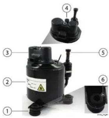
Fig. 3.r
Key:
| Ref. | Description |
| 1 | Vibration-isolation joint |
| 2 | Identification label |
| 3 | Cover |
| 4 | Discharge |
| 5 | Suction |
| 6 | PE (unpainted hole) |
3.4.2 Dimensions - mm

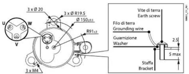
Notice: earth the compressor using an earth wire with eyelet connected to the pin with the unpainted hole (figure).
Code: ZCBQFC040V020: BLDC COMPRESSOR QINGAN FC-E040Y6T2 200V
| Cooling Capacity W | Evaporating temperature (°C) | |||||||
| -15 | -10 | -5 | 0 | 5 | ||||
| Condensing temperature (°C) | 65 | 446 | 552 | 675 | ||||
| 60 | 490 | 605 | 738 | |||||
| 55 | 426 | 533 | 657 | 800 | 965 | 1153 | 1367 | |
| 50 | 463 | 577 | 709 | 861 | 1036 | 1235 | 1461 | |
| 45 | 500 | 620 | 760 | 921 | 1105 | 1315 | 1552 | |
| 40 | 536 | 664 | 810 | 979 | 1172 | 1392 | 1641 | |
| 35 | 573 | 706 | 860 | 1036 | 1238 | 1467 | 1726 | |
| 30 | 610 | 748 | 908 | 1092 | 1301 | 1540 | 1809 | |
| 25 | 647 | 790 | 955 | 1145 | ||||
Tab. 3.g
Code: ZCBQFC057V020: BLDC COMPRESSOR QINGAN FC-E057Y6T2 200V
| Cooling Capacity W | Evaporating temperature (°C) | ||||||||||
| -35 | -30 | -25 | -20 | -15 | -10 | -5 | 0 | 5 | |||
| Condensing temperature (°C) | 65 | 682 | |||||||||
| 60 | 593 | 750 | 925 | ||||||||
| 55 | 386 | 512 | 652 | 809 | 988 | 1193 | 1428 | 1699 | |||
| 50 | 442 | 563 | 702 | 862 | 1048 | 1264 | 1514 | 1804 | |||
| 45 | 384 | 487 | 606 | 746 | 912 | 1107 | 1337 | 1605 | 1917 | ||
| 40 | 424 | 523 | 643 | 788 | 962 | 1170 | 1416 | 1705 | 2041 | ||
| 35 | 377 | 455 | 554 | 677 | 829 | 1015 | 1238 | 1504 | 1816 | 2179 | |
| 30 | 405 | 481 | 582 | 712 | 874 | 1074 | 1316 | 1603 | 1942 | 2335 | |
| 25 | 428 | 505 | 611 | 749 | 925 | 1142 | 1405 | 1717 | 2085 | ||
Tab. 3.h
Code: ZCBQFC100V020: BLDC COMPRESSOR QINGAN FC-E100Y6T2 200V
| Cooling capacity W | Evaporating temperature (°C) | ||||||||||
| -35 | -30 | -25 | -20 | -15 | -10 | -5 | 0 | 5 | |||
| Condensing temperature (°C) | 65 | 1049 | 1240 | ||||||||
| 60 | 1044 | 1251 | 1466 | ||||||||
| 55 | 734 | 924 | 1150 | 1417 | 1693 | 2008 | 2364 | 2798 | |||
| 50 | 804 | 1004 | 1242 | 1524 | 1857 | 2248 | 2703 | 3229 | |||
| 45 | 686 | 863 | 1073 | 1324 | 1621 | 1972 | 2382 | 2859 | 3410 | ||
| 40 | 730 | 915 | 1136 | 1399 | 1711 | 2080 | 2510 | 3010 | 3585 | ||
| 35 | 609 | 770 | 963 | 1194 | 1470 | 1798 | 2184 | 2635 | 3158 | 3758 | |
| 30 | 642 | 809 | 1010 | 1252 | 1541 | 1885 | 2289 | 2761 | 3306 | 3932 | |
| 25 | 677 | 850 | 1060 | 1313 | 1616 | 1975 | 2398 | 2890 | 3459 | ||
Tab. 3.i
Notice: condition: max speed (90rps), 11K SH, 8K subcooling.
Code: ZCBQFC040V020: BLDC COMPRESSOR QINGAN FC-E040Y6T2 200V
| Power W | Evaporating temperature (°C) | |||||||
| -15 | -10 | -5 | 0 | 5 | ||||
| Condensing temperature (°C) | 65 | 349 | 367 | 382 | ||||
| 60 | 329 | 344 | 356 | |||||
| 55 | 294 | 310 | 322 | 331 | 337 | 340 | 339 | |
| 50 | 278 | 291 | 300 | 307 | 311 | 311 | 308 | |
| 45 | 262 | 272 | 279 | 283 | 284 | 282 | 277 | |
| 40 | 246 | 254 | 259 | 260 | 259 | 254 | 247 | |
| 35 | 231 | 236 | 238 | 237 | 234 | 227 | 217 | |
| 30 | 216 | 218 | 218 | 215 | 208 | 199 | 187 | |
| 25 | 200 | 201 | 198 | 192 | ||||
Tab. 3.j
Code: ZCBQFC057V020: BLDC COMPRESSOR QINGAN FC-E057Y6T2 200V
| Power W | Evaporating temperature (°C) | ||||||||||
| -35 | -30 | -25 | -20 | -15 | -10 | -5 | 0 | 5 | |||
| Condensing temperature (°C) | 65 | 531 | 543 | 555 | 568 | 583 | |||||
| 60 | 478 | 491 | 503 | 515 | 528 | 541 | |||||
| 55 | 409 | 428 | 444 | 458 | 470 | 481 | 492 | 505 | |||
| 50 | 380 | 400 | 416 | 430 | 441 | 451 | 461 | 471 | |||
| 45 | 331 | 356 | 376 | 392 | 405 | 415 | 424 | 432 | 440 | ||
| 40 | 309 | 334 | 355 | 370 | 382 | 391 | 398 | 404 | 409 | ||
| 35 | 256 | 289 | 314 | 334 | 349 | 359 | 367 | 371 | 374 | 377 | |
| 30 | 236 | 269 | 294 | 313 | 326 | 335 | 340 | 343 | 343 | 341 | |
| 25 | 215 | 247 | 272 | 289 | 301 | 308 | 311 | 310 | 307 | ||
Tab. 3.k
Code: ZCBQFC100V020: BLDC COMPRESSOR QINGAN FC-E100Y6T2 200V
| Power W | Evaporating temperature (°C) | ||||||||||
| -35 | -30 | -25 | -20 | -15 | -10 | -5 | 0 | 5 | |||
| Condensing temperature (°C) | 65 | 766 | 10 | ||||||||
| 60 | 745 | 764 | 766 | ||||||||
| 55 | 610 | 660 | 705 | 746 | |||||||
| 50 | 587 | 631 | 671 | 705 | |||||||
| 45 | 523 | 565 | 603 | 638 | 666 | ||||||
| 40 | 504 | 541 | 574 | 603 | 626 | ||||||
| 35 | 443 | 479 | 512 | 541 | 564 | 582 | 592 | 593 | 584 | 563 | |
| 30 | 414 | 445 | 474 | 498 | 517 | 530 | 534 | 529 | 514 | 487 | |
| 25 | 372 | 400 | 424 | 445 | 459 | 467 | 466 | 455 | 434 | ||
Notice: condition: max speed (90rps), 11K SH, 8K subcooling.
3.4.3 Warnings
When installing the compressor, the following warnings must be observed:
- the compressor is charged with dry nitrogen at 0.05 - 0.08 MPa (gauge pressure); remove high pressure side (discharge tube side) rubber plug before application, otherwise refrigerant oil will flow out from the compressor;
• make sure that no foreign matter, such as solder, dust, etc.
• do not enter the refrigerant circuit from soldering/welding joints between compressor and piping, as well as between piping; - the compressor should not be operated to form a vacuum and to absorb air; emptying of the circuit should ensure that the vacuum is below 20 Pag;
• use the specified refrigerant for the compressor; - refrigerant should be charged from the end of the condenser into the circuit. Never charge refrigerant to the compressor directly;
- make sure that wiring is correct before starting the compressor. The duration between two start-ups must exceed three minutes. It is forbidden to run the compressor in the reverse direction and when empty;
- keep the system clean during assembly, the filter must be assembled in the refrigerant circuit to prevent blocking the capillary tube etc.
- do not reduce or increase the refrigerant oil during application as the compressor has been charged with the specified amount of oil;
- design the piping in order to ensure the oil inside the circuit returns to the compressor;
- to prevent liquid refrigerant accumulation in the compressor, ensure that the temperature at the bottom of compressor case is 5^ higher than the condensing temperature;
- the compressor can operate correctly at a maximum inclination of 5^ ;
- do not place the compressor horizontally or put it upside down. Do not drop the compressor. Do not put the compressor in the open air. Store the compressor inside rooms where the temperature is inside the range between -10 to +65°C;
- prevent water from entering the compressor. The compressor should not be left open in the atmosphere for more than 15 minutes. Power should not be applied to the hermetic terminals when the compressor is under vacuum. Temperature in the system during steady compressor operation should not be less than 35^ to prevent the wax in the oil from precipitating;
- wire according to compressor specifications (wiring diagram). Do not connect the compressor directly to the AC power supply. Incorrect wiring can cause reverse rotation and compressor faults.
The FC-E100 compressor combined with the Heosone Medium controller has an ideal sizing that takes advantage of the 50-90 rps range, with the following performance:
- MT application (-5/45°C): 1000-1200W nominal cooling, 1900W peak cooling, 400W average power, 675W peak power;
• LT application (-30/40°C): 350-450W nominal cooling, 750W peak cooling, 300W average power, 500W peak power.
Notice: operating continuously near the peak value may cause a decrease in the working life of the controller.
3.5 E2V unipolar valve
The E2V electronic valve is designed for installation in refrigerant circuits as a refrigerant expansion device, operating based on the superheat calculated by a pressure probe and a temperature probe installed at the evaporator outlet. The incoming fluid must be suitably subcooled to prevent the valve from operating with flash gas. Valve noise level may increase if refrigerant charge is insufficient or there is significant pressure drop upstream.
3.5.1 Dimensions

Fig. 3.t Tab. 3.m
| Valve type A | B | C | D | |
| E2V**FSA** copper 8-8mm IDM | 133.5mm(5.26inch) | 75.4 mm(2.97 inch) | 55.1 mm(2.17 inch) | 47.5 mm(1.87 inch) |
| E F G | ||||
| In. 6.5 / Out. 8 mm(In 0.26/Out 0.31 inch) | In. 6.5 / Out. 8 mm(In 0.26/Out 0.31 inch) | - | ||
3.5.2 Installation
See the technical leaflet for installation instructions.

Fig. 3.u

Fig. 3.v
3.5.3 Technical specifications (E2V\*\*FSAC\*)
| Compatibility Group 1: R1234yf, R290 | R600, R600aGroup 2: R22, R134a, R404A, R407C, R410A, R417A, R507A, R744, R1234ze, R448A, R449A, R450A, R513A |
| Maximum operating pressure (MOP): | CE approval: 60 bars (870psi). UL approval: 45 bars (652 psi) |
| Maximum operating pressure differential (MOPD): | 35 bars (508 psi); for E2V35 unipolar: 26 bars (377psi) |
| PED Gr 1 & 2, art. 4, par. 3. | When used with hydrocarbons, it meets the requirements of EN 60079-15: 2005-10, as required by EN 60335-2-40/A1:2006-04 and EN 60335-2-89:2002-12, EN 60335-2-89/A1:2005-04, EN 60335-2-89/A11:2004-07, EN 60335-2-89/A2:2007-03. The valves have been tested according to ATEX Directive 94/9/EC for Group 2, Category 3G refrigerants in accordance with harmonised standards EN 60079-15: 2005 (only the parts required by EN 60335-2-40 and EN 60335-2-89). |
| Refrigerant temperature -40T70 °C (-40T158 °F) | |
| Room temperature -30T70 °C (-22T158 °F) | |
| Contact CAREL for different operating conditions or alternative refrigerants. | |
Tab. 3.n
3.6 Pressure probe (SPKT00\*\*P0)
3.6.1 Dimensions/positioning
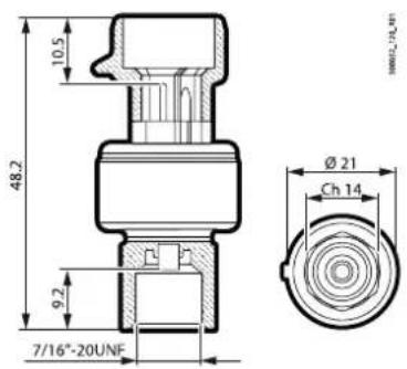
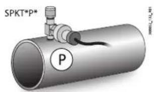
Fig. 3.w
Notice: the probe should be installed immediately downstream of the evaporator outlet, on the piping, so as to ensure accurate evaporation pressure measurement.
3.6.2 Electrical connections

| Power supply voltage (protected against reverse polarity and short-circuits) 5 Vdc ± 10% | |
| Output voltage 0.5-4.5Vdc protected against short-circuits | |
| Output current 5 mA typical | |
| Output response time 10 ms max | |
| Connector PACKARD | |
| Contact material and surface finish Cu Zn20, Ni 2-3μm Sn 5 ±2.5μm | |
| Performance | |
| Operating room temperature and humidity -40T135°C / 0-90%RH | |
| Fluid temperature -40T135°C | |
| Storage temperature -40T150°C | |
| Ingress protection IP65 with mechanical protection; IP67 with electrical connector inserted | |
| Accuracy (includes linearity, hysteresis, repeatability, calibration error) static error @ 25°C at 5.0Vdc | ±1.2% FS |
| Temperature error ± 0.013% FS/°C | |
| Life cycle 10 million cycles at FS | |
| Other specifications | |
| Material in contact with the fluid | Brass |
| Tightening torque | 12 - 16 Nm |
| Mechanical connection | //16"-20UNF - 1/4" SAE |
| Separation with plastic membrane | Compatible with refrigerants R12, R22, R134A, R404A, R407C, R410A, R502, R507, R744, HFO 1234ze, R290 - Not compatible with R717 (ammonia), not to be used with glycol-water mixtures |
| Vacuum pressure (referred to refrigerant circuit) | 0 bars, absolute |
| Weight | 30 grams (typical) |
| EMC characteristics | |
| Electrostatic discharges: EN 61000-4-2:2011 | ±4 KV contact, ±8 KV air |
| Radiated immunity: EN 61000-4-3:2007 | 10V/m (80MHz - 1GHz); 3V/m (1.4Ghz - 2Ghz); 1V/m (2Ghz - 2.7Ghz) |
| Fast electrical transients/bursts: EN 61000-4-4:2013 | ±1KV |
| Pulse/surge immunity: EN 61000-4-5:2007 | ±500V |
| Immunity to conducted radio-frequency disturbance: EN 61000-4-6:2011 | 10 V (150 kHz to 80 MHz) |
| Power frequency magnetic fields: EN 61000-4-8:2013 | 30 A/m continuous; 300 A/m pulse |
Tab. 3.0
3.7 Temperature probes
The NTC temperature probe must be installed close to the evaporator outlet, according to the usual installation procedures (see E2V technical leaflet). Suitable thermal insulation of the probes is recommended. CAREL supplies temperature probes designed to simplify installation in contact with the refrigerant piping:
• NTC060HF01 IP67 (strap-on), -50T105 °C;
• NTC060HP00 IP67, -50T105 °C;
3.7.1 Dimensions (NTC\*HP\*)/positioning

Fig. 3.y
3.7.2 NTC\*HP\* technical specifications
| Storage conditions -50T105 °C | |
| Operating range | -50T105 °C in air |
| Connections | Stripped wire terminals, dimensions: 5±1 mm |
| Sensor | NTC 10 kΩ ±1% at 25 °C Beta 3435 |
| Dissipation factor (in air) approx. 3 mW/°C | |
| Thermal time constant (in air) | approx. 25 s |
| Cable | Two-wire flat black or white, tinned copper wires, size 0.3 mm ^2 |
| Sensor ingress protection | IP67 |
| Sensor housing | Polyolefin |
| Class of protection against electric shock (sensor and cable) Basic Insulation for 250 Vac | |
| Heat and fire resistance category | Flame retardant |
Tab. 3.p
3.7.3 NTC\*HF\* dimensions

Fig. 3.z
3.7.4 NTC\*HF\* technical specifications
| Storage conditions -50T105 °C | |
| Operating range -50T105 °C | |
| Connections Stripped wire terminals, dimensions 6±1 mm | |
| Sensor R(25 °C)= 10 kOhm 1%; Beta 3435 | |
| Precision +/- 0.5 °C at 25 °C; +/- 1.0 °C from -50T90 °C | |
| Dissipation factor (in air) 3 mW | |
| Thermal time constant (in air) approx. 50 s | |
| Cable Black thermoplastic rubber, flat (diam. 3.6x1.6 max.) | |
| Sensor ingress protection | IP67 |
| Sensor housing | Thermoplastic with fixing tie |
| Class of protection against electric shock (sensor and cable) | Basic insulation for 250 Vac |
| Heat and fire resistance category | UL/HB cable |
| Insulation res. at 500 Vdc | >20 mOhm |
| Dielectric strength | 1500 Vac |
Tab. 3.q
3.8 General connection diagram
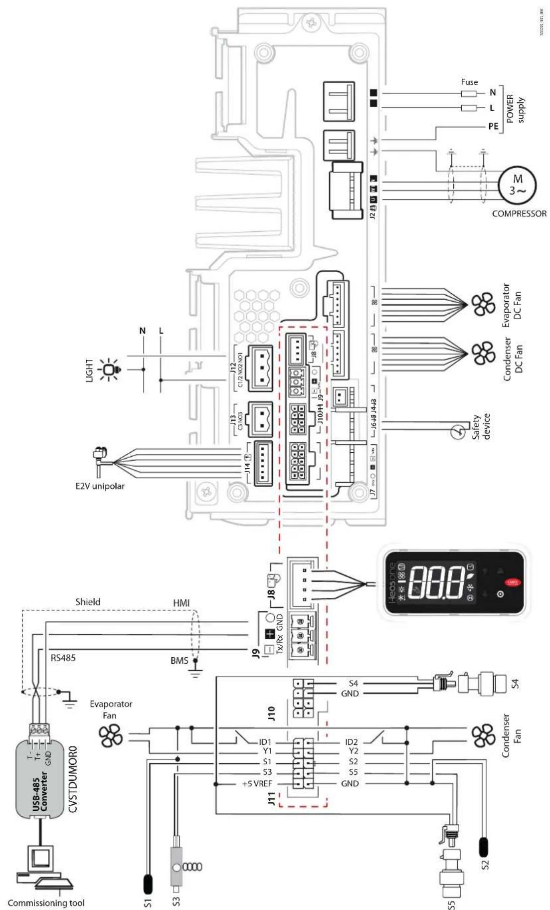
Fig. 3.aa
Notice: probes S4 and S5 in the figure are ratiometric
4. USER INTERFACE
4.1 Introduction
The Heosone system uses the user terminal (P/N AX4000*) for displaying alarms and some key values, and for setting the main parameters. The terminal is fitted with a three-digit display with sign and decimal point, alarm buzzer, nine icons and a four-button keypad for navigating and setting the parameters. Moreover, the terminal features wireless connectivity and an NFC (Near Field Communication) or Bluetooth Low Energy interface, used for interaction with mobile devices (on which the CAREL "Appli-ca" app has been installed, available for IOS and on Google Play for the Android operating system).
Notice:
- NFC connectivity is only compatible with the Applica app for the Android operating system;
- user levels: U=user, S=service, M=manufacturer, see the parameter table.
The unit of measure of the displayed values can be changed by setting parameter /5.
| Code Description Def. Min Max UOM User User term. | |||||||
| /5 Unit of measure - 0="C/barq 1="F/psig 0 0 1 - M,5 No | |||||||
Tab. 4.a
The buzzer is disabled by setting parameter H8.
| Code Description Def. Min Max UOM User User term. | |||||
| H8 | Buzzer: 0=No, 1=Yes | 1 | 0 | 1 | M No |
Tab. 4.b
The information available on the user terminal and in the Applica app may vary according to the password entered and the configuration parameters set by the cooler manufacturer. See the parameter table.
4.1.1 User terminal

Key
1 main field
2 keypad
3 operating mode
Fig. 4.a
Notice: the user terminal only offers access to user and service-level parameters. Manufacturer-level parameters are set using the Applica app or the configuration software. See the parameter table.
4.1.2 Keypad
| Part number | Description |
| ↑ ↓UP - DOWN | Increase/decrease the valueScroll direct access functionsLED on: scroll menu, parameters, direct access functionsLED flashing: set parameter values |
| ◎ PRG | Pressed briefly:Save value and return to the parameter codeEnter direct access function menu (from main screen) and activate/deactivate functionsPressed and held (3 s):Enter programming mode or return to previous level without savingLED on: main screen/programming mode |
| ⚠ ALARM | Pressed briefly: display alarmsPressed and held (3s): reset alarmsLED on/flashing: acknowledged/active alarm |
Tab. 4.c
Notice: during navigation, the LED is on if the button is enabled, otherwise it is off.
4.1.3 Display
The icons provide information on device operation and/or the activation of certain functions, as shown in the table.
| Icon Description On Flashing | |||
| Compressor Active - | |||
| Evaporator fan Active - | |||
| Lights On - | |||
| Auxiliary output Active - | |||
| Clock Scheduler active - | |||
| Defrost Active Awaiting | |||
| Service Maintenance request - | |||
| HACCP Active - | |||
Tab. 4.d
4.1.4 Standard display
At start-up, the user terminal briefly shows "NFC", indicating that the NFC interface is available for communication with mobile devices, and then the standard display is shown. The display shows measurements in the range -50 and +150°C, according to the type of probe used. For 0 to 5 Vdc and active 0 to 10 Vdc or 4 to 20 mA probes the unit of measure is defined by the type of probe used. The decimal point can be disabled by setting a parameter (/6). Parameter /t1 is used to choose the variable to be shown on the display during normal operation:
| Code | Description | Def. | Min | Max | UOM | User | User term. |
| /t1 | Display on user terminal0 = Terminal disabled1 to 6 = Probe 1 to 67, 8 = Reserved9 = Control probe10 = Virtual probe11 to 14 = Probe 11 to 1415 = Control set point | 9 | 0 | 15 | - | M, S | No |
| /6 | Display decimal point: 0=Yes, 1=No | 0 | 0 | 1 | - | M, S | No |
Tab. 4.e
Programming mode
The controller can be programmed in three levels, with access to different parameters based on the password entered (see the parameter table):
- user (password = 0);
• service (password = 22);
• manufacturer (password = 44).
The user terminal only offers access to user and service-level parameters.
To access the manufacturer parameters, use the "Applica" app or commissioning software.
| Code | Description | Def. | UOM | Min | Max | User |
| PDU | User password | 0 | - | 0 | 999 | S |
| PDS | Service password | 22 | - | 0 | 999 | M |
| PDM | Manufacturer password | 44 | - | 0 | 999 | M |
Tab. 4.f
Procedure (from user terminal)
Use:
• PRG for 3 s to enter programming mode (see chap. 7 Commissioning);
- UP and DOWN to navigate the menu and set the values;
• PRG to display the parameter value and save the changes;
• PRG (3s) or ESC to return to the higher level.
4.1.5 Direct functions
The following functions can be activated directly from the keypad or via the app:
Icon Display Description Icon Display Description
| Lht Cabinet | light dEF Defrost | |
| *+ ☑ | Cnt Continuous cycle | |
| + √ | CLn Clean cabinet | |
Tab. 4.g
Procedure:


- Go to the standard display; 2. Press PRG: Lht is displayed, the UP and
DOWN buttons light up.
Press PRG to turn the light on/off: the icon will come on or go off.
Press DOWN to activate the next function
(Cnt) or press Esc to exit;
- Press PRG to activate the continuous cycle (Cnt). Press DOWN to activate the next function;


- Follow the previous steps
for all functions;
-
Select Esc to exit;
-
The standard display is shown
5. MENU DESCRIPTION
5.1 Menu tree
Notice:
the parameters displayed depend on the password entered. See User interface and the Parameter table; manufacturer parameters (M) can only be accessed using the Applica app or commissioning software.
The parameters accessible on the Heosone terminal are organised into a menu structure based on categories. In programming mode, the icons indicate the parameter category displayed, helping navigation.
Category Description
| UIS User interface setting parameters: probe reading, superheat, electronic valve opening percentage |
| Ctrl Control parameters: control set point, unit ON/OFF command |
| dEF Defrost setting parameters:• maximum interval between consecutive defrosts,• maximum defrost duration,• end defrost temperature |
| ALM Alarm parameters: high and low temperature alarm threshold, alarm delay, alarm log |
| Eud ExV valve parameters: superheat set point |
| CnF Configuration parameters: serial communication |
| ESC Exit the menu |
Tab. 5.a
6. CHECKS BEFORE COMMISSIONING
Before commissioning the unit, check that:
- the controller's output current is greater than or equal to the rated or maximum current specified for the compressor;
• the working voltage range is correct;
• the power cables are sized correctly; - the cross-section and maximum length of the compressor cables are correct, and that these are connected in accordance with the wiring diagrams;
- all of the controller's inputs are connected correctly.
- the instructions on installing the individual system components have been followed;
- the total maximum power of direct current (DC) fans complies with the value shown in the technical specifications table in all operating conditions. Higher power consumption will cause permanent damage to the controller;
7. COMMISSIONING
The Heosone configuration procedure can be run on the user terminal, a mobile device (with the Applica app), or computer (with commissioning software).
7.1 User terminal
Procedure:

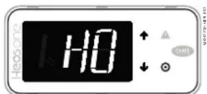
- Power on the controller and wait for the display to show the first parameter CM (Compressor model);

- Press PRG to display the parameter value;
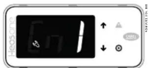
- Press UP/DOWN to modify the value;

- Press PRG to save the setting and return to the parameter code;
- Press UP/DOWN to go to the next parameter;
- Repeat points 2 to 5 for all commissioning parameters (see Table 7a);

- Press PRG to end the commissioning procedure (wizard);

- Wait for the standard display to be shown
Notice:
- the Service password also accesses the User parameters;
- if no button is pressed, after around 1 minute the terminal will automatically return to the standard display.
Mobile device
The "Applica" app can be used to configure the controller from a mobile device (smartphone, tablet), via NFC (Near Field Communication) and Bluetooth Low Energy (BLE). The app is used to configure the commissioning parameters and set groups of modifiable parameters according to specific needs (configurations). See Commissioning.
Table of initial configuration parameters
| Cat. Description Def Min Max UOM | |||||
| CM Compressor model (0 = FC-E40, 1 = FC-E57, 2 = FC-E100) 0 2 - | |||||
| H0 BMS serial address 199 1 247 - | |||||
| H3 BMS serial protocol (0 = CAREL, 1 = MODBUS) 1 0 1 - | |||||
| /P1 Type of probe, group 1 (S1, S2, S3) | 1 | 0 | 5 | - | |
| 0 = PT1000 Standard Range 3 = Reserved | |||||
| 1 = NTC Standard Range 4 =Reserved | |||||
| 2 = Reserved 5 = NTC-HT | |||||
| P1 Electronic valve: 0 = not present, 1 = OnBoard driver | 1 0 1 - | ||||
| /P2 Type of probe, group 2 (S4, S5) | 6 | 1 | 6 | - | |
| 1 = NTC Standard Range 4 = Rescived | |||||
| 2 = 0-5 V | 5 = NTC-HT | ||||
| 3 = 4-20 mA | 6 = 0.5-4.5V | ||||
| /P3 Type of probe, group 3 (S6) | 1 | 0 | 6 | - | |
| 0 = PT1000 Standard Range 4 = 0-10V | |||||
| 1 = NTC Standard Range 5 = NTC HT | |||||
| 2 = 0-5 V | 6 = 0.5-4.5V | ||||
| 3 = 4-20 mA | |||||
| /Fd Assign superheated gas temperature probe position (tGS) | 3 | -4 | 6 | - | |
| 0 = Function disabled | 6 = S6 | ||||
| 1 = S1 | -1 = S11: serial probe | ||||
| 2 = S2 | -2 = S12: serial probe | ||||
| 3 = S3 | -3 = S13: serial probe | ||||
| 4 = S4 | -4 = S14: serial probe | ||||
| 5 = S5 | |||||
| /FE Assign saturated evaporation pressure/temperature probe position (PEu/tEu) | 4 | -4 | 6 | - | |
| 0 = Function disabled | 6 = S6 | ||||
| 1 = S1 | -1 = S11: serial probe | ||||
| 2 = S2 | -2 = S12: serial probe | ||||
| 3 = S3 | -3 = S13: serial probe | ||||
| 4 = S4 | -4 = S13: serial probe | ||||
| 5 = S5 | |||||
| /AJE Maximum value for saturated evap. pressure/temp. probe (PEu/tEu) | 9.3 | /LE | 200 | barg (psig). | |
| /LE Minimum value for saturated evap. pressure/temp. probe (PEu/tEu) | -1 | -1 | /UE | barg (psig) | |
| End End commissioning wizard | - | - | - | - | |
Tab. 7.a
7.2 Mobile device
The "Applica" app can be used to configure the controller from a mobile device (smartphone, tablet), via NFC (Near Field Communication) or Bluetooth Low Energy (BLE). Heosone is fitted with an internal clock for managing store opening hours. The opening and closing times can be set and this time band enabled for each day of the week using the Applica app.
Procedure (modify parameters):
- download the CAREL "Applica" app;
- (on the mobile device) enable communication and mobile data;
- open Applica;
- move the mobile device near to the user terminal again to recognise the configuration;
- enter the password (*);
- set the parameters as needed;
- move the mobile device near to the user terminal again to upload the configuration parameters.

Fig. 7.a
(*) pre-assigned by the cooler manufacturer to allow maintenance only by authorised service technicians. See the parameter table.
Caution: during the first connection, Applica aligns itself with the software version on the Heosone system via a cloud connection; this means a mobile data connection is needed at least for this first connection.
7.3 Computer
The configuration software can be used to configure the commissioning parameters from a PC.
Procedure:

flowchart
graph LR
    A["Commissioning tool"] --> B["CVSTDUMOR0"]
    B --> C["RS485"]
    C --> D["BMS"]
    C --> E["HMI"]
    B --> F["Shield"]
    F --> G["GND"]
    G --> H["T+"]
    H --> I["T-"]
    I --> J["Ground"]
Fig. 7.b
- Connect the PC to connector J9 (BMS) via a USB/RS485 converter (P/N CVSTDUMOR0);

Fig. 7.c
- After starting the software, open the project file provided by Carel;
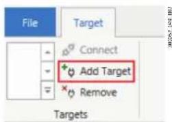
Fig. 7.d
- In the "Target" tab add a "target", i.e. the Heosone controller to communicate with;

Fig. 7.e
- Set the serial communication type and modify the connection parameters, as shown in the figure. Click "Connect": the list of parameters currently loaded on the controller is shown. The "Connect" icon changes to "Disconnect".
Notice: the serial port number (COM) may vary and depends on the devices actually connected to the computer..

- In the "value" column, enter the desired value for the parameters being modified and confirm by pressing ENTER.
Main commissioning parameters
| Code | Description | Def | Min | Max | UOM | |
| St Control set point 50 r1 r2 °C (°F) | ||||||
| P3 Superheat control set point 10 0 25 K | ||||||
| P4 Proportional gain for superheat control 15 0 100 | ||||||
| P5 Integral time for superheat control0 = function disabled | 150 0 900 s | |||||
| P6 Derivative time for superheat control0 = function disabled | 5 0 100 s | |||||
| cPr PID control: proportional gain 2 0 100 %/°C | ||||||
| ctl PID control: integral time 100 0 900 s | ||||||
| cdt | PID control: derivative time | 0 0 100 s | ||||
| d0 | Type of defrost0 = heater by temperature1 = hot gas by temperature2 = heater by time3 = hot gas by time4 = heater by time with temperature control | 0 | 0 | 4 | ||
| dt1 | End defrost temperature (read by Sd) | 8 | -50 | 50 | °C (°F) | |
| dP1 | Maximum defrost duration | 45 1 240 min | ||||
| dd Dripping time after defrost (fans off)0 = no dripping | 2 0 15 min | |||||
| Fd | Post-dripping time after defrost (fans off with control active) | 2 | 0 | 15 | min | |
| tS1-d | Start time band 1 - day | 0 0 11 - | ||||
| 0 = disabled | 6 = Sat | |||||
| 1 = Mon | 7 = Sun | |||||
| 2 = Tue | 8 = Mon to Fri | |||||
| 3 = Wed | 9 = Mon to Sat | |||||
| 4 = Thurs | 10 = Sat & Sun | |||||
| 5 = Fri | 11 = every day | |||||
| tS1-hh | Start time band 1 - hours 0 0 23 h | |||||
| tS1-m Start time band 1 - minutes 0 0 59 min | ||||||
| td1-d | Defrost 1 - day | 0 0 11 - | ||||
| 0 = disabled | 6 = Sat | |||||
| 1 = Mon | 7 = Sun | |||||
| 2 = Tue | 8 = Mon to Fri | |||||
| 3 = Wed | 9 = Mon to Sat | |||||
| 4 = Thurs | 10 = Sat & Sun | |||||
Tab. 7.b
* U: User; S: Service; M: OEM
8. FUNCTIONS
8.1 Inputs and outputs
Heosone features up to 6 analogue inputs and 5 digital inputs. See the description of the terminals in the paragraph "Description of the terminals".
The probes (temperature NTC, PT1000, 0-5 Vdc, 0.5-4.5 Vdc ratiometric and active probes), can be connected to the analogue inputs, and have been divided into 3 groups, with the same type of probe for each group. See the table of commissioning parameters.
| Probes Outputs (Y1, | |||||
| Passive Active | |||||
| NTC (-50T90°C) | NTC-HT (-30T150°C) | Pt1000 (-50T150°C) | 0 to 5Vdc | Rat. 0.5 to 4.5Vdc | 4 to 20 mA 0 to 10Vdc 0 to 10Vdc |
Tab. 8.a
8.1.1 Probes (analogue inputs)
| Analogue input | S1 | S2 | S3 | S4 | S5 | S6 |
| Parameter for type of probe | /P1 | /P2 | /P3 | |||
| PT1000 Standard (range -50T150°C) | x | x | x | x | ||
| NTC Standard (range -50T90°C) | x | x | x | x | x | x |
| NTC-HT (range -30T150°C) | x | x | x | x | x | x |
| 0 to 5 Vdc | xxx | |||||
| Ratiometric 0.5 to 4.5 Vdc | xxx | |||||
| 4-20 mA input | xxx | |||||
| 0-10 Vdc input | x | |||||
Tab. 8.b
Caution: for the maximum current that can be supplied to the ratiometric probes, see the technical specifications table.
Inputs S4, S5 and S6 can be connected to 0-5 V ratiometric pressure transducers, 0.5-4.5 ratiometric probes and active probes with 4-20 mA or 0-10 V output (S6 only). All of these probes require the range of measurement to be defined, set by the relative minimum and maximum parameters for the function associated with the probe. See the parameter table. To assign the function to each physical or serial probe, configure parameters /FA, /Fb, ... /Fy. See the parameter table.
| Probe | Par. |
| Outlet temperature (Sm) | /FA |
| Defrost temperature (Sd) | /Fb |
| Intake temperature (Sr) | /Fc |
| Superheated gas temperature (tGS) | /Fd |
| Saturated evaporation pressure/temperature (PEu/tEu) | /FE |
| Defrost temperature 2 (Sd2) | /FF |
| Auxiliary temperature 1 (Saux1) | /FG |
| Auxiliary temperature 2 (Saux2) | /FH |
| Probe | Par. |
| Room temperature (SA) | /Fl |
| Room humidity (SU) | /FL |
| Glass temperature (Svt) | /FM |
| Dew point temperature (SdP) | /Fn |
| Discharge temperature (Sdt) | /Fo |
| Condensing pressure (Scp) | /Fs |
| Condensing temperature (Sc) | /Fy |
| Tab. 8.c | |
Assign probe functions (parameters /FA, /Fb, /Fc, /Fd, /Fe)
| Code | Description | Def. | Min | Max | UOM | User | User term. |
| /FA Assign outlet temperature probe (Sm) | 1 | -4 | 6 | - | M, S | No | |
| 0 = Function disabled 4 = Probe S4 -2 = Serial probe S12 | |||||||
| 1 = Probe S1 5 = Probe S5 -3 = Serial probe S13 | |||||||
| 2 = Probe S2 6 = Probe S6 -4 = Serial probe S14 | |||||||
| 3 = Probe S3 -1 = Serial probe S11 | |||||||
| /Fb | Assign defrost temperature probe (Sd) - see /FA | 2 | -4 | 6 | - | M, S | No |
| /Fc | Assign intake temperature probe (Sr) - sec /FA | 0 | -4 | 6 | - | M, S | No |
| /Fd | Assign superheated gas temperature probe (tGS) - see /FA | 3 | -4 | 6 | - | M, S | Yes |
| /Fe | Assign saturated evaporation pressure/temperature probe (PEu/tEu) - see /FA | 4 | -4 | 6 | - | M, S | Yes |
Tab. 8.d
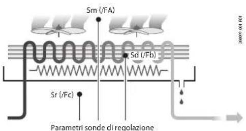
Heosone, inside the showcase or cold room, can use temperature probes to measure:
• the air outlet temperature (at the evaporator outlet);
- the defrost temperature (in contact with the coldest point of the evaporator);
• the air intake temperature (at the evaporator inlet).
The default configuration for assigning the control probes is as follows:
• S1 = Outlet probe (Sm);
• S2 = Defrost probe (Sd);
The intake probe (Sr) is not configured by default.
The default configuration also involves these three probes being standard CAREL NTC. However, other types of probes can be connected by setting parameter /P1. On Heosone the default settings can be changed to choose the function associated with any of the probes connected. There are also cases where the characteristics of the applications require different settings.
Heosone also requires two other probes to calculate the superheat:
• saturated evaporation temperature/pressure probe;
• superheated gas temperature probe.
The default configuration for assigning the control probes is as follows:
- S3 = Superheated gas temperature probe (tGS)
- S4 = Saturated evaporation temperature/pressure probe (tEu/PEu).
Calibration (parameters /cA, ... /cy)
On Heosone the values read by the probes can be calibrated by setting parameters /FA, ... /Fy, based on the different functions and some internal variables. In particular, parameters /cA, .../cy are used to increase or decrease the values read by the probes connected to the analogue inputs across the range of measurement. Parameter /cE, on the other hand, corrects the value of the saturated evaporation temperature calculated directly based on the evaporation pressure.
Caution:
HACCP: this modification may not be allowed by HACCP procedures as it alters the measured value. Verify that you have authorisation and record the changes where required.

line
| T1 | T2 | |---|---| | min | A | | max | max |Fig. 8.b
| Ref. | Description |
| T1 | Outlet temperature read by the probe |
| T2 | Outlet temperature (value calibrated by T1) |
| A | Offset (example: parameter /ac for outlet probe) |
| min, max | Field of measurement |
| Code | Description | Def. | Min | Max | UOM | User | User term. |
| /ca | Outlet temperature probe (Sm) calibration | 0 | -20 | 20 | °C (°F) | M, S | No |
| /cb | Defrost temperature probe (Sd) calibration | 0 | -20 | 20 | °C (°F) | M, S | No |
| /cc | Intake temperature probe (Sr) calibration | 0 | -20 | 20 | °C (°F) | M, S | No |
| /cE | Saturated evaporation pressure probe (PEu) calibration | 0 | -20 | 20 | barq (psig) | M, S | No |
| /cF | Defrost temperature probe 2 (Sd2) calibration | 0 | -20 | 20 | °C (°F) | M, S | No |
| /cG | Auxiliary temperature probe 1 (Saux1) calibration | 0 | -20 | 20 | °C (°F) | M, S | No |
| /cH | Auxiliary temperature probe 2 (Saux2) calibration | 0 | -20 | 20 | °C (°F) | M, S | No |
| /cl | Ambient temp. probe (SA) calibration | 0 | -20 | 20 | °C (°F) | M, S | No |
| /cl | Ambient humidity probe (SU) calibration | 0 | -20 | 20 | %RH | M, S | No |
| /cM | Glass temperature probe (Svt) calibration | 0 | -20 | 20 | °C (°F) | M, S | No |
| /cn | Dewpoint value (SdP) calibration | 0 | -20 | 20 | °C (°F) | M, S | No |
| /co | Discharge temperature probe (Sd) calibration | 0 | -20 | 20 | °C (°F) | M, S | No |
| /cs | Condensing pressure probe (Scp) calibration | 0 | -20 | 20 | bar (psi) | M, S | No |
| /cy | Condensing temperature probe (Sc) calibration | 0 | -20 | 20 | °C (°F) | M, S | No |
Tab. 8.e
/2: analogue probe measurement stability
| Code | Description | Def. | Min | Max | UOM | User | User term. |
| /2 | Analogue probe measurement stability | 9 | 1 | 15 | M, S | No |
Tab. 8.f
The setting of /2 defines the coefficient used to stabilise the temperature measurement.
Low values assigned to this parameter allow a prompt response of the sensor to temperature variations; the reading however become more sensitive to disturbance.. High values slow down the response, but guarantee greater immunity to disturbance, that is, a more stable, precise and filtered reading.
8.1.2 Digital inputs
Heosone can manage up to five physical digital inputs. To associate a physical input to each available function, set parameters DIA, Dlb, ... Dls to the value relating to the physical digital input.
Digital input functions
| Contact | |||
| Digital input assignment for: Par. Open Closed | |||
| immediate external alarm DIA Active Not active | |||
| delayed external alarm Dlb Active Not active | |||
| enable defrost Dlc Not enabled Enabled | |||
| start defrost Dld Not active Active | |||
| door switch with stopping control | DIE Door open | Door closed | |
| remote ON/OFF | DIF OFF | ON | |
| curtain switch/light | DIG | Day status | Night status |
| start/stop continuous cycle | DIH | Not active Active | |
| digital input monitoring | DII | Active Not active | |
| timed digital input | DII. Active Not active | ||
| switch to Standby status | DIM | Active Not active | |
| switch to Clean status | DIn Active Not active | ||
| door switch without stopping control | Dlp Door open | Door closed | |
| defrost corresponding to digital input status | Dlr | Not active | Active |
| digital input for generic alarm function | Dls | Active Not active | |
Tab. 8.g
Parameters rIA, rIb,..., rIs can be used to reverse the logic of the functions associated with the digital inputs.
| Code | Description | Def. | Min | Max | UOM | User | User term. |
| rIA, rIb,...rls | Reverse digital input logic | 0 | 0 | 1 | - | M | No |
Tab. 8.h
Immediate external alarm (par. DIA)
Activation of the alarm causes:
- message "IA" shown on the display and ALARM flashing;
- activation of the buzzer (see par. H8);
- activation of the alarm relay (see par. DOb);
• control stops;
• defrost stopped immediately (if in progress).
Notice: activation of the external alarm shuts down the evaporator fans only if these follow the status of the compressor output, as set for parameter /F2. When the compressor is shut down due to an external alarm the compressor minimum ON time is ignored (parameter c3).
| Code | Description | Def. | Min | Max | UOM | User | User term. | |
| DIA | Assign digital input for immediate external alarm | 0 | 0 | 5 | - | M, 5 | No | |
| 0 = Function disabled | 3 = digital input 3 (ID3) | |||||||
| 1 = digital input 1 (ID1) | 4 = digital input 4 (ID4) | |||||||
| 2 = digital input 2 (ID2) | 5 = digital input 5 (ID5) | |||||||
Tab. 8.i
Delayed external alarm (par. Dlb)
The behaviour of this alarm is the same as for the immediate external alarm, with a delay in activation (parameter A11). If set to 0, the alarm is signal-only.
| Code | Description | Def. | Min | Max | UOM | User | User term. |
| Dlb | Assign delayed external alarm digital input - see DIA | 0 | 0 | 5 | - | M_rS | No |
Tab. 8.j
Enable defrost (par. Dlc)
Used to disable any defrost calls. When the contact is open, all defrost calls are ignored. Par. d5 can be used to delay activation.
Notice: if the contact is open while a defrost is in progress, this is immediately stopped, the defrost icon flashes on the display indicating the defrost call is active (this starts again when the contact closes); this function may be useful to prevent defrosts on units exposed to the public during store opening hours.
| Code | Description | Def. | Min | Max | UOM | User | User term. |
| Dlc | Assign enable defrost digital input - see DIA | 0 | 0 | 5 | - | M, S | No |
Tab. 8.k
Start defrost (par. Dld)
Closing the digital contact starts a defrost, if enabled.
The defrost digital input can be used effectively to perform real time defrosts.
Notice: if the defrost is disabled by another digital input configured as "enable defrost", the defrost calls are ignored.
| Code | Description | Def. | Min | Max | UOM | User | User term. |
| Dld Assign start defrost digital input - see DIA 0 0 5 - M, S No | |||||||
| d5 | Defrost delay at power on 0 = delay disabled | 0 | 0 | 240 | min | M, S | No |
Tab. 8.1
Door switch with stopping control (par. DIE)
Door open:
- stop control (compressor and evaporator fans off); alternatively, control can be kept active by setting parameter DIP (see the description below);
• light on (see par. DOE); - ALARM flashing;
• disable temperature alarms.
Door closed:
- resume control;
• light off (see par. DOE) with delay set by par. H14;
• ALARM stops flashing; - enable temperature alarms with delay Ad after bypass time defined by par. Add.
| Code | Description | Def. | Min | Max | UOM | User | User term. |
| DIE | Assign digital input for door switch with compressor and evaporator fans off - see DIA | 0 | 0 | 5 | M, S | No | |
| DOE | Assign light digital output - see DOb | 0 | 3 - M | No | |||
| H14 | Time light stays on after closing the door | 0 | 0 | 240 | min | M, S | No |
| Ad | Delay time for high and low temp, alarms (AH, AL) | 120 | 0 | 240 | min | M, S | Yes |
| Add | High temp, alarm bypass time for door open | 30 | 1 | 240 | min | M, S | No |
| Idoor | Door open: alarm delay | 30 | 1 | 240 | min | M | No |
Tab. 8.m
Caution: check compatibility of disabling/delaying the alarm with the site's HACCP procedures.
Notice:
- when control resumes, the compressor times are observed;
- if the door remains open for longer than the value of par. Tdoor, control resumes in any case. The light remains on, the measurement shown on the display flashes, the buzzer and the alarm relay are activated, and the temperature alarms are enabled with delay Ad.
Remote ON/OFF (par. DIF)
When the controller is OFF:
- the user terminal shows the value measured by the set probe (parameter /t1) alternating with the message OFF;
• the auxiliary relays set as AUX and light remain active, while the other auxiliary outputs are deactivated;
• the buzzer and alarm relay are deactivated;
- the following are not performed: control, defrosts, continuous cycle, temperature alarm signals;
• the compressor protection times are observed.
When the controller is ON again, all the functions are reactivated, except for the defrost on start-up and compressor and evaporator fan delay at power on (par. c0).
Notice:
- the OFF command from digital input has priority over those from the keypad or supervisor;
- if the controller remains OFF for a longer time than the value set for parameter dl, a defrost is performed when the controller is switched on again.
| Code | Description | Def. | Min | Max | UOM | User | User term. |
| DIF | Assign remote ON/OFF digital input - see DIA | 0.0 | 5 - M, S | No | |||
| d1 | Maximum interval between consecutive defrosts | 8 | 0 | 240 | h | M, S, U | Yes |
| c0 | Delay to enable compressor and evaporator fans at power on | 0 | 0 | 240 | min | M, S | No |
Tab. 8.n
Curtain switch (par. DIG)
During night status:
- the night-time set point Stn is used for control, calculated based on the set point St plus the offset defined by parameter r4 (Stn = St + r4). The control probe can also be modified according to the setting of parameter r6 (0 = virtual probe, 1 = probe), see the paragraph "Control";
- the AUX or light output is deactivated according to the setting of parameter H9.
During day status:
- normal operation resumes: set point = St, virtual probe used as control probe;
- AUX or light output activated according to the setting of parameter H9.
| Code | Description | Def. | Min | Max | UOM | User | User term. |
| DIG Assign curtain switch digital input - see DIA 0 0 5 - M, S No | |||||||
| H9 | Output switched with time bands 0 = Light; 1 = AUX | 0 | 0 | 1 | - | M, S | No |
| r4 | Automatic night set point variation | 0 | -50 | 50 | °C (°F) | M | No |
| r6 | Probe for night-time control: 0=virtual probe Sv, 1=intake probe Sr | 0 | 0 | 1 | - | M | No |
Tab. 8.0
Start/stop continuous cycle (par. DIH)
- When the contact is closed, the continuous cycle is activated, based on parameters cc and c6.
- When the contact opens again, the continuous cycle is deactivated.
| Code | Description | Def. | Min | Max | UOM | User | User term. |
| DIG Assign curtain switch digital input - see DIA 0 0 5 - M, S No | |||||||
| cc | Running time in continuous cycle: 0 = Disabled | 0 | 0 | 15 | h | M | No |
| c6 | Low temp. alarm bypass time after continuous cycle | 60 | 0 | 240 | min | M | No |
Tab. 8.p
Digital input monitoring (par. DII)
- The supervisor is able to detect the status of the digital input.
- The value depends on the possible reversing of the input logic using parameter rll.
| Code | Description | Def. | Min | Max | UOM | User | User term. |
| DII | Assign input status monitoring digital input - see DIA | 0 | 0 | 5 | - | M, S | No |
| rII | Input status monitoring digital input logic - see rIA | 0 | 0 | 1 | - | M | No |
Tab. 8.q
Timed input (timer) (par. DIL)
The timed digital input is a special configuration that allows, in the transition from not active to active, the activation status of a specific digital variable to be maintained on the supervisor for a time set by parameter. To enable the function, select the desired digital input using parameter DIL.
When a digital input is configured as a timed digital input and a transition occurs from not active to active, the BAS_DIL "Timer" supervisor variable is set to ON and remains ON regardless of the physical status of digital input for the time set by parameter dlt. Setting parameter dlt to 0 disables the function. The "Timer" variable can be associated with one or more AUX digital outputs (relays) by suitably setting the related parameter DOo to the value 13, thus aligning it with the status of the "Timer" variable. The timed digital input can be controlled not only by a physical digital input but also from the supervisor using the related digital control variable, with the same result. The same function can be used to set the "Timer" variable OFF regardless of whether or not the time set for parameter dlt has elapsed.
Special features:
- when the "Timer" variable is ON, another transition from OFF to ON of the same digital input resets the timer.
| Code | Description | Def. | Min | Max | UOM | User | User term. |
| DIL | Assign timed digital input - see DIA | 0 | 0.5 | - M, S | No | ||
| dlt | Timer duration (timed input): 0 = function disabled | 0 | 0 | 999 | min | M, S | No |
| DOo | Assign timed digital output - see DOb | 0 | 0.3 - M | No |
Tab. 8.r
Switch to Standby status (par. DIM)
Standby status is an intermediate state between ON and OFF: control is interrupted, the expansion valve is closed (0%), the control alarms and probe alarms remain active. ON status (normal operation) resumes after the time Stt has elapsed, after switching off (OFF status) or when the controller is restarted.
| Code | Description | Def. | Min | Max | UOM | User | User term. |
| DIM | Assign digital input for switching to Standby mode - see DIA | 0 | 0 | 5 | - | M, S | No |
| Stt | Maximum time for Standby status | 0 | 0 | 240 | min | M | No |
Tab. 8.s
Switch to Clean status (par. Dln)
Clean status is an intermediate state between ON and OFF: control is interrupted, the expansion valve is closed (0%), and only the probe alarms remain active.. ON status (normal operation) resumes after the time CLt has elapsed, after switching off (OFF status) or when the controller is restarted.
| Code Description | Def. | Min | Max | UOM | User | User term. |
| Dln Assign digital input for switching to Clean mode - see DIA 0 0 5 - M, S No | ||||||
| CLt Max time for Clean status 0 0 999 min M No |
Tab. 8.t
The meaning of each status, OFF, ON, Standby and Clean, is summarised in the following table:
| Unit OFF | Unit ON | Standby | Clean | |
| Control | OFF | ON | OFF | OFF |
| Light | independent | independent | independent | independent |
| Probe alarms | enabled | enabled | enabled | enabled |
| Other alarms | disabled | enabled | enabled | disabled |
| User terminal | OFF | based on /t1 | Stb | CLn |
Tab. 8.u
Door switch without stopping control (par. DIP)
Operating mode that allows the door to be opened without stopping control. In this case, when opening the door, only the light will switch on. This operating mode can be configured by setting parameter DIP with one of the digital inputs. Opening the door introduces a temperature alarm delay as described for the door switch function (par. DIE).
| Code | Description | Def. | Min | Max | UOM | User | User term. |
| Dlp | Assign door switch without control stop digital input - see DIA | 0 | 0 | 5 | - | M, S | No |
Tab. 8.v
Start/stop defrost from digital input (par. Dlr)
If configured in this new mode, a digital input can be used to start a defrost when closing and end the defrost when opening (independently of par. d0).
If the defrost ends after the maximum time (par.dP1), alarm Ed1 is activated if enabled (r3 = 1) .
| Code | Description | Def. | Min | Max | UOM | User | User term. |
| Dlr | Assign digital input for defrost according to DI status - see DIA | 0 | 0 | 5 | - | M, S | No |
| dP1 | Maximum defrost duration | 45 | 1 | 240 | min | M, S, U | Yes |
| r3 | End defrost signal by timeout: 0=disabled, 1=enabled | 0 | 0 | 1 | - | M | No |
Tab. 8.w
8.1.3 Analogue outputs
Heosone has the following analogue outputs: Y1, Y2, type 0-10 V. The two analogue outputs can be used to manage the functions summarised in the following table.
| Code | Description | Def. | Min | Max | UOM | User | User term. |
| /AA | Assign analogue output for modulating evaporator fans0 = not configured 1 = analogue output 1 (Y1) 2 = analogue output 2 (Y2) | 0 0 2 - | M,S | No | |||
| /Ac | Assign analogue output for modulating anti-sweat heaters - see /AA | 0 | 0 | 2 | - | M,S | No |
| /Ad | Assign analogue output for generic function - see /AA | 0 | 0 | 2 | - | M,S | No |
| /Ac | Assign channel for modulating condensing fan output - see /AA | 0 | 0 | 2 | - | M,S | No |
Tab. 8.x
8.1.4 Digital outputs
Heosone has three digital outputs: NO1, NO2, NO3. To associate the digital outputs with the available functions, set parameters DOb, ... DOt to the value of the physical digital output.
Caution: observe the maximum allowable current limits on the relays. See the technical specifications table.
Digital output functions
| Digital output assignment for: | Par. | Digital output assignment for: | Par. |
| Alarm | DOb | Condensate drain heater | DOP |
| Auxiliary | DOc | Anti-sweat heater | DOQ |
| Defrost | DOG | Generic stage function output | DOs |
| Light | DOE | Condenser fans | Dot |
| Evaporator fans | DOI | Hot gas defrost soienoid | DOAA |
| Output associated with the timer function | DOo | Tab. 8.y | |
Parameters rOb, ..., rOt can be used to reverse the logic of the functions associated with the digital inputs.
| Code | Description | Def. | Min | Max | UOM | User | User term. |
| rOb,...rOt | Digital output logic: 0=direct, 1=reverse | 0 | 0 | 1 | - | M | No |
Tab. 8.z
Alarm (par. DOb)
The relay associated with the alarm function can work as follows:
• normally de-energised: the relay is energised when an alarm occurs (rOb = 0);
• normally energised: the relay is de-energised when an alarm occurs (rOb = 1);
Notice: operation with the relay de-energised (rOb = 1) when an alarm occurs ensures maximum safety when the alarm is due to a power failure or power cable disconnection.
| Code | Description | Def. | Min | Max | UOM | User | User term. |
| DOb A | Assign alarm digital output | 0 | 0 | 3 | - | M | N |
| 0 = not configured | |||||||
| 1 = digital output 1 (NO1) | |||||||
| 2 = digital output 2 (NO2) | |||||||
| 3 = digital output 3 (NO3) |
Tab. 8.aa
Auxiliary (par. DOc)
The actuator can be activated/deactivated using a command from the supervisor and based on the changeover in day/night status (linked to the curtain switch or the setting of the time bands); activation/deactivation of the actuator is signalled by the AUX icon switching on/off. The AUX output to be activated or deactivated based on the night/day time band can be selected (see parameters tS1...8, tE1...8 and H9).
| Code | Description | Def. | Min | Max | UOM | User | User term. |
| DOc | Assign digital output for auxiliary output - see DOb | 0 | 0 | 3 | - | M | No |
| H9 | Output switched with time bands 0 = Light; 1 = AUX | 0 | 0 | 1 | - | M | S N |
Tab. 8.ab
Light (par. DOE)
The actuator can be activated/deactivated directly using the functions on the user terminal, using a command from the supervisor and based on the changeover in day/night status (linked to the curtain/door switch or the setting of the time bands); activation/deactivation of the actuator is signalled by the light icon switching on/off. The light output to be activated or deactivated based on the night/day time band can be selected (see parameters tS1...8, tE1...8 and H9).
| Code | Description | Def. | Min | Max | UOM | User | User term. |
| DOE | Assign light digital output - see DOb | 0 | 0 | 3 | - | M | No |
Tab. 8.ac
Defrost (par. DOG)
The actuator is activated/deactivated based on the defrost settings (see the paragraph "Defrost"). Activation/deactivation of the actuator is signalled by the defrost icon switching on/off on the user terminal.
| Code | Description | Def. | Min | Max | UOM | User | User term. |
| DOG | Assign defrost digital output - see DOb | 0 | 0 | 3 | - | M | No |
Tab. 8.ad
Evaporator fans (par. DOI)
Once the digital output has been selected, the evaporator fan on/off is signalled by the evaporator fan icon switching on/off on the display. See the paragraph "Evaporator fans"
| Code | Description | Def. | Min | Max | UOM | User | User term. |
| DOI | Assign evaporator fan digital output - see DOb | 0 | 0 | 3 | - | M | No |
Tab. 8.ae
Condensate drain heater (par. DOP)
During defrosting there may be frozen condensate on the bottom of the cabinet that prevents the water thawed from the evaporator from being drained correctly. The digital output can be configured to manage the condensate drain heater function. The heater is started on activation of the pump down stage and stays on throughout the defrost procedure, until the end of the dripping phase. The heater can be activated by selecting a digital output with par. DOP.
Notice: the heater must be protected against overheating (e.g. thermal protector).
| Code | Description | Def. | Min | Max | UOM | User | User term. |
| DOP | Assign condensate drain heater digital output - see DOb | 0 | 0 | 3 | - | M | No |
Tab. 8.af
Anti-sweat heater (par. DOQ)
Select the digital output for demisting the glass (control with fixed activation, see the paragraph "Anti-sweat heaters").
| Code | Description | Def. | Min | Max | UOM | User | User term. |
| DOQ | Assign anti-sweat heater digital output - see DOb | 0 | 0 | 3 | - | M | No |
Tab. 8.ag
Generic stage function (par. DOS)
Select the digital output for configuring a generic stage function.
| Code Description | Def. | Min | Max | UOM | User | User term. |
| DOS Assign generic stage function digital output - see DOb 0 0 3 - M No |
Evaporator fans (par. DOt)
Select the digital output for activation of the condenser fans (see paragraph "Condenser fans").
| Code Description | Def. | Min | Max | UOM | User | User term. |
| DOt Assign condenser fan digital output - see DOb 0 0 3 - M No |
Hot gas defrost solenoid (par. DOAA)
Select the digital output for the hot gas injection solenoid during defrost (see paragraph "Hot gas defrost").
| Code | Description | Def. | Min | Max | UOM | User | User term. |
| DOAA | Assign hot gas injection solenoid digital output - see DOb | 0 | 0 | 3 | - | M | No |
8.2 Control
Introduction
There are various modes for controlling air temperature for the preservation of foodstuffs in cold rooms and showcases. The following figure shows the position of the intake probe Sr and the outlet probe Sm. The virtual probe Sv is a weighted average of these two, based on parameter /4, according to the following formula:
$$ S v = \frac {S m \cdot (1 0 0 - / 4) + S r \cdot (/ 4)}{1 0 0} $$
| Code | Description | Def. | Min | Max | UOM | User | User term. |
| /4 | Virtual probe composition: 0 = Outlet probe Sm, 100 = Intake probe Sr | 0 | 0 | 100 | % | 5 | No |
For example, if /4=50, Sv=(Sm+Sr)/2 represents an estimated value of the air temperature around the refrigerated food.
Notice: HACCP: parameter /4 can be set to change the temperature used for control and for display. This operation may be prohibited by HACCP procedures or require record keeping and authorisation.
Example: vertical showcase

| Ref. | Description |
| Sm | Outlet probe |
| Sr Intake | probe |
| Sv | Virtual probe |
Fig. 8.c
During the day, most of the load in a refrigerated showcase is due to warm air that enters from the outside and mixes with the cold air inside. Control based on the intake probe, due to high temperature outside the showcase and the mixing of the air, may not manage to reach the set point. Displaying the intake temperature would show a temperature that is too high. Setting a set point that is too low for the intake probe Sr may cause the food to freeze. On the other hand, displaying the outlet temperature would show a temperature that is too low. Consequently, the display of the control probe, set point or virtual probe can be configured using parameter /t1.
On Heosone, the temperature is controlled by modulating the compressor speed based on the cooling request, with proportional+integral+derivative (PID) control.
To ensure control stability, in addition to the working set point (St), the corresponding parameters need to be adjusted, namely proportional gain (cpr), integral time (cti) and derivative time (cdt).
| Code | Description | Def. | Min | Max | UOM | User | User term. |
| cdt PID | control: derivative time 0 0 100 s M,S No | ||||||
| cPr PID | control: proportional gain 2 0 100 %/°C M,S No | ||||||
| ctl | PID control: integral time | 100 0 900 s M,S No | |||||
Tab. 8.al
The proportional gain setting (cPr) influences the instantaneous speed at which the system reacts to a variation in the control temperature: as the gain increases, system reactivity increases, vice-versa lower values will reduce the reaction speed.
It should be noted that too-high proportional gain values may lead to instability and swings. The most appropriate integral time setting (ctl) allows further modification (increase or decrease) to the compressor speed if the control temperature remains away from the working set point. Higher values lead to a slower response, conversely lower values lead to a faster response in compensation.
System reactivity is influenced not only by parameter ctl, but also by how far the control temperature is away from the working set point: as the deviation from the set point increases, compressor speed will be compensated more. The derivative time setting (ctd) makes it possible to anticipate the reaction of the system in the event of sudden changes in working conditions (e.g. a significant change in the working set point). By default, the derivative time is disabled.
Minimum and maximum set point values (parameters r1 and r2)
Parameters r1 and r2 are used to define the minimum and maximum limits for the control set point.
| Code | Description | Def. | Min | Max | UOM | User | User term. |
| r1 | Minimum set point | -50 | -50 | r2 | °C (°F) | M | No |
| r2 | Maximum set point | 50 | r1 | 50 | °C (°F) | M | No |
Tab. 8.am
Night-time operation
During night-time operation the curtain on the display case is closed and consequently less cold inside air is mixed with warm outside air. Therefore, as a direct consequence, the thermal load decreases. The temperature of the air that cools the produce is near the outlet temperature, and therefore to avoid excessively low temperatures and reduce energy consumption, the set point needs to be increased at night, by setting parameter r4. Parameter r6 can then be used to possible the virtual probe Sv or intake probe Sr as the control probe. Naturally, the change to night-time operation must be signalled externally. This is usually done using the curtain switch, set with parameter DIG, signalling that the curtain has been lowered, or by setting the time bands (parameters tS1 to tS8 and tE1 to tE8) or from the supervisor.
| Code | Description | Def. | Min | Max | UOM | User | User term. |
| r4 | Automatic night set point variation | 0 | -50 | 50 | °C (°F) | M | No |
| r6 | Probe for night-time control: 0=virtual probe Sv, 1=intake probe Sr | 0 | 0 | 1 | - | M | No |
| tS1..8-d | Start time band 1 to 8: day - see (td1..8-d) | 0 | 0 | 11 | d | M, S, U | No |
| tS1..8-time | Start time band 1 to 8: time | 0 | 00:00 | 23:59 | - | M, S, U | No |
| tE1..8-d | End time band 1 to 8: day - see (td1..8-d) | 0 | 0 | 11 | d | M, S, U | No |
| tE1..8-time | End time band 1 to 8: time | 0 | 00:00 | 23:59 | - | M, S, U | No |
Tab. 8.an
Notice:
HACCP: verify that modification of the night-time set point (parameter /4) is permitted by site HACCP procedures. If required, obtain the required authorisation and record the changes.
| Variable | Daytime control | Night-time control | |
| r6 = 0 | r6 = 1 | ||
| Control probe (Sreg) | Virtual probe (5v) | Virtual probe (5v) | Intake probe (Sr) |
| Set point | St | St+14 | |
Tab. 8.ao

Fig. 8.d
During day status:
- Set point = St;
- light on;
• control on virtual probe Sv.
During night status: - Set point = St + r4;
• light off;
• control on Sr (if r6=1) or on Sv (if r6=0).
Weighted control
This function compensates for the disadvantages of control based solely on the outlet probe or the intake probe. The control probe becomes the virtual probe:
$$ S v = \frac {S m \cdot (1 0 0 - / 4) + S r \cdot (/ 4)}{1 0 0} $$
The weighted average of the outlet and intake probes is used to compensate for the mixing of air from outside the showcase. Normally the weight of /4 is set to 50% and the value of the virtual probe can be chosen for both display and temperature recording.
The value of the virtual probe thus becomes the mean value of the outlet and intake probes and the measurement that best corresponds to the temperature of the produce. Another advantage is automatic adaptation to night-time operation with the curtain closed, without needing an external signal. When the curtain is open there is immediately an increase in load on the evaporator, consequently the outlet temperature is lowered so as to keep the average temperature constant.

line
| t | Sr | Sv | Sm | | ---- | ---- | ---- | ---- | | 0 | 0 | 0 | 0 | | 1 | 0 | 0 | 0 | | 2 | 0 | 0 | 0 | | 3 | 0 | 0 | 0 | | 4 | 0 | 0 | 0 | | 5 | 0 | 0 | 0 | | 6 | 0 | 0 | 0 | | 7 | 0 | 0 | 0 | | 8 | 0 | 0 | 0 | | 9 | 0 | 0 | 0 | | 10 | 0 | 0 | 0 | | 11 | 0 | 0 | 0 | | 12 | 0 | 0 | 0 | | 13 | 0 | 0 | 0 | | 14 | 0 | 0 | 0 | | 15 | 0 | 0 | 0 | | 16 | 0 | 0 | 0 | | 17 | 0 | 0 | 0 | | 18 | 0 | 0 | 0 | | 19 | 0 | 0 | 0 | | 20 | 0 | 0 | 0 | | 21 | 0 | 0 | 0 | | 22 | 0 | 0 | 0 | | 23 | 0 | 0 | 0 | | 24 | 0 | 0 | 0 | | 25 | 0 | 0 | 0 | | 26 | 0 | 0 | 0 | | 27 | 0 | 0 | 0 | | 28 | 0 | 0 | 0 | | 29 | 0 | 0 | 0 | | 30 | 0 | 0 | 0 | | 31 | 0 | 0 | 0 | | 32 | 0 | 0 | 0 | | 33 | 0 | 0 | 0 | | 34 | 0 | 0 | 0 | | 35 | 0 | 0 | 0 | | 36 | 0 | 0 | 0 | | 37 | 0 | 0 | 0 | | 38 | 0 | 0 | 0 | | 39 | 0 | 0 | 0 | | 40 | 0 | 0 | 0 | | 41 | 0 | 0 | 0 | | 42 | 0 | 0 | 0 | | 43 | 0 | 0 | 0 | | 44 | 0 | 0 | 0 | | 45 | 0 | 0 | 0 | | 46 | 0 | 0 | 0 | | 47 | 0 | 0 | 0 | | 48 | 0 | 0 | 0 | | 49 | 0 | 0 | 0 | | 50 | 0 | 0 | 0 | | Note: The y-axis label is "night day". The x-axis label is "t". There are no additional data series in this image. The values for the series are labeled as "Sr", "Sv", or "Sm".Fig. 8.e
Ref. Description
| T temperature | |
| t time | |
| Sr Intake probe | |
| Sv Virtual probe | |
| Sm Outlet probe | |
ON/OFF (par. ON)
Parameter ON is used to switch the controller ON/OFF. If there is a digital input configured as remote ON/OFF, this has higher priority than the supervisor command or the ON parameter.
| Code | Description | Def. | Min | Max | UOM | User | User term. |
| ON | ON/OFF command 0=OFF, 1=ON | 1 | 0 | 1 | - | MS | No |
Tab. 8.ap
In this operating mode, the display shows the standard display, alternating with the message "OFF".
When OFF, the following are possible:
- access the parameters on the user terminal;
• activate remote ON/OFF;
• display the probe alarms (rE, E1, E2, E3, etc.) and errors EE, EF, Etc, Edc, alternating with the message OFF.
When OFF, the following alarms are reset:
• high and low temperature;
Heosone in standard mode uses the virtual probe Sv for control, that is, the weighted average of the outlet and intake probe (see parameter /4). If one of the two probes making up the virtual probe is broken or has an error, parameter ro is used to continue normal control in controlled conditions, without the need for immediate intervention by maintenance personnel. The recommended value of ro is the temperature difference between the outlet probe and intake probe reading in steady operating conditions of the refrigeration unit:
$$ r 0 = S r - S m $$
| Code | Description | Def. | Min | Max | UOM | User | User term. |
| ro | Control offset with probe error | 0 | 0 | 20 | °C (°F) | M | No |
The following cases may occur:
outlet probe Sm error: Heosone starts control based on the intake probe Sr alone, considering a new set point (St*) determined by the formula:
$$ S t ^ {*} = S t + r 0 \cdot \frac {(1 0 0 - ^ {\prime} / 4 ^ {\prime})}{1 0 0} $$
intake probe Sr error: Heosone starts control based on the outlet probe Sm alone, considering a new set point (St*) determined by the formula:
$$ S t ^ {*} = S t - r O \cdot \frac {\prime / 4 ^ {\prime}}{1 0 0} $$
If night-time operation has been set with the intake probe as the control probe, the controller considers /4=100 and uses the outlet probe. The new set point becomes:
$$ S t ^ {*} = S t - r 0 $$
Notice:
- if ro=0 the function is not active;
- for night-time operation the new set point is added to the value defined by r4 (= automatic night-time set point variation);
- in the event of errors on both probes, the controller switches to duty setting operation.
Example:
Sm fault in daytime operation, with /4=50, St=-4, Sr=0, Sm=-8, ro (recommended) = 0-(-8) = 8.
Then the new control probe will be Sr with:
$$ S t ^ {*} = S t + r O \cdot \frac {(1 0 0 - ^ {\prime} / 4 ^ {\prime})}{1 0 0} $$
$$ \mathrm{St} ^ {*} = - 4 + 8 (1 0 0 - 5 0) / 1 0 0 = 0. $$
If the fault is on Sr, the new control probe will be Sm with:
$$ S t ^ {*} = S t - r O \cdot \frac {\prime / 4 ^ {\prime}}{1 0 0} $$
$$ \mathrm{St} ^ {} = \mathrm{St} ^ {} = - 4 - 8. 5 0 / 1 0 0 = - 8. $$
ON time for duty setting operation (par. c4)
Duty setting is a special function used to maintain control in emergency situations with errors in the temperature control probes, until a service intervention. In the event of a temperature probe error, Heosone uses the other probe available and adjusts the set point according to the setting of parameter ro. In the event of errors on both probes, Heosone switches to a special mode called "duty setting". The controller is activated at regular intervals, operating for a time equal to the value set for the duty setting parameter c4, and off for a fixed time of 15 minutes.
| Code | Description | Def. | Min | Max | UOM | User | User term. |
| c4 ON | time for duty setting operation (Toff = 15 minutes, fixed value)0 = compressor always OFF; 100 = compressor always ON | 0 0 100 | min | M | No |
Tab. 8.ar

line
| t | R | ON | OFF | | ------- | ---- | ---- | ---- | | 0 | ON | ON | ON | | c4 | ON | ON | ON | | 15 | ON | ON | ON || Ref. | Description |
| R | Control |
| c4 | ON time |
| t | Time |
Fig. 8.f
With duty setting active, during the ON time the compressor icon remains on, while it flashes during the OFF time. The table below describes the possible fault situations relating to the control probes and the function that is activated.
| Type of system | Control probe fault | Control | Par. | |
| Sm | Sr | |||
| 1 probe | ● | Duty setting | c4 | |
| ● | Duty setting | c4 | ||
| 2 probes | ● | control on Sr | ro(∗) | |
| ● | control on Sm | ro(∗) | ||
| ● | ● | Duty setting | c4 | |
Tab. 8.as
(*) ro must be > 0.
Continuous cycle (parameter cc)
Continuous cycle is a function used to keep the refrigeration cycle active continuously for a settable duration, irrespective of the temperature inside the unit. This may be useful when requiring a rapid decrease in the temperature, even below the set point. Activation of the low temperature alarm when exceeding the threshold AL or AL2 can be delayed by setting parameter c6.
Caution: the unit of measure of parameter cc is hours
| Code | Description | Def. | Min | Max | UOM | User | User term. |
| cc | Running time in continuous cycle: 0 = Disabled 0.0 15 h M No | ||||||
| c6 | Low temp. alarm bypass time after continuous cycle | 60 | 0 | 240 | min | M | No |
Tab. 8.at
The continuous cycle is activated using the direct continuous cycle function on the user terminal, from the supervisor or via digital input. When the continuous cycle is running:
- the ✝ + √ icons are displayed
- the compressor stays on (at maximum speed) and the electronic valve is controlled;
- the low temperature alarm with threshold AL is enabled relating to the probe defined by parameter AA as well as the low temperature alarm with threshold AL2 relating to the probe defined by parameter AA2.
Caution:
for the correct activation of the low temperature alarms, set the parameters as follows:
- AA = outlet probe;
- AA2 = intake probe.
Notice:
- The continuous cycle cannot be activated if:
• the duration of the continuous cycle is set to 0 (cc=0);
• the measurements of the probes defined by AA and AA2 have exceeded their respective thresholds AL, AL2;
- the device is OFF.
- The continuous cycle remains in standby if:
• the compressor protection times are set (c1, c2);
- the immediate or delayed alarm from external digital input delays activation of the compressor;
• defrost, dripping, post-dripping are running;
- the door is open. When the door is opened, the continuous cycle is interrupted. It restarts for the remaining time when the door is closed.
-
The continuous cycle ends:
-
the function is deactivated directly on the user terminal;
- when reaching the low temperature threshold (AL or AL2), whichever is reached first;
• at the end of the time cc; - when the controller is switched off from the supervisor (logical OFF);
• from the supervisor.
Defrost priority over continuous cycle
| Code | Description | Def. | Min | Max | UOM | User | User term. |
| c7 | Defrost priority over continuous cycle 0=No, 1=Yes | 0 0 1 | - | M No |
If c7=0 the defrost and continuous cycle are not mutually interruptible (same priority): any defrost or continuous cycle request remains pending if activated when running the other procedure.
If c7=1 the defrost calls activated when the continuous cycle is running terminate the latter and activate the defrost.
8.3 Defrost
8.3.1 Introduction
Parameters td1 to td8 can be used to set up to 8 defrost events based on the controller clock (RTC) and to activate the Power Defrost (see the end of the paragraph). To set parameters td1 to td8, use the supervisor or the "Applica" app.
| Code | Description | Def. | Min | Max | UOM | User | User term. |
| td1..8-d Defrost 1 to 8-day0 = event disabled1 to 7 = Monday to Sunday8 = Monday to Friday9 = from Monday to Saturday10 = Saturday & Sunday11 = every day | 0 0 11 d | M, S, U | No | ||||
| td1..8-time | Defrost 1 to 8 - start time (hh:mm) | 0 | 00:00 | 23:59 | - | M, S, U | No |
| td1..8-P | Defrost 1 to 8 - enable power defrost:0= normal, 1= power defrost | 0 0 1 - | M, S, U No | ||||
Tab. 8.av
Heosone can manage different types of defrosts, depending on the setting of parameter d0. The defrost can end by temperature, in which case the defrost probe Sd must be installed, or by time. In the first case the defrost ends when the defrost probe Sd exceeds the end defrost value dt1 or the time dP1 has elapsed, in the second case when the maximum time dP1 is reached. At the end of the defrost the dripping phase may begin (if dd>0), during which the compressor and the fans are off, followed by the post-dripping phase (if Fd>0), during which control resumes and the fans work based on the setting of parameter Fpd. The type of display on the user terminal during defrosting can be selected by setting parameter d6.
Notice: high temperature alarms can be disabled after defrosting by setting par. d8.
| Code | Description | Def. | Min | Max | UOM | User | User term. |
| d0 | Type of defrost0 = heater by temperature1 = hot gas by temperature2 = heater by time3 = hot gas by time4 = heater by time with temperature control | 0 | 0 | 4 | M, S | No | |
| dt1 | End defrost temperature (read by Sd) | 8 | -50 | 50 | °C (°F) | M, S, U | Yes |
| dP1 | Maximum defrost duration | 45 | 1 | 240 | min | M, S, U | Yes |
| d6 | Display on terminals during defrost0 = temperature alternating with "dEF"1 = freeze display2 = "dEF" | 1 | 0 | 2 | M, S | No | |
| d8 | Bypass high temperature alarm time after defrost | 30 | 1 | 240 | min | M, S | No |
| F3 | Evaporator fans during defrost: 0=on, 1=off | 1 | 0 | 1 | M, S | No | |
| Fd | Post-dripping time after defrost (fans off with control active) | 2 | 0 | 15 | min | M | No |
| Fpd | Evaporator fans during post-dripping: 0=on, 1=off | 1 | 0 | 1 | M | No |
Tab. 8.aw
Below is the trend of the defrost output based on the setting of parameter d0.
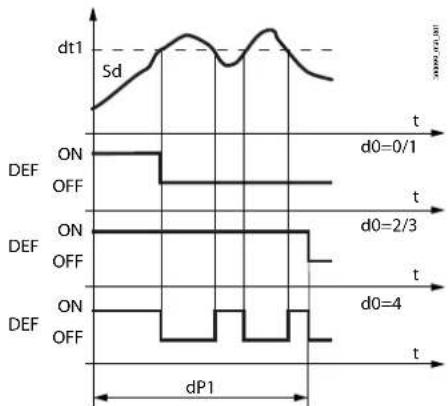
line
| Time | Signal | Duration | |------|--------|----------| | t0 | ON | 0/1 | | t0 | OFF | 0/1 | | t0 | ON | 2/3 | | t0 | OFF | 2/3 | | t0 | ON | 4 | | t0 | OFF | 4 |Ref. Description
| t | Time |
| dt1 | End defrost temperature |
| dP1 | Maximum defrost duration |
| Sd | Defrost probe |
| DEF | Defrost |
Fig. 8.g
The heater defrost by time with temperature control (d0=4) activates the defrost output only if the evaporator temperature (Sd) is less than the value of parameter dt1, and ends after the time defined by dP1. This function is useful for energy saving and to prevent excessive temperatures on the evaporator.
8.3.2 Heater defrost (d0 = 0, 2, 4): duty cycle
The duty cycle refers to the default values of parameters F2 and F3. The electronic valve can be opened to the initial value set for cP1 for a period equal to Pdd.
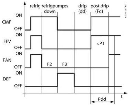
Ref. Description
| t Time | |
| FANFan | |
| DEF Defrost | |
| drip Dripping | |
| CMP Compressor | |
| EEV Electronic expansion valve | |
| Pdd Valve position maintenance time after defrost | |
| Post drip Post-dripping | |
The pump down phase is the period in which the evaporator is emptied of liquid refrigerant, and can be disabled by setting PDt=0.
Fig. 8.h
Operation of the fan during the pump down phase depends on parameters F2 and F3.
During the dripping phase the fan is always off, while during the post-dripping phase operation depends on the setting of parameter Fpd.
| Code | Description | Def. | Min | Max | UOM | User | User term. |
| dd | Dripping time after defrost (fans off): 0 = no dripping | 2 | 0 | 15 | min | M, S | No |
| PDt | Type of pump down (0=none, 1=stop) | 0 | 0 | 1 | - | M | No |
| CPt | Maximum pump down time | 30 | 0 | 60 | s | M, S | No |
| F2 | Evaporator fans with compressor off: 0 = see F0; 1 = always off | 1 | 0 | 1 | - | M, S, U | No |
| F3 | Evaporator fans during defrost: 0=on, 1=off | 1 | 0 | 1 | - | M, S | No |
| Fd | Post-dripping time after defrost (fans off with control active) | 2 | 0 | 15 | min | M | No |
| cP1 | Initial valve position when control starts | 30 | 0 | 100 | % | M, S | No |
| Pdd | Initial valve position maintenance time after defrost | 0 | 0 | 30 | min | M, S | No |
| dSb | Valve position during defrost0: as defined by the type of defrost1: forced closed2 to 100: opening percentage | 0 0 | 100 | % | M, S | No |
Tab. 8.ax
8.3.3 Hot gas defrost (d0=1, 3)
Heosone can manage defrosts by installing a hot gas injection solenoid valve.
This type of defrost can be controlled in two ways:
• Hot gas by temperature (d0=1);
• Hot gas by time (d0 = 3).
In the first case, the defrost ends when reaching the temperature set for parameter dt1 (end defrost threshold (read by Sd)). In the second case, the defrost ends after a set time (parameter dP1 = maximum defrost duration).
Notice: parameter dP1 is also taken into account when end defrost by temperature is selected. If the threshold dt1 is not reached, the defrost will end after the maximum duration (dP1).
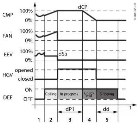
line
| Signal | Time | Value | |--------|------|-------| | CMP | 1 | 100% | | FAN | 2 | 100% | | EEV | 3 | 100% | | HGV | 4 | 100% | | DEF | 5 | 100% |Fig. 8.i
The hot gas defrost algorithm is summarised as follows:
- When there is a defrost request (2), the compressor increases speed linearly reaching the value defined by parameter dCP;
- When the speed defined by dCP has been reached, defrosting (3) starts: the hot gas injection solenoid valve (HGV) is opened (simultaneously bypassing the condenser), the electronic valve (EEV) is closed and the condenser fans are switched off.
- When the maximum time (dP1) and/or the end defrost temperature threshold (dt1) is reached, the compressor begins to decrease speed linearly until stopping. In this phase (4), the hot gas injection solenoid valve (HGV) remains open, and only closed when the compressor stops; this reduces the pressure differential across the compressor, thus facilitating its subsequent restart. The fans remain off and the electronic valve remains closed (opening = 0%);
- The dripping phase (5) then begins, for the duration defined by parameter dd. During this phase the compressor and fans are off, the electronic valve and the hot gas solenoid valve (HGV) remain closed.
When the defrost ends, control resumes.
Notice:
- for MT showcases, a post-dripping phase can also be included, during which the compressor and condenser fan are started, while the evaporator fan remains off;
- Heosone also provides an output for managing condensate drain heaters (parameter DOP). These heaters can be activated with a set delay from when defrost starts (parameter dPt).
The hot gas defrost configuration parameters are summarised in the following table.
| Code | Description | Def. | Min | Max | UOM | User | User term. |
| dCP | Compressor activation percentage during hot gas defrost | 50 | 0 | 100 | % | M, S | No |
| dSa | Valve position at start defrost(0=automatic, 1=closed, 2-100=opening percentage) | 0 0 100 | % | M | No | ||
| dVp | Electronic valve: pre-opening for pressure equalisation after defrost | 100 | 0 | 100 | % | M | No |
| dVt | Electronic valve pre-opening time to equalise the pressure after defrosting | 60 | 0 | 999 | s | M | No |
| drd | Control valve activation delay after starting the compressor when defrost ends | 180 | 0 | 999 | s | M | No |
| dPt | Drain heater activation delay after start defrost | 180 | 0 | 999 | s | M | No |
| CSS | Compressor start-up speed | 50 | - | - | rps | M | No |
| DOAA | Assign hot gas injection solenoid digital output0 = Function disabled1 = NO12 = NO23 = NO3 | 0 | 0 | 3 | - | M | No |
Tab. 8.ay
8.3.4 Advanced parameters
Maximum interval between consecutive defrosts (dl, d1s)
Parameter dl is a safety parameter used to perform cyclical defrosts every "dl" hours. It is also useful if the LAN or RS485 serial network is disconnected. At the start of each defrost, irrespective of the duration, an interval starts being counted. If this interval exceeds dl without a defrost being performed, one is started automatically. The count is always active even if the controller is OFF.
| Code | Description | Def. | Min | Max | UOM | User | User term. |
| dl | Maximum interval between consecutive defrosts | 8 | 0 | 240 | h | M, S, U | Yes |
Tab. 8.az
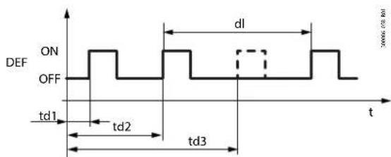
Fig. 8.j
| Ref. | Description |
| dl | Maximum interval between consecutive defrosts |
| td1...td3 | Scheduled defrosts |
| t | Time |
| DEF | Defrost |
Staggered defrosts
The function is used to perform a series of daily defrosts by setting just the first using parameter td1 and then indicating the number of defrosts per day using parameter d1S. The controller automatically schedules all the defrosts to be performed at regular intervals over the 24 hours following the event defined by td1. The same applies to td2 and d52.
| Code | Description | Def. | Min | Max | UOM | User | User term. |
| d1S | Number of daily defrosts (td1)0 = Disabled 5 = 4 hours and 48 minutes 10 = 2 hours and 24minutes 12 = 24 hours and 0 minutes 6 = 4 hours and 0 minutes 11 = 2 hours and 11minutes 23 = 12 hours and 0 minutes 7 = 3 hours and 26 minutes 12 = 2 hours and 0minutes 34 = 8 hours and 0 minutes 8 = 3 hours and 0 minutes 13 = 1 hour and 0 minutes4 = 6 hours and 0 minutes 9 = 2 hours and 40 minutes 14 = 30 minutes | 0 | 0 14 - M, S | No | |||
Tab. 8.ba
Remember that the sub-parameter "d_" of td1 (td2) defines the defrost day, as follows:
d_ = Defrost - day
| 0 = event disabled | 9 = from Monday to Saturday |
| 1 to 7 = Monday to Sunday | 10 = Saturday & Sunday |
| 8 = Monday to Friday | 11 = every day |
Notice:
- if event td1 includes a series of days, the programming always ends at 24.00 on the last day. If event td1 includes one day only, the programming ends at 24.00 on the same day;
- if both td1 and td2 are set, when the defrost events overlap, only the sequence of defrosts that start first are performed...
End defrost by timeout signal (par. r3)
For defrosts that end by temperature (d0=0), this enables the end defrost by timeout signals Ed1 and Ed2.
| Code | Description | Def. | Min | Max | UOM | User | User term. |
| r3 | End defrost signal by timeout: 0=disabled, 1=enabled | 0 | 0 | 1 | - | M | No |
Tab. 8.bb
Defrost at power on (par. d4)
The defrost request at power on has priority over the control request and activation of the continuous cycle.
| Code | Description | Def. | Min | Max | UOM | User | User term. |
| d4 | Defrost at power onFALSE = disabled; TRUE = enabled | 0 | 0 | 1 | M, S | No |
Tab. 8.bc
Defrost delay at power on (parameter d5)
Also active when d4=0. If the digital input is set to enable or start a defrost from an external contact, parameter d5 represents the delay between when the defrost is enabled or called, and when it effectively starts.
| Code | Description | Def. | Min | Max | UOM | User | User term. |
| d5 | Defrost delay at power on0 = delay disabled | 0 0 240 | min | M, S | No |
Tab. 8.bd
Dripping time after defrost (par. dd)
This parameter is the time that the compressor and the evaporator fans stop following a defrost so as to allow the evaporator to drip. If dd=0 no dripping time is enabled, and at the end of the defrost control resumes immediately, without stopping the compressor and the fan, if active.
| Code | Description | Def. | Min | Max | UOM | User | User term. |
| dd | Dripping time after defrost (fans off)0 = no dripping | 2 0 15 min | M, S | No | |||
Tab. 8.be
Valve positioning during defrost (par. dSb)
A fixed position (as a percentage) can be set for valve opening throughout the defrost procedure, from the end of pump-down to the start of the dripping phase. The valve will behave as defined by parameters cP1 and Pdd starting from the post-dripping phase. The opening percentage is applied in all the types of defrost. The function is activated by setting parameter dSb to a value between 1 and 100; this value indicates the position of the valve as a % of the number of steps (not capacity).
Setting the parameter to 1, the valve is closed completely during defrost. Setting the parameter to 0, positioning is disabled and the valve will behave as defined for the type of defrost selected.
| Code | Description | Def. | Min | Max | UOM | User | User term. |
| d5b Va | we position during defrost0: as defined by the type of defrost1: forced closed2 to 100: opening percentage | 0 0 100 | % M, S | No |
Tab. 8.bf
Running time defrost (par.d10, d11)
Running time is a function that determines when the refrigeration unit needs defrosting. In particular, it is assumed that if the evaporator temperature measured by probe Sd remains continuously below a certain set threshold (d11) for a certain time (d10), the evaporator may be frozen and a defrost is activated. The time is reset if the temperature returns above the threshold.
| Code | Description | Def. | Min | Max | UOM | User | User term. |
| dt1 | End defrost temperature (read by Sd) | 8 | -50 | 50 | °C (°F) | M, S, U | Yes |
| dt2 | End defrost temperature (read by Sd2) | 8 | -50 | 50 | °C (°F) | M, S | No |
| d10 | Defrost time in running time mode 0 = function disabled | 0 | 0 | 240 | min | M, S | No |
| d11 | Defrost temperature threshold in running time mode | -30 | -50 | 50 | °C (°F) | M, S | No |
Tab. 8.bg

Fig. 8.k
| Ref. | Description |
| Sd | Defrost probe |
| DEF | Defrost |
| t | time |
Sequential stops (par.dS1, dS2)
Sequential stop mode is especially useful for medium temperature refrigeration units, is based on the intelligent stopping of control to allow the evaporator to defrost naturally by the flow of ambient air only, without activating the defrost output. If the function is enabled (parameter dS1>0), two countdowns are activated during normal control:
• OFFTIME: counts down during the stop time and on hold during control;
• ONTIME: counts down during control and on hold during the stop time.
Two events may occur, with reference to the following figure:
- OFFTIME is reset (instant C): OFFTIME and ONTIME are reset with the values dS1 and dS2 and the defrost is considered completed. Control resumes;
- ONTIME is reset (instant A): OFFTIME is reset with the default value and the natural defrost starts, lasting the entire time dS1. At the end of the defrost (instant B), OFFTIME and ONTIME are reset with the values dS1 and dS2 and control resumes.

line
| Signal | Time Interval | Condition | Value | | :--- | :--- | :--- | :--- | | OFF | 1 | CMP | ON | | OFF | 1 | OFF | OFF | | OFF | C | CMP | ON | | OFF | C | OFF | OFF | | OFF | t | OFF | Off | | OFF | t | OFF | Off | | OFF | t | OFF | Off | | OFF | t | OFF | Off | | OFF | t | OFF | Off | | OFF | t | OFF | Off | | OFF | t | OFF | Off | | OFF | t | OFF | Off | | OFF | t | OFF | Off | | OFF | t | OFF | Off | | OFF | t | OFF | Off | | OFF | t | OFF | Off |Ref. Description
| CMP Compressor | |
| t | time |
Fig. 8.1
| Code | Description | Def. | Min | Max | UOM | User | User term. |
| dS1 | Compressor off time in sequential stop defrost mode0 = function disabled | 0 0 45 | min | M | No | ||
| dS2 | Compressor operating time in sequential stop defrost mode | 120 | 0 | 240 | min | M | No |
Tab. 8.bh
The purpose is to stop control and allow natural defrosts only when necessary. When control stops in sequential stop mode, the defrost icon will come on, the defrost status will be sent to the supervisor and the display will reflect the setting of parameter d6.
Notice: the setting of parameter F3 has no effect. Evaporator fan management depends on parameter F0.
Skip defrost (par. d7, dn)
This function applies to defrosts that end by temperature, otherwise it has no effect. The skip defrost function evaluates whether the defrost duration is less than a certain threshold dn1 (dn2) and based on this establishes whether the subsequent defrosts will be performed or skipped.
| Code | Description | Def. | Min | Max | UOM | User | User term. |
| dP1 | Maximum defrost duration 45 1 240 min M, S, U Yes | ||||||
| dP2 | Max secondary evap. defrost duration 45 1 240 min M, S No | ||||||
| d7 | Skip defrost: 0=disabled, 1=enabled | 0 | 0 | 1 | - | M, S | No |
| dn | Nominal skip defrost duration | 75 | 0 | 100 | % | M, S | No |
Tab. 8.bi
Thresholds dn1 (evaporator 1) and dn2 (evaporator 2) are defined by:
$$ d n 1 = \frac {d n}{1 0 0} \cdot d P 1, d n 2 = \frac {d n}{1 0 0} \cdot d P 2 $$
The algorithm keeps a counter of the defrosts to be skipped:
- if the defrost ends in a time less than dn1, the counter of the defrosts to be skipped is increased by 1;
- if the defrost ends normally, the next defrost is performed;
- when the counter reaches 3, three defrosts are skipped and then the counter is reset to 1;
- at power on, the defrost is performed 7 times without increasing the counter, from the eighth on the counter is updated.
Notice: in power defrost mode, the maximum defrost durations dP1 and dP2 are increased by the value of parameter ddP.
Power defrost (par. ddt, ddP)
Power defrost is used to increase the end defrost threshold dt1 (dt2 for the second evaporator) and/or the maximum defrost duration dP1 (dP2 for the second evaporator). These increases allow more effective defrosts. Power defrosts are performed on each defrost call during night status or when suitably configured by the RTC parameters (sub-parameter P of parameters td1 to td8), so as to allow the user to choose the conditions that are most suitable for this special procedure. Power defrost is activated when at least one of the increases, ddt or ddP, has any value other than zero.
| Code | Description | Def. | Min | Max | UOM | User | User term. |
| ddt | Additional end defrost temperature delta in power defrost mode | 0 | -20 | 20 | °C (°F) | M, S | No |
| ddP | Additional maximum defrost time delta in power defrost mode | 0 | 0 | 60 | min | M, S | No |
| td1..8-P | Defrost 1 to δ - enable power defrost: 0= normal, 1= power defrost | 0 | 0 | 1 | - | M, S, U | No |
Tab. 8.bj
8.4 Evaporator fans
The evaporator fans can be managed, if required, according to the temperature measured by any two of the probes connected to the Heosone controller. The deactivation threshold is equal to the value of parameter F1, and the hysteresis is equal to the value of Frd.
Notice: during the dripping time, the evaporator fans are always off, while during the post-dripping time, if set, evaporator fan operation depends on the setting of par. Fpd.
Fixed-speed fans
The parameters used to manage fixed-speed fans are shown below.
Heosone manages the evaporator fans as follows:
- F0 = 0 always on;
- F0 = 1 off when the difference between the two probe values Sa and Sb (defined by parameters FSa and FSb) exceeds the threshold set for parameter F1;
- F0 = 2 on/off based on Sa probe, defined by parameter FSa.
| Code | Description | Def. | Min | Max | UOM | User | User term. | |
| F0 Evaporator fan management0 = always on1 = activation based on Sa - Sb (see FSa and FSb)2 = activation based on Sa(Sa = first probe, Sb = second probe) | 0 | 0 | 2 | - | M , | S , U N o | ||
| F1 Evaporator fan activation threshold (only if F0 = 1 or 2) -5 -50 50 °C (°F) M, S, U No | ||||||||
| Frd | Fan activation differential (including variable speed) | 2 | 0.1 | 20 | °C (°F) | M, S | No | |
| FSa | First fan control probe | 2 | 0 | 14 | - | M, S | No | |
| 0 : Not configured | 8 : Auxiliary 2 (Saux2) | |||||||
| 1 : Outlet (Sm) | 9 : Ambient (SA) | |||||||
| 2 : Defrost (Sd) | 10 : Room humidity (SU) | |||||||
| 3 : Intake (Sr) | 11 : Glass temperature (Svt) | |||||||
| 4 : Superheated gas (tGS) | 12 : Dew point (SdP) | |||||||
| 5 : Saturated evaporation pressure (PEu) | 13 : Virtual probe (Sv) | |||||||
| 6 : Defrost 2 (Sd2) | 14 : Saturated evaporation temperature (tEu) | |||||||
| 7 : Auxiliary 1 (Saux1) | ||||||||
| FSb | Second fan control probe - see FSa | 13 | 0 | 14 | - | M, S | No | |
Tab. 8.bk

Ref. Description
| Sa | Probe set by parameter FSa |
| Sb | Probe set by parameter FSb |
| F1 | Fan activation threshold |
| Frd | Differential |
| t | Time |
| FAN | Evaporator fans |
Fig. 8.m
The fans can be turned off in the following situations:
- when the compressor is off (parameter F2);
• during defrosts (parameter F3).
During the dripping time (parameter dd > 0) the fans are off, and during the post-dripping time (parameter Fd > 0), the evaporator fans are on or off depending on the value of parameter Fpd.
This is useful to allow the evaporator to return to temperature after defrosting, thus avoiding blowing warm hot and moist air into the refrigerated environment.
The evaporator fans can be forced on during control (parameter F2) and during defrosts (parameter F3).
| Code | Description | Def. | Min | Max | UOM | User | User term. |
| dd | Dripping time after defrost (fans off): 0 = no dripping | 2 | 0 | 15 | min | M, S | No |
| F2 | Evaporator fans with compressor off:0 = see F0; 1 = always off | 1 | 0 | 1 | - | M , | S , |
| F3 | Evaporator fans during defrost: 0=on, 1=off | 1 | 0 | 1 | - | M, S | No |
| Fd | Post-dripping time after defrost (fans off with control active) | 2 | 0 | 15 | min | M | No |
| Fpd | Evaporator fans during post-dripping: 0=on, 1=off | 1 | 0 | 1 | - | M | No |
Tab. 8.bl
Variable-speed fans (EC fans)
The installation of variable-speed fans may be useful in optimising energy consumption. In this case, the fans are powered by the mains, while the control signal may come via output Y1 or Y2.
The maximum and minimum fan speed can be set using advanced parameters F6 and F7.
If using the fan speed controller, F5 represents the temperature below which the fans are activated. There is a fixed hysteresis of 1^ C for deactivation.
Code Description
Def. Min Max UOM User User term.
| F5 Evap. fan cut-off temperature (hyst. 1°C) 50 F1 50 °C (°F) M, S No |
Tab. 8.bm
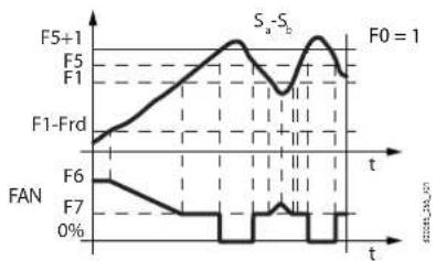

line
| Metric | Value | |--------|-------| | F5+1 | 0% | | F5 | 0% | | F1 | 0% | | F1-Frd | 0% | | F6 | 0% | | F7 | 0% | | S₄ | 0% | | F0 | 2% |Ref. Description
| Sa Probe set by parameter FSa | |
| Sb Probe set by parameter FSb | |
| Frd Differential | |
| t | Time |
| F5 Fan cut-off temperature | |
| F1 Fan activation threshold | |
| FAN Evaporator fans | |
Fig. 8.n
The advanced parameters for the evaporator fans concern the minimum and maximum speed and the peak time.
Code Description
Def. Min Max UOM User User term.
| F6 Max evaporator fan speed | 23 F7 100% M, S | No | |||||
| F7 | Min evaporator fan speed | 15 | 0 | F6 | % | M, S | No |
| F8 Evaporator fan peak time0 = Function disabled | 0 | 0 | 240 | s | M, S | No | |
| F10 | Evaporator fan forcing time at max speed0 = Function disabled | 0 | 0 | 240 | min | M, S | No |
Tab. 8.bn
F6: is the maximum fan speed, expressed as a % of the output. For 0 to 10 V outputs, it represents the output voltage at maximum speed as a percentage. The same is true for the minimum speed set for F7.
The fan peak time F8 represents the operating time at maximum speed set using parameter F6 to overcome the mechanical inertia of the motor.
F10 represents the frequency at which the fan is operated at maximum speed for the peak time (F8). If the fan operates too long at low speed, ice may form on the blades; to avoid this, at intervals of every F10 minutes, the fan is switched on at maximum speed for the time set for parameter F8.

line
| Time (T) | FAN SPEED | F1-Frd | | :--- | :--- | :--- | | 0 | F6 | | | 1 | F7 | | | 2 | F1 | | | 3 | F5 | | | 4 | F5+1 | || Ref. | Description |
| T | temperature |
| F1 | Fan activation threshold |
| Frd | Differential |
| F5 | Fan cut-off temperature |
| F6 | Maximum speed |
| F7 | Minimum speed |
Fig. 8.0
8.5 Condenser fans
The condensing temperature can be controlled either using modulating fans (0-10 V or PWM control signal) or ON/OFF fans. The configuration is selected as follows:
- ON/OFF: by selecting the corresponding digital output (parameter DOt) and setting the minimum request threshold for activation (parameter FCL)
- 0-10 V: by selecting the modulating output (parameter /AE), for setting the digital output (parameter DOt) and setting the minimum request threshold for activation (parameter FCL, typically set to the minimum fan activation percentage) and the maximum request threshold (FCH parameter)
- PWM: by configuring parameter PWM1_Type and/or PWM2_Type
| Code | Description | Def. | Min | Max | UOM | User | User term. |
| /AE Assign | channel for modulating condensing fan output0 = not configured1 = Y12 = Y2 | 0 | 0 | 2 | - | M | , S |
| Dot Assign | channel for condensing fan digital output0 = not configured1 = NO12 = NO23 = NO3 | - | - | - | - | M,S | No |
| FCL Minimum | condensing fan speed, expressed as a percentage of the maximum speed PWM1_Max | 10 0 | FCM % | M,S | No | ||
| PWM1_Type | Type of fan associated with output PWM1 (J4):0: none1: evaporator fan2: condenser fan | 0 | 0 | 2 | - | M | , S |
| PWM2_Type | Type of fan associated with output PWM2 (J3):0: none1: evaporator fan2: condenser fan | 0 | 0 | 2 | - | M | , S |
Tab. 8.bo
Parameter CFd sets the control mode, choosing between:
- Proportional + integral control (P+I) as a function of the condensing temperature (Sc)
• Function of the compressor rotation speed (cs)
| Code | Description | Def. | Min | Max | UOM | User | User term. |
| CFd | Condensing fan control mode(TRUE = control based on condensing temperature probe,FALSE = control based on compressor speed) | TRUE | - | - | - | M | No |
Tab. 8.bp
For control based on the condensing temperature, parameters Cts, CF0, CF1 can be adjusted to improve system stability.
| Code | Description | Def. | Min | Max | UOM | User | User term. |
| CF0 | Proportional gain for condensing fan control | 5 | - | - | - | M, S | No |
| CF1 | Integral time for condensing fan control | 70 | - | - | s | M, S | No |
| CtS | Condensing temperature set point | 0 | - | - | °C (°F) | M, S | No |
Tab. 8.bq
If, on the other hand, fan speed modulation depends on the compressor activation percentage, control will follow the trend shown in the graph (Fig. 8.p).

line
| Comp (rps) | Condenser fans request (%) | | ---------- | -------------------------- | | FCI | 0 | | FCd | 75 | | CSM | 100 |Fig. 8.p
| Code | Description | Def. | Min | Max | UOM | User | User term. |
| CSM | Maximum compressor activation speed (custom) | 90 | - | - | rps | M | No |
| FCI | Minimum compressor activation speed (custom) | 20 | - | - | rps | M | No |
| FCd | Intermediate compressor activation speed (custom) | 45 | FCI | CSM | rps | M | No |
| FCH | Maximum condensing fan speed, expressed as a percentage of maximum speed PWM1_Max | 19 | FCM | 100 (*) | % | M | No |
| FCL | Minimum condensing fan speed, expressed as a percentage of maximum speed PWM1_Max | 10 | 0 | FCM | % | M | No |
| FCM | Intermediate condensing fan speed, expressed as a percentage of maximum speed PWM1_Max | 15 | FCL | FCM | % | M | No |
| PWM1_Max | Maximum condensing fan speed (with PWM signal) | 1800 | 0 | 1800 | rpm | M | No |
Tab. 8.br
(*) valid only when auto-tuning is enabled
Notice: For the configuration with ON/OFF fans, the output set for Dot will be activated when the request as a percentage exceeds the threshold FCL, and then deactivated when the request falls to 0%.

line
| Condenser fans request (%) | DDo | |---|---| | 0 | 0 | | FCL 100 | 0 |Fig. 8.q
8.5.5 EC fan calibration (auto-tuning): introduction
If managing external fans via a 0-10 V analogue output (Y1, Y2), auto-tuning, even if enabled, will have no impact on fan management.
Auto-tuning only applies to integrated fan management, i.e. the fan is directly connected to outputs J3/J4.
In this case, in order to ensure precise control of fan motor speed, it is recommended to complete the calibration procedure before starting the unit.
This procedure will allow a precise relationship to be defined between the signal sent by the controller and the required fan rotation speed.
The calibration procedure (auto-tuning), if enabled by setting parameter FAT=1, will start whenever the controller is switched on.
Caution:
auto-tuning is disabled by default (FAT=0). In this case, the percentage defined by parameters FCH, FCM and FCL refers to the maximum output voltage that can be supplied by the inverter.
The values of FCH / FCM / FCL are limited, by default, to 19 / 15 / 10% respectively: this avoids delivering an output voltage signal that could damage the fans' electronic circuits.
The optimum values of FCH, FCM and FCL for controlling the fans need to be defined by testing in the laboratory, as they are closely related to both the motor and the blades used.
Caution:
the use of a fan motor compatible with the those proposed by Carel requires compliance with the electrical specifications shown under "Technical specifications". The auto-tuning procedure requires tachometer feedback in order to correctly determine the fan rotation speed. It should also be noted that the tachometer must return an output signal with 12 pulses per rotation.
EC fan calibration procedure (FAT=1)
If wanting to use the auto-tuning procedure (FAT=1), the default values of parameters FCH, FCM and FCL need to be modified: the best values for correctly tuning the fan operating curve are 100, 75 and 50% respectively. Subsequently, power off the controller, wait a few seconds and then power on again to start the calibration procedure.
Caution:
if subsequently disabling auto-tuning (FAT=0), make sure parameters FCH, FCM, FCL are restored to the default values.
The auto-tuning procedure involves two phases:
• PHASE 1: maximum PWM signal calibration
In this phase, the fan speed is slowly increased until reaching the maximum speed defined by parameter PWM1_Max (e.g. 1800 rpm), allowing the controller to internally calibrate the maximum signal that can be provided. Once the maximum signal is identified, the fan is stopped and the calibration procedure goes to phase 2.
- PHASE 2: PWM signal calibration across the range of modulation
As the relationship between the PWM signal sent and the fan rotation speed is not linear, intermediate calibration points need to be defined in order to allow a precise relationship between required speed and the actual speed.
The fan speed is slowly increased until reaching the maximum speed defined by parameter PWM1_Max (e.g. 1800 rpm) and, at the speeds defined by parameters FCL, FCM and FCH, the controller internally records the associated signal value. Once the maximum speed is reached (PWM1_Max), the calibration procedure ends.
| Code | Description | Def. | Min | Max | UOM | User | User term. |
| FAT | Enable calibration procedure (auto-tuning) at start-up | No | No | Yes | - | M | No |
| FCH | Maximum condensing fan speed, expressed as a percentage of maximum speed PWM1_Max | 19 | FCM | 100 | % | M | No |
| FCL | Minimum condensing fan speed, expressed as a percentage of maximum speed PWM1_Max | 10 | 0 | FCM | % | M | No |
| FCM | Intermediate condensing fan speed, expressed as a percentage of maximum speed PWM1_Max | 15 | FCL | FCM | % | M | No |
| PWM1_Max | Maximum condensing fan speed (with PWM signal) | 1800 | 0 | 1800 | rpm | M | No |
Tab. 8.bs
8.6 Anti-sweat heater or fan modulation
The control of anti-sweat heaters is performed by comparing the dew point calculated based on the ambient temperature and humidity, and the temperature of the showcase glass, measured by a probe or estimated using the showcase outlet, intake and ambient temperature. Heosone features two types of anti-sweat heater control:
• PI (proportional, integral);
- fixed activation (manual control).
The conditions for the activation of the algorithms are as follows:
Algorithm Activation condition
| PI rHd>0 | |
| fixed activation (manual control) rHd = 0; rHt >0 |
If the temperature read by the glass temperature probe is only estimated, PI control becomes proportional only. If both algorithms are activated, the PI algorithm has priority over fixed activation, which does not require the ambient temperature and humidity probes. There are a series of conditions whereby the PI algorithm stops operating and, if enabled, fixed activation control takes over.
Condition Cause
| Glass temperature probe not valid | physical probe not configured or faulty;the estimated glass temperature probe value cannot be used as the outlet probe or intake probe is not configured or is faulty or the ambient probe is broken or absent (*) |
| Dew point not valid humidity | dity probe and ambient temperature probe are both not configured or not working;the serial dew point value is not available |
(*) If the intake probe is not configured or is faulty, only the outlet probe is used.
PI control
Inputs
The humidity (SU) and ambient temperature (SA) probes may be (see parameters /FL, /FI):
- connected locally to each controller;
- sent from the supervisor via the serial probes.
Alternatively, the supervisor can directly supply the dew point value (Sdp) using the serial probes (see parameter /Fn). The glass temperature probe (Svt) can be connected directly to each controller (see parameter /FM), or the value can be estimated. The estimate of the glass temperature probe reading is performed internally when: ambient temperature (SA), outlet temperature (Sm) and intake temperature (Sr) are available, and depends on parameters rHA, rHb and rHS. Parameters rHo, rHd and rHL determine the modulating output.
Code Description
Def. Min Max UOM User User term.
| rHS | Virtual probe composition for glass temp. probe estimate0 = Outlet probe Sm100 = Intake probe Sr | 20 | 0 | 100 | % | M | No |
| rHA | Coeff. A for glass temp. probe estimate | 2 | -20 | 20 | °C (°F) | M | No |
| rHb | Coeff. B for glass temp. probe estimate | 22 | 0 | 100 | - | M | No |
| rHo | Offset for anti-sweat modulation | 2 | -20 | 20 | °C (°F) | M | No |
| rHd | Differential for anti-sweat heater modulation | 0 | 0 | 20 | °C (°F) | M | No |
Tab. 8.bt
If one of the probes is not available (SA or either Sm or Sr), only fixed activation control will be possible, according to parameters rHu and rHt.
Outputs
The percentage of activation (OUT) for anti-sweat heater control depends on the difference between the dew point calculated and the value read by the glass temperature probe, the value of parameter rHo (offset) and the value of parameter rHd (differential), as shown in the following figure. The CUTOFF is a constant of 5°C and the hysteresis is 1°C.

line
| Svt | OUT | | ------- | ----- | | Sdp | 0% | | rHo | 0% | | rHd | 0% | | CUTOFF | 1°C |Fig. 8.r
Ref. Description
| SdP | Dew point |
| rHo | Offset for anti-sweat modulation |
| rHd | Diff. for anti-sweat heater modulation |
| OUT | Anti-sweat control |
| Svt | Glass temperature probe |
| Min | Minimum fan speed |
| Max | Maximum fan speed |
Min: fixed minimum output of 10%; Max: fixed maximum output of 100%.
The action is proportional only if the estimate of the glass temperature is used, and proportional and integral (Tint=240 s, constant) if the actual glass temperature probe is us. The aim of the integral action is to bring the glass temperature towards the set point (Sdp+rHo).
Caution: if the serial probes from the supervisor are used for sending the ambient temperature and humidity values, Heosone has four auxiliary variables that save the last useful value available for 30 minutes. This may be useful in the event of a supervisor power failure.
Alarms due to probes without updated values are therefore normally shown on start-up, when these variables have not yet been initialised.
Fixed activation control (manual control)
Control depends only on parameters rHu and rHt and follows the trend shown in the figure.
| Code | Description | Def. | Min | Max | UOM | User | User term. |
| rHu Manual anti-sweat heater activation percentage (of period "rHt") | 70 0 100 | % M | No | ||||
| 0 = function disabled | |||||||
| rHt Manual anti-sweat heater activation period | 5 0 180 | min | M No | ||||
| 0 = function disabled | |||||||
Tab. 8.bu
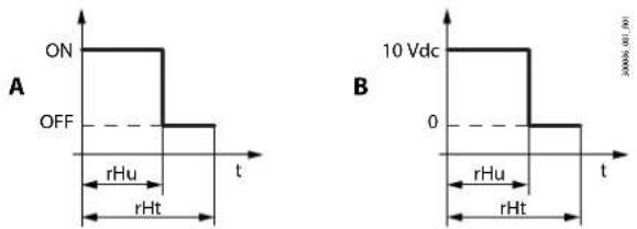
line
| Chart | Time (t) | Voltage (Vdc) | |-------|----------|---------------| | A | ON | ON | | A | OFF | OFF | | B | t | 10 Vdc | | B | t | 0 |Fig. 8.s
Ref. Description
| A | Relay output |
| B | 0-10 Vdc output |
| rHu | Anti-sweat heater activation percentage |
| rHt Manual | anti-sweat heater activation period |
| t | Time |
8.7 Electronic valve
8.7.1 Introduction
Heosone features a built-in driver for managing an electronic expansion valve. This can be enabled by appropriately setting parameter P1.
| Code Description | Def. | Min | Max | UOM | User | User term. |
| P1 Electronic valve: 0 = not present; 1 = OnBoard driver 1 0 1 - M Yes |
Heosone has been designed to manage one electronic expansion valve on one evaporator.
Notice: CAREL suggests using ratiometric probes to read the evaporation pressure, which is automatically converted to saturated temperature based on specific tables for the type of refrigerant used.
Description of operation
The following values are used to calculate superheat:
tGS = superheated gas temperature;
tEu = saturated evaporation temperature, converted from the pressure.
Superheat is calculated based on these values:
SH = tGS - tEu.
Heosone modulates the opening of the electronic expansion valve opening, thus controlling refrigerant flow inside the evaporator, so as to maintain the superheat value near the corresponding set point P3. The opening of the valve is controlled independently of normal temperature control. When there is a cooling request (the compressor/solenoid valve relay is activated), control of the electronic valve is also activated. If the superheat value read by the probes is greater than the set point, the valve is opened proportionally to the difference between the values. The speed of variation and the percentage of opening depend on the PID parameters set. Opening is continuously modulated based on the superheat value, with PID control.
Notice: all the references relating to control of the electronic valve are based on the use of a CAREL E2V electronic expansion valve. The descriptions therefore consider the steps of the stepper motor used for this type of valve, for example, the maximum number of opening steps is 480.
Superheat set point (parameter P3)
The parameter that electronic valve control is based on is superheat, which effectively tells whether or not there is liquid at the evaporator outlet. Superheat is calculated as the difference between: superheated gas temperature (measured by a temperature sensor located at the end of the outlet tGS) and the saturated evaporation temperature (calculated based on the reading of a pressure transducer located at the evaporator outlet (PEu/tEu) and using the Tsat(P) conversion curve for each refrigerant)
| Code | Description | Def. | Min | Max | UOM | User | User term. |
| P3 | Superheat set point | 10 | 25 K M, S, U | Yes |
SH = tGS - tEu
SH = superheat (K)
tGS = superheated gas temperature (°C/°F);
tEu = saturated evaporation temperature, converted from the pressure (°C/°F).
If superheat is high it means that the evaporation process is completed well before the evaporator outlet, and therefore flow-rate of refrigerant through the valve is insufficient. This causes a reduction in cooling efficiency due to the failure to exploit part of the evaporator.
The valve must therefore be opened further. Vice-versa, if superheat is low it means that the evaporation process has not concluded before the end of the evaporator and a certain quantity of liquid will still be present at the compressor suction port. The valve must therefore be closed further. The superheat working range is limited at the lower end: if the flow-rate through the valve is excessive the superheat measured will be near 0 K.
This indicates the presence of liquid, even if the percentage of this relative to the gas cannot be quantified. There is therefore a risk to the compressor. On the other hand, a high superheat value, as mentioned, corresponds to an insufficient flow-rate of refrigerant. Superheat must therefore always be greater than 0 K and have a minimum stable value allowed by the valve-unit system.
A low superheat value in fact corresponds to a situation of probable instability due to the turbulent evaporation process approaching the measurement point of the probes. The expansion valve must therefore be controlled very precisely and be able to respond promptly around the superheat set point.
Parameters SH, tGS, tEu and PPU (valve opening percentage) are displayed only variables, used to monitor the refrigeration process.
Heosone, with PID control, tends to maintain the actual superheat, calculated based on the probe readings, around the value set for this parameter. This is done by gradually varying the opening of the valve based on the difference between the actual superheat and the set point.
Caution: the measured superheat value depends on the quality of installation, the positioning of the probes and other factors. Depending on the specific installation, the superheat set point may differ from the actual value. Set point values that are too low (2 to 3 K), albeit ideally usable, may cause problems involving the return of liquid refrigerant to the compressor.
Initial valve position when control starts (parameter cP1)
This is used to set the position of the valve as a percentage when control starts. High values ensure intense and immediate cooling of the evaporator when each request is sent, however may cause problems if the valve is oversized with reference to the unit's cooling capacity. Low values, on the other hand, allow a more gradual and slower action.
| Code | Description | Def. | Min | Max | UOM | User | User term. |
| cP1 | Initial valve position when control starts 30 D 100 % M, S No |
Tab. 8.bx
Initial valve position maintenance time after defrost (parameter Pdd)
At the end of a defrost, during the dripping phase, the expansion valve can be forced open to the initial value set for cP1 for a time equal to Pdd. This means greater immunity of the unit to return of liquid due to an excessively high evaporator temperature.
| Code | Description | Def. | Min | Max | UOM | User | User term. |
| Pdd | Initial valve position maintenance time after defrost | 0 | 0 | 30 | min | No |
Tab. 8.by
PID control (parameters P4, P5, P6)
The opening of the electronic valve is controlled based on the difference between the superheat set point and the actual superheat calculated by the probes. The speed of variation, reactivity and the ability to reach the set point depend on three parameters:
• Kp = proportional gain, parameter P4;
• Ti = integral time, parameter P5;
- Td = derivative time, parameter P6.
The ideal values to be set vary depending on the applications and the utilities managed, nonetheless default values are proposed that allow good control in the majority of cases.
For further details, refer to classic PID control theory.
| Code | Description | Def. | Min | Max | UOM | User | User term. |
| P4 | Proportional gain | 150 | 100 - | M | No | ||
| PS | Integral time: 0 = function disabled | 150 | 0 | 900 | s | M | No |
| P6 | Derivative time: 0 = function disabled | 5 | 0 | 100 | s | M | No |
Tab. 8.bz
- P4: this represents the amplification factor. Its action is directly proportional to the variation in superheat. It acts on the speed of the valve, in terms of steps/°C. The valve moves P4 steps for every degree centigrade variation in superheat, opening or closing whenever the superheat value increases or decreases respectively. It also acts on the other control factors, and is valid in both normal control and with all emergency control functions.
High values ==> fast and reactive valve. Low values ==> slow and less reactive valve.
- P5: this represents the time required by the controller to balance the difference between the set point and the actual superheat. In practical terms it limits the number of steps that the valve completes each second. It is only valid during normal control, the special functions in fact have their own integral time. High values ==> slow and less reactive valve (e.g. 400) Low values ==> fast and reactive valve P5 = 0 ==> integral action disabled
- P6: this represents the reaction of the valve to variations in superheat. It amplifies or reduces variations in superheat.
High values ==> rapid variations Low values ==> limited variations P6 = 0 ==> derivative action disabled
8.7.2 Protection functions
LowSH: low superheat threshold (par. P7)
To prevent too low superheat values that may cause the return of liquid to the compressor or system instability (swings), a low superheat threshold can be defined, below which a special protection function is activated. The LowSH threshold must be lower than the superheat set point. When the superheat falls below the threshold, the system immediately enters low superheat status and activates an integral control action, with the aim of closing the electronic valve more quickly. The low superheat integral time indicates the intensity of the reaction: the lower the value, the more intense the reaction will be. If the device remains in low superheat status for a certain period, a low superheat alarm is activated, with the display showing the message "LSH", if enabled. The low superheat signal features automatic reset, when the condition is no longer present or the controller is switched off (standby). When low superheat status is activated, the unit can be switched off (parameter P10).
| Code | Description | Def. | Min | Max | UOM | User | User term. |
| P7 | LowSH: low superheat threshold 2 -10 P3 KM, S No | ||||||
| P8 | LowSH: integral time - 0 = function disabled | 10 | 0 | 240 | s | M | No |
| P9 | LowSH: alarm delay - 0 = alarm disabled | 120 | 0 | 999 | s | M | No |
Tab. 8.ca

Fig. 8.t
| Ref. | Description |
| SH | Superheat |
| LowSH Low | superheat protection |
| ALARM | Alarm |
| P7 | LowSH protection threshold |
| P9 | Alarm delay |
| t | Time |
MOP: Maximum evaporation pressure
When starting or restarting a system, the compressor may not be able to satisfy the cooling demand. This may cause an excessive increase in the evaporation pressure and consequently the corresponding saturated temperature. When the evaporation pressure, expressed in degrees (saturated), rises above the threshold, after a certain settable time the system enters MOP protection status: PID superheat control is stopped and the controller starts gradually closing the valve with an integral action to return the evaporation pressure below the set threshold. The protection function has been designed to allow a gradual return to normal operating conditions, that is, when the critical conditions have ended, the controller temporarily operates with a higher superheat set point until the function is automatically reset.
| Code | Description | Def. | Min | Max | UOM | User | User term. |
| PM1 | MOP: max saturated evap. temp. threshold | 50 | -50 | 50 | °C | M, S | No |
| PM2 | MOP: integral time | 20 | 0 | 800 | s | M | No |
| PM3 | MOP: alarm delay - 0 = function disabled | 240 | 0 | 999 | s | M | No |
| PM4 | MOP: function activation delay when starting control | 2 | 0 | 240 | s | M | No |
| PM6 | MOP: max suction temp. threshold | 50 | -50 | 50 | °C (°F) | M, S | No |
Tab. 8.cb

line
| Time | T_EVAP | PM1 | MOP | OFF | ALARM | |------|--------|-----|-----|-----|-------| | t | ON | Peak| ON | Off | ON | | t | OFF | Peak| Off | Off | Off | | t | PM3 | Peak| PM3 | PM3 | PM3 |Fig. 8.u
| Ref. | Description |
| T_EVAP | Evaporation temperature |
| MOP | MOP protection |
| ALARM | Alarm |
| PM1 | MOP threshold |
| PM3 | Alarm delay |
| t | Time |
PM1 represents the maximum evaporation pressure, expressed in degrees (saturated), above which the MOP protection and alarm are activated (each with its own delay times). There is a gradual return to normal operation, to avoid the critical situations arising again.
PM2 represents the integral time for the maximum evaporation pressure protection
function. This replaces the normal PID control during MOP status.
PM2 = 0 ==> MOP protection and alarm disabled
PM3 represents the alarm activation delay after exceeding the MOP threshold.
When the alarm is activated, the following occur:
- message "MOP" shown on the display
- buzzer activated
The alarm features automatic reset when the evaporation pressure falls below the threshold PM1.
PM4 represents the activation delay MOP protection after the last activation of the solenoid valve.
PM4 = 0 ==> MOP alarm disabled
LSA - Low suction temperature
When the suction temperature falls below the threshold, after the set delay, an alarm is activated that closes the electronic valve. The alarm is reset when the suction temperature exceeds the set threshold plus the hysteresis.
| Code | Description | Def. | Min | Max | UOM | User | User term. |
| P10 | Enable unit shutdown due to low superheat (LSH) and/or low suction temperature (LSA) alarm - 1=enable closing | 0 | 0 | 1 | - | M | S N |
| P11 | LSA: low suction temperature threshold | -35 | -50 | 50 | °C | M, S | No |
| P12 | LSA: alarm delay - 0 = alarm disabled | 120 | 0 | 999 | s | M | No |
Tab. 8.cc
P11 represents the suction temperature below which the alarm is activated, after the corresponding delay.
The threshold for resetting the alarm is this threshold plus 1°C.
P12 represents the alarm activation delay after exceeding the threshold P11.
When the alarm is activated, the following occur:
- message "LSA" shown on the display;
- buzzer activated
P12 = 0 ==> LSA alarm disabled.

line
| Time Segment | Signal | Value | | ------------ | ------ | ----- | | Top Left | T_SUCT | P11+1°C | | Top Right | T_SUCT | P11 | | Bottom Left | LSA | ON | | Bottom Right | LSA | OFF | | Bottom Right | ALARM | ON | | Bottom Right | ALARM | OFF |Fig. 8.v
| Ref. | Description |
| T_SUCT | Suction temperature |
| P11 | LSA: low suction temperature threshold |
| P12 | LSA: alarm delay |
| t | Time |
| LSA | Protection |
LOP Minimum evaporation pressure
This function prevents the evaporation pressure from staying too low for too long. When the evaporation pressure, expressed in degrees (saturated), falls below the threshold, the LOP protection is activated, which adds an integral action to normal PID control, specifically devised to be more reactive as regards the opening of the valve. The PID control remains active, as superheat must continue to be monitored as to avoid flooding the compressor. The LOP alarm is delayed from the activation of the protection function, both are reset automatically when the pressure value, in degrees (saturated), exceeds the threshold.

line
| Time | T_EVAP | PL1 | LOP | OFF | ALARM | |------|--------|-----|-----|-----|-------| | t | High | Low | ON | Off | ON | | t+2.5| Low | Low | ON | Off | ON | | t | High | Low | ON | Off | ON | | t+2.5| High | Low | ON | Off | ON |Fig. 8.w
| Ref. | Description |
| T_EVAP | Evaporation temperature |
| LOP | LOP protection |
| PL3 | LOP: alarm delay |
| t | Time |
| LOP | Protection |
| Code | Description | Def. | Min | Max | UOM | User | User term. |
| PL1 | LOP: min saturated evap. temp. threshold | 50 | -50 | 50 | °C | M, S | No |
| PL2 | LOP: integral time | 10 | 0 | 800 | s | M, S | No |
| PL3 | LOP: alarm delay - 0 = function disabled | 120 | 0 | 240 | s | M, S | No |
Tab. 8.cd
PL1 represents the evaporation pressure, expressed in degrees (saturated), below which the LOP protection is activated. The protection function is deactivated immediately when the pressure exceeds this threshold.
PL2 represents the integral constant used during activation of the LOP protection function. This integral time acts in addition to normal PID control.
PL2 = 0 ==> LOP protection and alarm disabled.
PL3 represents the alarm activation delay after exceeding the LOP threshold. When the alarm is activated, the following occur:
- message "LOP" shown on the display;
- buzzer activated
The alarm features automatic reset when the evaporation pressure rises above the threshold PL1.
PL3 = 0 ==> LOP alarm disabled.
Manual valve positioning
PMP is used to enable/disable manual positioning of the valve.
PMP = 0: manual positioning disabled;
PMP = 1: manual positioning enabled.
If manual positioning is enabled, this is used to set the electronic valve manual opening steps.
| Code | Description | Def. | Min | Max | UOM | User | User term. | |
| PMP | Enable manual expansion valve positioning0=disabled, 1=enabled | 0 | 0 | 1 | - | M | S | N |
| PMu | Manual valve position | 0 | 0 | 480 | steps | M,S | No | |
Tab. 8.ce
Read-only variables
In addition to the parameters specified above, other read-only variables are available for monitoring control of the electronic valve.
| Code | Description |
| PF | Valve opening steps (supervisor) |
| SH | Superheat |
| PPU | Valve opening percentage |
| tGS | Superheated gas temperature |
| tEu | Saturated evaporation temperature |
Tab. 8.cf
PF: status variable that only displays, solely from the supervisor, the current position of the electronic valve calculated by the controller. System malfunctions may cause this value to be different from the effective position of the valve.
SH: status variable that only displays the superheat value calculated by Heosone.
PPu: status variable that only displays the electronic valve opening as a percentage.
tGS: status variable that only displays the evaporator outlet temperature read by the corresponding probe (parameter /Fd).
tEu: status variable that only displays the saturated evaporation temperature calculated by the corresponding evaporation pressure probe or read directly by the NTC probe (parameter /FE).
8.8 Compressor
Heosone features the following compressor protection parameters.
| Code | Description | Def. | Min | Max | UOM | User | User term. |
| d9 | Lost priority over compressor protection times0/1 = protection times observed/protection times not observed | 1 | 0 | 1 | - | M | S N |
| c0 | Delay to enable compressor and evaporator fans at power on | 0 | 0 | 15 | min | M, S | No |
| c1 | Min time between consecutive compressor starts | 360 | 0 | 999 | s | M | No |
| c2 | Min compressor OFF time | 360 | 0 | 999 | s | M | No |
| c3 | Min compressor ON time | 360 | 0 | 999 | s | M | No |
Tab. 8.cg
c0 is used to delay the start of control when the device is powered on. This is useful in the event of power failures, so that the controllers don't all start at the same time, avoiding potential problems of electrical overload.
c1 sets the minimum time between two successive starts of the compressor, irrespective of the request. This parameter can be used to limit the maximum number of starts per hour;
c2 sets the minimum compressor off time. The compressor will not be started again until the minimum time set has elapsed; c3 sets the minimum compressor activation time: the compressor will not be switched off until it has been on for at least the time set for c3;
d9 disables the compressor protection times when defrosting:
d9 = 0: protection times are observed;
d9 = 1: protection times are ignored, defrosting has higher priority.
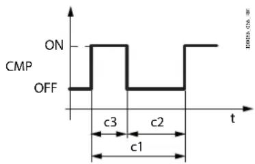
Fig. 8.x
| Ref. | Description |
| t | Time |
| CMP | Compressor |
8.9.1 Switching on and off
The compressor starts whenever the request is equal to the minimum speed in the allowed range. It stops when the request is equal to 0%.
Notice: the minimum and maximum compressor speed are pre-set values, defined by the manufacturer. Nonetheless, the minimum speed threshold (parameter Fci) can be increased or the maximum speed threshold (parameter CSM) can be reduced; the minimum off time and the minimum time between two consecutive starts are defined by parameters c2 and c1 respectively.
The sequence of the steps for compressor start-up control is shown below (see Fig. 8.y).

line
| time | Regulation request | BLDC Compressor | |------|---------------------|-----------------| | 1 | 100 | 0 | | 2 | 100 | 0 | | 3 | 100 | 0 | | 4 | 100 | 50 | | 5 | 80 | 70 | | 6 | 50 | 30 |Fig. 8.y
- Shutdown before start-up. The minimum time that must elapse before the compressor restarts is equal to the higher of the minimum off time and the minimum time between two successive starts. Compressor restart then depends on the request exceeding the minimum deliverable capacity;
- Start-up ramp. The compressor increases speed linearly, until reaching the start-up speed, defined by parameter CSS;
- Start-up phase. The compressor remains at speed CSS until time c3 has elapsed. This is a safety procedure designed to allow the oil to be distributed inside the compressor crankcase;
- Control phase. The compressor speed is based on the showcase control request;
- Low suction temperature protection. This phase occurs when the saturated evaporation temperature, converted from the evaporation pressure, reaches the threshold defined by parameter P11. The controller limits the compressor speed so as to keep the evaporation temperature above the value set for P11;
- Control phase. The control request and the compressor speed converge so as to keep the showcase temperature at the set point.
In the same way, the compressor shutdown phase is summarised in Fig. 8.z.

line
| time | Regulation request | BLDC Compressor | |------|---------------------|-----------------| | 0 | 100 | 100 | | 1 | ~70 | ~80 | | 2 | ~20 | ~50 | | 3 | 0 | ~50 | | 4 | 0 | 0 |Fig. 8.z
- Control phase. Compressor speed is modulated so as to meet the control request;
- Minimum control request. When the minimum control request is reached, the compressor speed is kept constant at the value defined by parameter Fci. The compressor remains at the minimum speed until the request reaches 0%;
- Shutdown ramp. As soon as the request reaches 0%, the compressor begins to linearly decrease speed until stopping;
- Compressor OFF phase. When there is no control request, the compressor remains off.
The behaviour of the electronic valve during the start-up, control and shutdown phases is shown in Fig. 8.aa.

line
| Time | Suction superheat (%) | EEV opening degree (%) | |------|------------------------|-------------------------| | 1 | ~20 | 50 | | 2 | ~60 | 100 | | 3 | ~30 | ~70 | | 4 | ~20 | 0 |Fig. 8.aa
- Equalisation and crankcase heating phase. The EEV remains open at the percentage defined by parameter SEP for the time Et, in order to equalise the pressure. At the same time, the compressor crankcase heating function is activated. This first phase ends when the higher of the two times, equalisation time (Et) and crankcase heating time (CSD), has elapsed;
- Pre-positioning phase. The electronic expansion valve remains at the pre-positioning percentage defined by parameter cP1, and remains there until the time cP2 has elapsed;
- Control phase. The EEV modulates its opening so as to maintain the superheat value around the set point, defined by parameter P3;
- Compressor shutdown. The electronic valve is closed completely.
8.8.3 Pump down
The pump down procedure can be enabled by setting parameter PDt.
| Code | Description | Def. | Min | Max | UOM | User | User term. |
| PDt | Type of pump down (0=none, 1=stop) | 0 | 0 | 1 | - | M | No |
During pump down:
• the compressor is operated at minimum speed;
• the ExV valve is closed;
• the evaporator fan is operated at the maximum allowed speed.
The compressor is stopped when the evaporation temperature reaches the limit defined by parameter LPd or when the maximum time CPt has elapsed.
| Code | Description | Def. | Min | Max | UOM | User | User term. |
| CPt | Maximum pump down time | 30 | 0 | 60 | s | M, S | No |
| LPd | Evaporation pressure limit for pump down | 11 | 0 | 45 | barg (psig) | M, S | No |
Tab. 8.ch
Tab. 8.ci
8.9 Generic functions
Heosone can exploit unused inputs and outputs to configure a "generic function".
Each generic function can be enabled/disabled from the APPLICA app or SPARK program.
The following can be activated (maximum configuration):
- 1 generic function with On/Off output;
• 1 generic function with modulating output;
• 1 generic alarm function (signal only).
The generic function can be controlled based on:
- 1 specific probe, or
- difference between 2 suitably configured probes.
Caution: the controller cannot verify the consistency of the settings, if two analogue functions are mistakenly assigned to the same analogue inputs or the same digital output.
8.9.1 Enabling
The generic function can be enabled always, or when the unit is in a certain status.
| Code | Description | Def. | Min | Max | UOM | User | User term. |
| GFS_E | On/Off generic function: enable0 = Always1 = Unit ON2 = Unit OFF3 = Defrost4 = Clean5 = Continuous cycle6 = Duty setting7 = Standby8 = Control9 = Open door10 = Active alarm | 0 0 10 | M, S | No | |||
| GFM_E | Modulating generic function: enable - see GFS_E | 0 | 0 | 10 | M, S | No | |
| GFA_E | Generic alarm function: enable - see GFS_E | 0 | 10 | M, S | No |
Tab. 8.a
Assign control probe
Select the control probes for the generic function.
| Code | Description | Def. | Min | Max | UOM | User | User term. |
| GFS_1 | On/Off generic function: control probe 10 : Not configured1 : Outlet temperature (Sm)2 : Defrost temperature (Sd)3 : Intake temperature (Sr)4 : Superheated gas temperature (tGS)5 : Saturated evaporation pressure (PEu)6 : Defrost temperature 2 (Sd2)7 : Auxiliary 1 (Saux1)8 : Auxiliary 2 (Saux2)9 : Room temperature (SA)10 : Room humidity (SU)11 : Glass temperature (Swt)12 : Dew point (SdP)13 : Virtual probe (5v)14 : Saturated evaporation temperature (tEu) | 0 0 14 - | M, S | No | |||
| GFS_2 | On/Off generic function: control probe 2 - see GFS_1 | 0 | 0 | 14 | - | M, S | No |
| GFM_1 | Modulating generic function: control probe 1 - see GFS_1 | 0 | 14 | - | M, S | No | |
| GFM_2 | Modulating generic function: control probe 2 - see GFS_1 | 0 | 0 | 14 | - | M, S | No |
| GFA_1 | Generic alarm function: control probe 1 - see GFS_1 | 0 | 0 | 14 | - | M, S | No |
| GFA_2 | Generic alarm function: control probe 2 - see GFS_1 | 0 | 0 | 14 | - | M, S | No |
Tab. 8.b
8.9.2 On/Off output
Assign the digital output for the generic function, the type (direct/reverse) and the activation logic (see parameter rOb).
| Code | Description | Def. | Min | Max | UOM | User | User term. |
| GFS_T | On/Off generic function: type 0=Direct, 1=Reverse | 0 | 0 | 1 | - | M, S | No |
| GFS_S | On/Off generic function: set point | -50 | 50 | - | M, S | No | |
| GFS_D | On/Off generic function: differential | 0 | 0 | 99.9 | - | M, S | No |
| DOS | On/Off generic function: digital output0 = disabled1 = NO12 = NO23 = NO3 | 0 | 0 | 3 | - | M | No |
| rOS | Digital output logic for generic alarm function - see rOb | 0 | 0 | 1 | - | M | No |
Tab. 8.c
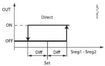
Fig. 8.ab

Ref. Description
| Set Set point |
| Diff Differential |
| Sreg1 Control probe 1 |
| Sreg2 Control probe 2 |
| OUT Digital output |
8.9.3 Modulating output
Assign the modulating output for the generic function and the type (direct/reverse). It is possible to use proportional control only or PID, as well as a cut-off differential with hysteresis.
| Code | Description | Def. | Min | Max | UOM | User | User term. |
| GFM_1 Modulating generic function: type0=Direct, 1=Reverse | 0 | 0 | 1 | - | M, S | No | |
| GFM_S | Modulating generic function: set point | 0 | -50 | 50 | - | M, S | No |
| GFM_D | Generic modulating function: differential | 0 | 0 | 99.9 | - | M, S | No |
| GFM_Kp | Modulating generic function: proportional gain | 0 | 0 | 100 | - | M, S | No |
| GFM_Td | Generic modulating function: derivative time | 0 | 0 | 100 | - | M, S | No |
| GFM_Ti | Modulating generic function: integral time | 0 | 0 | 900 | - | M, S | No |
| GFM_CD | Modulating generic function: cutoff differential | 0 | 0 | 20 | - | M, S | No |
| GFM_H | Modulating generic function: hysteresis | 0 | 0 | 20 | - | M, S | No |
| GFM_Max | Modulating generic function: max output value | 0 | 0 | 100 | - | M, S | No |
| GFM_Min | Modulating generic function: min output value | 0 | 0 | 100 | - | M, S | No |
| /Ad | Modulating generic function: analogue output0 = disabled1 = Y12 = Y2 | 0 | 0 | 2 | - | M, S | No |
Tab. 8.d
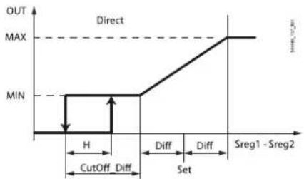
line
| Time Interval | Value | | ------------- | ----- | | Sreg1 - Sreg2 | MAX |Fig. 8.ac
| Ref. | Description |
| Set | Set point |
| Diff | Differential |
| H | Hysteresis |
| Sreq1 - Sreq2 | Control probe1 - Control probe 2 |
| OUT | Digital output |
| CutOff_Diff Cut-off differential | |
Alarm signal
The alarm can be signalled for two reasons:
- switching of the digital input, assigned by parameter DIs: the display shows "GHI"
- if the difference between the values of the control probes exceeds the high or low threshold: the display shows GHI or GLO respectively.
Notice: check each time that the alarm is generated by only one of the two causes.
| Code | Description | Def. | Min | Max | UOM | User | User term. |
| Dls | Assign digital input for generic alarm function - see DIA | 0 | 0 | 5 | - | M, S | No |
| GFA_De | General alarm function: delay | 0 | 0 | 254 | - | M, S | No |
| GFA_D | Generic alarm function: differential | 0 | 0 | 99.9 | - | M, S | No |
| GFA_Hth | Generic alarm function: high temperature threshold | 0 | -50 | 50 | - | M, S | No |
| GFA_Lth | General alarm function: low temperature threshold | 0 | -50 | 50 | - | M, S | No |
Tab. 8.e

line
| Time Segment | Signal | | ------------ | ------------- | | Del | On | | Del | Off | | Del | On | | Del | Off | | LTh+diff | On | | LTh+diff | Off | | HTh+diff | On | | HTh+diff | Off | | GHI | On | | GHI | Off | | GLO | On | | GLO | Off |Fig. 8.ad
Ref. Description
| Ith Low temperature threshold | |
| HTh High temperature threshold | |
| diff Differential | |
| Del Delay | |
| t Time | |
| Sreq1 - Sreq2 Control probe1 - Control probe 2 | |
| GHI High temperature alarm message | |
| GLO Low temperature alarm message | |
Example
Display of the generic alarm when exceeding the thresholds.

Fig. 8.ae
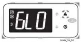
9. PARAMETER TABLE
Below is the table of the parameters that can be displayed on the terminal or can be modified using the commissioning software or APPLICA app. The APPLICA app and commissioning tools three predefined parameter access levels: User (U), Service (S) and Manufacturer (M). The default passwords to access the Service and Manufacturer parameters from the APPLICA Heosone app are 22 and 44 respectively. The Manufacturer level password also allows access to the Service parameters, and the level S password also allows access to the User parameters.
| Part number | Description | Def | Min | Max | UOM | User |
| PDM Manufacturer | password 44 0 99 - M | |||||
| PDS Service password | 22 0 99 - M | |||||
| PDU | User password | -0 99 - S | ||||
Tab. 9.a
Notice:
- the read-only parameters are not visible from the Applica app using NFC, as NFC memory cannot be overwritten frequently;
- to avoid any fraudulent activities, the default password values should be changed at the end of the commissioning procedure. For example, with the APPLICA app, parameters PDM, PDS and PDU can be used to set new passwords, with a maximum length of 8 characters, both alphanumeric and special.
Caution: the operation to reset the default values is not reversible, unless the unit configuration has been previously saved using the commissioning software/Applica app.
9.1 Parameter table
| Code | Description | Def | Min | Max | UOM | User | User term. |
| Analogue inputs | |||||||
| /2 | Analogue probe measurement stability | 9 | 1 | 15 | - | M, S | No |
| /P1 | Type of probe, group 1 (S1, S2, S3)0 = PT1000 Standard Range1 = NTC Standard Range2 = Reserved3 = Reserved4 = Reserved5 = NTC-HT | 1 | 0 | 5 | - | M, S | Yes |
| /P2 | Type of probe, group 2 (S4, SS)1 = NTC Standard Range2 = 0-5V3 = 4-20 mA4 = Reserved5 = NTC-HT6 = 0.5-4.5V | 6 | 1 | 6 | - | M, S | Yes |
| /P3 | Type of probe, group 3 (S6)0 = PT1000 Standard Range1 = NTC Standard Range2 = 0-5V3 = 4-20 mA4 = 0-10V5 = NTC-HT6 = 0.5-4.5V | 1 | 0 | 6 | - | M, S | Yes |
| /FA | Assign outlet temperature probe (Sm)0 = Function disabled1 = Probe S1 6 = Probe S6 | 1 | -4 | 6 | - | M, S | No |
| 2 = Probe S2 -1 = Serial probe S11 | |||||||
| 3 = Probe S3 -2 = Serial probe S12 | |||||||
| 4 = Probe S4 -3 = Serial probe S13 | |||||||
| 5 = Probe S5 -4 = Serial probe S14 | |||||||
| /Fb | Assign defrost temperature probe (Sd) - see /FA | 2 | -4 | 6 | - | M, S | No |
| /Fc | Assign intake temperature probe (Sr) - see /FA | 0 | -4 | 6 | - | M, S | No |
| /Fd | Assign superheated gas temperature probe (tGS) - see /FA | 3 | -4 | 6 | - | M, S | Yes |
| /Fe | Assign saturated evaporation pressure/temperature probe (PEu/tEu) - see /FA | 4 | -4 | 6 | - | M, S | Yes |
| /FF | Assign defrost temperature probe 2 (Sd2) - see /FA | 0 | -4 | 6 | - | M, S | No |
| /FG | Assign auxiliary temperature probe 1 (Saux1) - see /FA | 0 | -4 | 6 | - | M, S | No |
| /FH | Assign auxiliary temperature probe 2 (Saux2) - see /FA | 0 | -4 | 6 | - | M, S | No |
| /Fl | Assign ambient temperature probe (SA) - see /FA | 0 | -4 | 6 | - | M, S | No |
| /FL | Assign ambient humidity probe (SU) - see /FA | 0 | -4 | 6 | - | M, S | No |
| /FM | Assign glass temperature probe (Svt) - see /FA | 0 | -4 | 6 | - | M, S | No |
| /Fn | Assign dewpoint value (SdP) - see /FA | 0 | -4 | 6 | - | M, S | No |
| /Fo | Assign discharge temperature probe (Sdc) - see /FA | 0 | -4 | 6 | - | M, S | No |
| /Fs | Assign condensing pressure probe (Scp) - see /FA | 0 | -4 | 6 | - | M, S | No |
| /Fy | Assign condensing temperature probe - see /FA | 0 | -4 | 6 | - | M, S | No |
| /ca | Outlet temperature probe (Sm) calibration | 0 | -20 | 20 | °C (°F) | M, S | No |
| /cb | Defrost temperature probe (Sd) calibration | 0 | -20 | 20 | °C (°F) | M, S | No |
| /cc | Intake temperature probe (Sr) calibration | 0 | -20 | 20 | °C (°F) | M, S | No |
| /cd | Superheated gas temperature probe (tGs) calibration | 0 | -20 | 20 | °C (°F) | M, S | No |
| /cF | Saturated evaporation pressure probe (PFu) calibration | 0 | -20 | 20 | barg (psig) | M, S | No |
| /cF/cG | Defrost temperature probe 2 (Sd2) calibrationAuxiliary temperature probe 1 (Saux1) calibration 0 -20 20 °C (°F) M, S No | 0 | -20 | 20 | °C (°F) | M, S | No |
| /cH | Auxiliary temperature probe 2 (Saux2) calibration 0 -20 20 °C (°F) M, S No | ||||||
| /cl | Ambient temp. probe (SA) calibration 0 -20 20 °C (°F) M, S No | ||||||
| /cL | Ambient humidity probe (SU) calibration | 0 -20 20 %RH | M, S No | ||||
| /cM | Glass temperature probe (Svt) calibration | 0 | -20 | 20 | °C (°F) | M, S | No |
| /cn | Dowpoint value (SdP) calibration | 0 -20 20 °C (°F) M, S No | |||||
| /co | Discharge temperature probe (Sdc) calibration | 0 -20 20 °C (°F) M, S No | |||||
| /cs | Condensing pressure probe (Scp) calibration | 0 -20 20 barg (psig) M, S No | |||||
| /cy | Condensing temperature probe (Sc) calibration | 0 -20 20 °C/ (°F) M, S No | |||||
| /LE | Min. value for saturated evaporation pressure/temperature probe (PEu/tEu) | -1 | -1 | /UE | barg (psig) | M, S | Yes |
| /LL | Minimum value for ambient humidity probe (SU) | 10 | 10 | /UL | %RH | M, S | No |
| /LS | Minimum value for condensing pressure probe (Scp) | 0 | 0 | /US | barg (psig) | M, S | No |
| /UE | Max. value for saturated evaporation pressure/temperature probe (PEu/tEu) | 9.3 | /LE | 200 | barg (psig) | M, S | Yes |
| /UL | Maximum value for ambient humidity probe (SU) | 100 | /LL | 100 | %RH | M, S | No |
| /US | Maximum value for condensing pressure probe (Scp) | 44.8 | /LS | 200 | barg (psig) | M, S | No |
| Code | Description | Def | Min | Max | UOM | User | User term. |
| Digital inputs | |||||||
| DIA | Assign digital input for immediate external alarm0 = Function disabled1 = digital input 1 (ID1)2 = digital input 2 (ID2)3 = digital input 3 (ID3)4 = digital input 4 (ID4)5 = digital input 5 (ID5) | 0 | 0 | 5 | - | M, S | No |
| Dlb | Assign delayed external alarm digital input - see DIA | 0 | 0 | 5 | - | M, S | No |
| Dlc Assign enable defrost digital input - see DIA | 0 0 5 - | M, S No | |||||
| Dld Assign start defrost digital input - see DIA | 0 0 5 - | M, S No | |||||
| DIE | Assign digital input for door switch with compressor and evaporator fans OFF - see DIA | 0 | 0 | 5 | - | M, S | No |
| DIF | Assign remote ON/OFF digital input - see DIA | 0 | 0 | 5 | - | M, S | No |
| DIG | Assign curtain switch digital input - see DIA | 0 | 0 | 5 | - | M, S | No |
| DIH | Assign start/stop continuous cycle digital input - see DIA | 0 | 0 | 5 | - | M, S | No |
| DII | Assign input status monitoring digital input - see DIA | 0 | 0 | 5 | - | M, S | No |
| DIL | Assign timed digital input - see DIA | 0 | 0 | 5 | - | M, S | No |
| DIM | Assign digital input for switching to Standby mode - see DIA | 0 | 0 | 5 | - | M, S | No |
| Dln | Assign digital input for switching to Clean mode - see DIA | 0 | 0 | 5 | - | M, S | No |
| Dlp | Assign door switch without control stop digital input - see DIA | 0 | 0 | 5 | - | M, S | No |
| Dlr | Assign defrost according to DI status digital input - see DIA | 0 | 0 | 5 | - | M, S | No |
| Dls | Assign digital input for generic alarm function - see DIA | 0 | 0 | 5 | - | M, S | No |
| rIA | Immediate external alarm digital input logic0 = direct logic; 1 = reverse logic | 0 | 0 | 1 | - | M | No |
| rib | Delayed external alarm digital input logic - see rIA | 0 | 0 | 1 | - | M | No |
| rlc | Enable defrost digital input logic - see rIA | 0 | 0 | 1 | - | M | No |
| rld | Start defrost digital input logic - see rIA | 0 | 0 | 1 | - | M | No |
| rIE | Door switch with compressor OFF and evaporator fans OFF digital input logic - see DIA | 0 | 0 | 1 | - | M | No |
| rIF | Remote ON/OFF digital input logic - see rIA | 0 | 0 | 1 | - | M | No |
| rIG | Curtain switch digital input logic - see rIA | 0 | 0 | 1 | - | M | No |
| Rlh | Start/stop continuous cycle digital input logic - see rIA | 0 | 0 | 1 | - | M | No |
| rll | Input status monitoring digital input logic - see rIA | 0 | 0 | 1 | - | M | No |
| rIL | Timed digital input logic - see rIA | 0 | 0 | 1 | - | M | No |
| rIM | Standby mode switch digital input logic - see rIA | 0 | 0 | 1 | - | M | No |
| rln | Clean mode switch digital input logic - see rIA | 0 | 0 | 1 | - | M | No |
| rIP | Door switch without control stop digital input - see rIA | 0 | 0 | 1 | - | M | No |
| rir | Defrost according to DI status digital input logic - see rIA | 0 | 0 | 1 | - | M | No |
| rls | Generic alarm function digital input logic - see rIA | 0 | 0 | 1 | - | M | No |
| dlt | Timer duration (timed input); 0 = function disabled | 0 | 0 | 999 | min | M, S | No |
| Code | Description | Def | Min | Max | UOM | User | User term. |
| Digital outputs | |||||||
| DOb | Assign alarm digital output0 = not configured1 = digital output 1 (NO1)2 = digital output 2 (NO2)3 = digital output 3 (NO3) | 0 | 0 | 3 | - | M | No |
| DOA | Assign hot gas defrost digital output - see DOb | 0 | 0 | 3 | - | M | No |
| DOc | Assign digital output for auxiliary output - see DOb | 0 | 0 | 3 | - | M | No |
| DOE | Assign light digital output - see DOb | 0 | 0 | 3 | - | M | No |
| DOG | Assign defrost digital output - see DOb | 0 | 0 | 3 | - | M | No |
| DOI | Assign evaporator fan digital output - see DOb | 0 | 0 | 3 | - | M | No |
| DOo | Assign timed digital output - see DOb | 0 | 0 | 3 | - | M | No |
| DOP | Assign condensate drain heater digital output - see DOb | 0 | 0 | 3 | - | M | No |
| DOQ | Assign anti-sweat heater digital output - see DOb | 0 | 0 | 3 | - | M | No |
| DOS | Assign ON/OFF generic function digital output - see DOb | 0 | 0 | 3 | - | M | No |
| DOT | Assign condenser fan digital output - see DOb | 0 | 0 | 3 | - | M | No |
| rOb | Alarm digital output logic: 0=direct, 1=reverse | 0 | 0 | 1 | - | M | No |
| rOc | Auxiliary digital output logic - see rOb | 0 | 0 | 1 | - | M | No |
| rOE | Light digital output logic - see rOb | 0 | 0 | 1 | - | M | No |
| rOG | Defrost digital output logic - see rOb | 0 | 0 | 1 | - | M | No |
| rOIrOo Tim | Evaporator fan digital output logic - see rObed digital output logic - see rOb 0 0 1 - M No | 0 | 0 | 1 | - | M | No |
| rOP Condensate drain heater digital output logic - see rOb 0 0 1 - M No | |||||||
| rOQ Am | i-sweat heater digital output logic - see rOb 0 0 1 - M No | ||||||
| rOS | Digital output logic for generic ON/OFF function - see rOb | 0 | 0 | 1 | - | M | No |
| rOL | Condenser fan digital output logic - see rOb | 0 0 1 - M | No | ||||
| Code | Description | Def | Min | Max | UOM | User | User term. |
| Analogue outputs | |||||||
| /AA Assign analogue output for modulating evaporator fans0 = not configured1 = analogue output 1 (Y1)2 = analogue output 2 (Y2) | 0 0 2 - M,S | No | |||||
| /Ac Assign analogue output for modulating anti-sweat heaters - see /AA | 0 | 0 | 2 | - | M,S | No | |
| /Ad Assign analogue output for generic function - see /AA 0 0 2 - M,S No | |||||||
| /Ac Assign channel for modulating condensing fan output - see /AA | 0 | 0 | 2 | - | M,S | No | |
| Code | Description | Def | Min | Max | UOM | User | User term. |
| Control | |||||||
| cdt | PID control: derivative time | 0 | 0 | 100 | s | M,S | No |
| cPr | PID control: proportional gain | 2 | 0 | 100 | %/°C | M,S | No |
| ctl | PID control: integral time | 100 | 0 | 900 | s | M,S | No |
| ON | ON/OFF command0=OFF, 1=ON | 101-M5 No | |||||
| /4 | Virtual probe composition0 = Outlet probe Sm100 = Intake probe Sr | 00100 | % | M,S,J | No | ||
| r1 | Minimum set point | -50 | -50 | r2 | °C(°F) | M | No |
| r2 | Maximum set point | 50 | r1 | 50 | °C(°F) | M | No |
| r4 | Automatic night set point variation | 0 | -50 | 50 | °C(°F) | M | No |
| r6 | Probe for night-time control0=virtual probe Sv, 1=intake probe Sr | 0 | 0 | 1 | - | M | No |
| ro | Control offset with probe error | 0 | 0 | 20 | °C(°F) | M | No |
| St | Set point | 50 | r1 | r2 | °C(°F) | M,S,U | No |
| rHS Virtual probe composition for glass temp. probe estimate0 = Outlet probe Sm100 = Intake probe Sr | 20 | 0100 | % | M No | |||
| rHA | Coeff. A for glass temp. probe estimate | 2 | -20 | 20 | °C(°F) | M | No |
| rHb | Coeff. B for glass temp. probe estimate | 22 | 0 | 100 | - | M | No |
| rHo | Offset for anti-sweat modulation | 2 | -20 | 20 | °C(°F) | M | No |
| rHd | Differential for anti-sweat heater modulation | 0 | 0 | 20 | °C(°F) | M | No |
| rHu | Manual anti-sweat heater activation percentage (of period "rHt")0 = function disabled | 70 | 0100 | % | M No | ||
| rHt Manual anti-sweat heater activation period0 = function disabled | 50180 | min | M No | ||||
| CLt | Max time for Clean status | 0 | 0 | 999 | min | M | No |
| Stt | Maximum time for Standby status | 0 | 0 | 240 | min | M | No |
| H14 | Time light stays on after closing the door | 0 | 0 | 240 | min | M,S | No |
| Code | Description | Def | Min | Max | UOM | User | User term. |
| Defrost | |||||||
| d0 | Type of defrost0 = heater by temperature1 = hot gas by temperature2 = heater by time3 = hot gas by time4 = heater by time with temperature control | 0 | 0 | 4 | M, S | No | |
| dl | Maximum interval between consecutive defrosts | 8 | 0 | 240 | h | M, S, U | Yes |
| dt1 | End defrost temperature (read by 5d) | 8 | -50 | 50 | °C (°F) | M, S, U | Yes |
| dt2 | End defrost temperature (read by 5d2) | 8 | -50 | 50 | °C (°F) | M, S | No |
| dP1 | Maximum defrost duration | 45 | 1 | 240 | min | M, S, U | Yes |
| dP2 | Max secondary evap. defrost duration | 45 | 1 | 240 | min | M, S | No |
| d4 | Defrost at power onFALSE = disabledTRUE = enabled | 0 | 0 | 1 | M, S | No | |
| d5 | Defrost delay at power on0 = delay disabled | 0 0 240 | min | M, S | No | ||
| d6 | Display on terminals during defrost0 = temperature alternating with "DEF"1 = freeze display2 = "DEF" | 1 | 0 | 2 | M, S | No | |
| dd | Dripping time after defrost (fans off)0 = no dripping | 2 0 15 | min | M, S | No | ||
| d7 | Skip defrost: 0 = disabled; 1 = enabled | 0 | 0 | 1 | M, S | No | |
| d8 | Bypass high temperature alarm time after defrost | 30 | 1 | 240 | min | M, S | No |
| d9 | Defrost priority over compressor protection times0 = protection times observed; 1 = protection times not observed | 1 | 0 | 1 | M, S | No | |
| d10 | Defrost time in running time mode0 = function disabled | 0 0 240 | min | M, S | No | ||
| d11ds1 | Defrost temperature threshold in running time modeCompressor off time in sequential stop defrost mode0 = function disabled | -300 0 45 m | -50n M No | 50 | °C (°F) | M, S | No |
| ds2 | Compressor operating time in sequential stop defrost mode 120 0 240 min M No | ||||||
| ddt | Additional end defrost temperature delta in power defrost mode 0 - 20 20 °C (°F) M, S | No | |||||
| ddP | Additional maximum defrost time delta in power defrost mode | 0 | 0 | 60 | min | M, S | No |
| dn | Nominal skip defrost duration | 75 | 0 | 100 | % | M, S | No |
| r3 | End defrost signal by timeout0 = disabled; 1 = enabled | 0 | 0 | 1 | - | M | No |
| c7 | Defrost priority over continuous cycle0 = No; 1 = Yes | 0 | 0 | 1 | - | M | No |
| dVt | Electronic valve pre-opening time to equalise the pressure after defrosting | 60 | 0 | 999 | s | M | No |
| dVP | Electronic valve: pre-opening for pressure equalisation after defrost | 100 | 0 | 100 | % | M | No |
| dPt | Drain heater activation delay after start defrost | 60 | 0 | 999 | s | M | No |
| drd | Control valve activation delay after starting the compressor when defrost ends | 180 | 0 | 999 | s | M | No |
| dSa | Valve position at start defrost (0 = automatic, 1 = closed, 2 - 100 = opening percentage) | 0 0 100 % | M | No | |||
| Code | Description | Def | Min | Max | UOM | User | User term. |
| Defrost scheduling | |||||||
| td1..8-d | Defrost 1 to 8 - day0 = event disabled1 to 7 = Monday to Sunday8 = Monday to Friday9 = from Monday to Saturday10 = Saturday & Sunday11 = every day | 0 0 11 d | M,S,U No | ||||
| td1..8-time | Defrost 1 to 8 - start time (hh:mm) | 00:00 | 00:00 | 23:59 | - | M,S,U | No |
| td1..8-P Defrost | 1 to 8 - enable power defrost:0 = normal; 1 = power defrost | 0 0 1 - | M,S,U No | ||||
| d1S | Number of daily defrosts (td1)0 = Disabled1 = 24 hours and 0 minutes2 = 12 hours and 0 minutes3 = 8 hours and 0 minutes4 = 6 hours and 0 minutes5 = 4 hours and 48 minutes6 = 4 hours and 0 minutes7 = 3 hours and 26 minutes8 = 3 hours and 0 minutes9 = 2 hours and 40 minutes10 = 2 hours and 24 minutes11 = 2 hours and 11 minutes12 = 2 hours and 0 minutes13 = 1 hour and 0 minutes14 = 30 minutes | 0 0 14 - | M,S No | ||||
| d2S | Number of daily defrosts (td2) - see d1S | 0 | 0 | 14 | - | M,S | No |
| Code | Description | Def | Min | Max | UOM | User | User term. |
| Evaporator fans | |||||||
| F0 | Evaporator fan management0 = always on1 = activation based on Sa - Sb (see FSa and FSb)2 = activation based on Sa(Sa = first probe, Sb = second probe) | 0 0 2 - | M, S, U No | ||||
| F1 | Evaporator fan activation threshold (only if F0 = 1 or 2) | -5 | -50 | 50 | °C (°F) | M, S, U | No |
| F2 | Evaporator fans with compressor off0 = see F01 = always off | 1 0 1 - | M, S, U No | ||||
| F3 | Evaporator fans during defrost0 = on; 1 = off | 1 | 0 | 1 | - | M, S | No |
| Fd | Post-dripping time after defrost (fans off with control active) | 2 0 15 m | n M No | ||||
| Frd | Fan activation differential (including variable speed) | 2 | 0.1 | 20 | °C (°F) | M, S | No |
| F5 | Evap. fan cut-off temperature (hyst. 1°C) | 50 | F1 | 50 | °C (°F) | M, S | No |
| F6 | Max evaporator fan speed | 23 | F7 | 100 | % | M, S | No |
| F7 | Min evaporator fan speed | 15 | 0 | F6 | % | M, S | No |
| F8 | Evaporator fan peak time0 = Function disabled | 0 0 240 s | M, S No | ||||
| F10 | Evaporator fan forcing time at max speed0 = Function disabled | 0 0 240 min M, S | No | ||||
| FSa First fan | control probe0 : Not configured1 : Outlet (Sm)2 : Defrost (Sd)3 : Intake (Sr)4 : Superheated gas (tGS)5 : Saturated evaporation pressure (PEu)6 : Defrost 2 (Sd2)7 : Auxiliary 1 (Saux1)8 : Auxiliary 2 (Saux2)9 : Ambient (SA)10 : Room humidity (SU)11 : Glass temperature (Svt)12 : Dew point (SdP)13: Virtual probe (Sv)14 : Saturated evaporation temperature (tEu) | 2014 - M, S No | |||||
| FSb Second | fan control probe - see FSa 13014 - M, S No | ||||||
| Fpd Evaporator fans during post-dripping0 = On; 1 = Off | 1 | 0 | 1 | - | M No | ||
| POM | Unit cooling capacity indication | 0 | 0 | 32000 | watts | No | |
| EF1_Speed | Evaporator fan speed associated with output PWM 1 | - | - | - | rpm | M, S, U | No |
| EF2_Speed | Evaporator fan speed associated with output PWM 2 | - | - | - | rpm | M, S, U | No |
| ME | Request in evaporator fan manual mode | 0 | 0 | 100 | % | M,S | No |
| MEE | Evaporator fan: enable manual mode (0=No, 1=Yes) | 0 | 1 | 0 | - | M,S | No |
| PWM1_Max | Maximum condensing fan speed (with PWM signal) | 1800 | 0 | 1800 | rpm | M,S | No |
| PWM1_Type | Type of fan associated with output PWM1 (J4):0: none1: evaporator fan2: condenser fan | 002 - M,S | No | ||||
| Code | Description | Def | Min | Max | UOM | User | User term. |
| EEV (Electronic expansion valve) | |||||||
| P1 | Electronic valve0 = not present1 = OnBoard driver | 1 | 0 | 1 | - | M Yes | |
| P3 | Superheat set point | 10 | 0 | 25 | K | M, S, U | Yes |
| P4 | Proportional gain | 15 | 0 | 100 | - | M | No |
| P5 | Integral time0 = function disabled | 150 | 0 | 900 | s | M | No |
| P6 | Derivative time0 = function disabled | 5 0 100 | s | M | No | ||
| P7 | LowSH: low superheat threshold | 2 | -10 | P3 | K | M, S | No |
| P8 | LowSH: integral time0 = function disabled | 10 0 240 | s | M | No | ||
| P9 | LowSH: alarm delay0 = alarm disabled | 120 | 0 | 999 | s | M | No |
| P10 | Enable unit shutdown due to low superheat (LSH) and/or low suction temperature (LSA) alarm - 1=enable closing | 0 | 0 | 1 | - | M, S | No |
| P11 | LSA: low suction temperature threshold | -35 | -50 | 50 | °C | M, S | No |
| P12 | LSA: alarm delay0 = alarm disabled | 120 | 0 | 999 | s | M | No |
| P14 | Enable valve alarm at end travel ("blo")1 = signal enabled | 1 | 0 | 1 | - | M No | |
| PM1 | MOP: max saturated evap. temp. threshold | 50 | -50 | 50 | °C | M, S | No |
| PM2 | MOP: integral time | 20 | 0 | 800 | s | M | No |
| PM3 | MOP: alarm delay 0 = function disabled | 240 | 0 | 999 | s | M | No |
| PM4 | MOP: function activation delay when starting control | 2 | 0 | 240 | s | M | No |
| PM6 | MOP: max suction temp. threshold | 50 | -50 | 50 | °C (°F) | M, S | No |
| PL1 | LOP: min saturated evap. temp. threshold | 50 | -50 | 50 | °C | M, S | No |
| PL2 | LOP: integral time | 10 | 0 | 800 | s | M, S | No |
| PL3 | LOP: alarm delay - 0 = function disabled | 120 | 0 | 240 | s | M, S | No |
| cP1 | Initial valve position when control starts | 30 | 0 | 100 | % | M, S | No |
| Pdd | Initial valve position maintenance time after defrost | 0 | 0 | 30 | min | No | |
| dSb Valve position during defrost0: as defined by the type of defrost1: forced closed2 to 100: opening percentage | 0 0 100 | % | M, S | No | |||
| PMP | Enable manual expansion valve positioning0 = disabled; 1 = enabled | 0 | 0 | 1 | - | M, S | No |
| PMu | Manual valve position | 0 | 0 | 480 | steps | M, S | No |
| cP2 | Electronic valve control delay at start-up | 0 | 0 | 999 | s | M, S | No |
| SEP | Electronic valve: pre-opening for pressure equalisation | 10 | 0 | 100 | % | M | No |
| Et | Maximum electronic valve pre-opening time to equalise the pressure(0-equalisation disabled) | 0 3600 s | M, S No | ||||
| Compressor | |||||||
| c0 Delay to enable compressor and evaporator fans at power on 0 0 15 min M, S No | |||||||
| c1 Min | time between consecutive compressor starts 360 0 999 s M No | ||||||
| c2 Min | compressor OFF time 360 | 0 999 s M | No | ||||
| c3 Min | compressor ON time 360 | 0 999 s M | No | ||||
| c4 ON | time for duty setting operation (Toff = 15 minutes, fixed value)0 = compressor/valve always OFF100 = compressor/valve always ON | 0 0 100 min M | No | ||||
| cc Run | ting time in continuous cycle0 = Disabled | 0 | 0 | 15 | h | M | No |
| c6 | Low temp. alarm bypass time after continuous cycle | 60 | 0 | 240 | min | M | No |
| Ard | Compressor protection: reduction time | 15 0 999 s M, S No | |||||
| cds | Minimum pressure delta to consider the compressor running | 0.1 | 0 | 9.9 | barg (psig) | M | No |
| cEc | Enable crankcase heater function | 1 | 0 | 1 | - | M | No |
| cI3 | Compressor operating percentage with broken control probe | 50 | 0 | 100 | % | M, S | No |
| cMt | Minimum waiting time for the crankcase heater function whenthe compressor is stopped | 60 0 9999 min M, S | No | ||||
| cPd | Evaporator temperature delta to stop compressor | 6 | 0 | 99.9 | K | M, S | No |
| CPt | Maximum pump down time | 30 0 60 s M, S No | |||||
| CSD | Crankcase heater delay when starting the compressor | 60 | 0 | 999 | s | M | No |
| CSM | Maximum compressor activation speed (custom) | 90 | - | - | rps | M | No |
| CSS | Compressor start-up speed | 50 | - | - | rps | M | No |
| Fcd | Intermediate compressor activation speed (custom) | 45 | Fci | CSM | rps | M | No |
| Fci | Minimum compressor activation speed (custom) | 20 | - | - | rps | M | No |
| MC | Compressor: request in manual mode | 0 | 0 | 100 | % | M, S | No |
| MFC | Compressor - enable manual mode (0=No, 1=Yes) | 0 | 0 | 1 | - | M, S | No |
| PDt | Type of pump down (0=none, 1=stop) | 0 | 0 | 1 | - | M | No |
| LPd | Evaporation pressure limit for pump down | 11 | 0 | 45 | barg (psig) | M, S | No |
| Code | Description | Def | Min | Max | UOM | User | User term. |
| Condenser fans | |||||||
| /LS | Minimum value for condensing pressure probe (Scp) | 0 | -1 | /US | barg (psig) | M, S | No |
| /US | Maximum value for condensing pressure probe (Scp) | 44.8 | /LS | 200 | barg (psig) | M, S | No |
| CF0 | Proportional gain for condensing fan control | 5 | - | - | - | M, S | No |
| CF1 | Integral time for condensing fan control | 70 | - | - | s | M, S | No |
| CF1_Speed | Condenser fan speed associated with output PWM 1 | rpm | M, S, U | No | |||
| CF2_Speed | Condenser fan speed associated with output PWM 2 | rpm | M, S, U | No | |||
| Cfd | Condenser fan control mode(TRUE = control based on condensing temperature probe,FALSE = control based on compressor speed) | 1 | 0 | 1 | - | M | No |
| cHd | High discharge temperature differential | 1050 °C (°F) M, S No | |||||
| cHt | High discharge temperature threshold | 1050 150 °C (°F) M, S No | |||||
| CtS | Condensing temperature set point | 0 | - | - | °C (°F) | M, S | No |
| FAE | Condenser fan analogue output status | M, S | No | ||||
| FAT | Enable fan auto-tuning (0=No, 1=Yes) | No | No | Yes | - | M | No |
| FCH | Maximum condensing fan speed, expressed as a percentageof maximum speed PWM1_Max | 19 FCM | 100 % | M No | |||
| FCL | Minimum condensing fan speed, expressed as a percentage of maxi-mum speed PWM1_Max | 100 FCM | % | M | No | ||
| FCM | Minimum condensing fan speed, expressed as a percentage of maxi-mum speed PWM1_Max | 15 FCL FCH % | M | No | |||
| MEF | Condenser fan: enable manual mode (0=No, 1=Yes) | 0 | 0 | 1 | - | M, S | No |
| MF | Condenser fan: request in manual mode | 0 | 0 | 100 | % | M, S | No |
| PWM2_Max | Maximum condensing fan speed (with PWM signal) | 1800 | 0 | 1800 | rpm | M, S | No |
| PWM2_Type | Type of fan associated with output PWM2 (J3):0: none1: evaporator fan2: condenser fan | 0 | 0 | 2 | - | M, S | No |
| Code | Description | Def | Min | Max | UOM | User | User term. |
| Alarms | |||||||
| A0 | High and low temp. alarm reset differential | 2 | 0.1 | 20 | °C (°F) | M, S | No |
| A1 Alarm thresholds (AL, AH) relative to the set point St or absolute0 = relative; 1 = absolute | 0 0 1 - | M, S, U No | |||||
| A2 Alarm thresholds (AL2, AH2) relative to the set point St2 or absolute0 = relative; 1 = absolute | 0 | 0 | 1 | - | M, S | No | |
| A6 Configure compressor control during external alarm (immediate or delayed)with fixed 15 min OFF time0 = always OFF; 100 = always ON | 0 0 100 min | M, S No | |||||
| A11 Delay time for delayed external alarm0 = Signal-only alarm | 0 0 240 min | M, S No | |||||
| AA Assign probe for high (AH) and low (AL) temperature alarms0: Not configured1: Outlet (Sm)2: Defrost (Sd)3: Intake (Sr)4: Superheated gas (tGS)5: Reserved6: Defrost 2 (Sd2)7: Auxiliary 1 (Saux1)8: Auxiliary 2 (Saux2)9: Ambient (SA)10: Reserved11: Glass temperature (Svt)12: Dew point (SdP)13: Virtual probe (Sv)14: Saturated evaporation temperature (tEu) | 1014 - M, S No | ||||||
| AA2 Assign probe for high (AH2) and low (AL2) temperature alarms - see AA 1014 - M, S No | |||||||
| AL High temp. alarm threshold 4-50 50 °C (°F) M, S Yes | |||||||
| AH Low temp. alarm threshold 10-50 50 °C (°F) M, S, U Yes | |||||||
| AL2 | High temp. alarm 2 threshold | 0 | -50 | 50 | °C (°F) | M, S | No |
| AH2 Low temp. alarm 2 threshold 0-50 50 °C (°F) M, S No | |||||||
| Ad | Delay time for high and low temp. alarms (AH, AL) | 120 | 0 | 240 | min | M, S | Yes |
| Ad2 | Delay time for high and low temp. alarms (AH2, AL2) | 30 | 1 | 240 | min | M, S | No |
| Add | High temp. alarm bypass time for door open | 30 | 1 | 240 | min | M, S | No |
| Tdoor | Door open: alarm delay | 30 | 1 | 240 | min | M | No |
| Htd | HACCP alarm delay0 = monitoring disabled | 00240 | min M, S, U No | ||||
| Code | Description | Def | Min | Max | UOM | User | User term. |
| Connectivity | |||||||
| H0 | Serial address | 199 | 1 | 247 | - | M,S | No |
| H1 | BMS serial port configuration (stop bits and parity)0 = 1 stop bit, no parity1 = 2 stop bit, no parity2 = 1 stop bit, even parity3 = 2 stop bit, even parity4 = 1 stop bits, odd parity5 = 2 stop bits, odd parity | 1 | 0 | 5 | - | M,S | No |
| H2 | BMS serial port baud rate (bit/s)0 = 12001 = 24002 = 48003 = 96004 = 192005 = 384006 = 576007 = 115200 | 407 - M,S Yes | |||||
| H3 | BMS serial port protocol0= Carel; 1=Modbus | 101 - M,S Yes | |||||
| Code | Description | Def | Min | Max | UOM | User | User term. |
| Fieldbus | |||||||
| H4 | FBus serial port baud rate (bit/s)0 = 12001 = 24002 = 48003 = 96004 = 192005 = 384006 = 576007 = 1152008 = 375000 | 4 | 0 | 8 | - | M,S | No |
| Code | Description | Def | Min | Max | UOM | User | User term. |
| Display | |||||||
| /5 | Unit of measure: 0 = °C/barq; 1 = °F/psig | 0 | 0 | 1 | - | M, S | No |
| /6 | Display decimal point: 0 = Yes; 1 = No | 0 | 0 | 1 | - | M, S | No |
| /t1 | Display on user terminal0 = Terminal disabled1 to 6 = Probe 1 to 67, 8 = Reserved9 = Control probe10 = Virtual probe11 to 14 = Serial probe 1 to 415 = Temperature set point | 9015 - M, S | No | ||||
| H5 | Enable keypad and NFC functions: 0 = Disabled; 1 = Enabled | 1 | 0 | 1 | - | M, S | No |
| H6 | Enable 7-segment display | 1 | 0 | 1 | - | M, S | No |
| H8 Buzzer: 0 = Yes; 1 = No 1 0 1 - M No | |||||||
| Code | Description | Def | Min | Max | UOM | User | User term. |
| Day/Night | |||||||
| tS1..8-d | Start time band 1 to 8: day - see (td1..8-d) | 0 | 0 | 11 | d | M, S, U | No |
| tS1..8-time | Start time band 1 to 8: time | 00:00 | 00:00 | 23:59 | - | M, S, U | No |
| tE1..8-d | End time band 1 to 8: day - see (td1..8-d) | 0 | 0 | 11 | d | M, S, U | No |
| tE1..8-time | End time band 1 to 8: time | 00:00 | 00:00 | 23:59 | - | M, S, U | No |
| Code | Description | Def | Min | Max | UOM | User | User term. |
| Generic function | |||||||
| GFS_E | On/Off generic function: enable0 = Always1 = Unit ON2 = Unit OFF3 = Defrost4 = Clean5 = Continuous cycle6 = Duty setting7 = Standby8 = Control9 = Open door10 = Active alarm | 0 0 10 | - M, S | No | |||
| GFS_1 | On/Off generic function: control probe 10 : Not configured1 : Outlet temperature (Sm)2 : Defrost temperature (Sd)3 : Intake temperature (Sr)4 : Superheated gas temperature (tGS)5 : Saturated evaporation pressure (PEu)6 : Defrost temperature 2 (Sd2)7 : Auxiliary 1 (Saux1)8 : Auxiliary 2 (Saux2)9 : Room temperature (SA)10 : Room humidity (SU)11 : Glass temperature (Svt)12 : Dow point (SdP)13 : Virtual probe (Sv)14 : Saturated evaporation temperature (tEu) | 0 0 14 | - M, S | No | |||
| GFS_2 | On/Off generic function: control probe 2 - see GFS_1 | 0 | 0 | 14 | - | M, S | No |
| GFS_T | On/Off generic function: type - 0/1 = Direct/Reverse | 0 | 0 | 1 | - | M, S | No |
| GFS_S | On/Off generic function: set point | -50 | 50 | M, S | No | ||
| GFS_D | On/Off generic function: differential | 0 | 0 | 99.9 | M, S | No | |
| DOS | On/Off generic function: digital output0 = disabled1 = NO12 = NO23 = NO3 | 0 | 0 | 3 | - | M | No |
| rOS | On/Off generic function: logic - 0/1 = Direct/Reverse | 0 | 0 | 1 | - | M | No |
| GFM_E | Modulating generic function: enable - see GFS_E | 0 | 0 | 10 | - | M, S | No |
| GFM_I | Modulating generic function: control probe 1 - see GFS_I | 0 | 14 | - | M, S | No | |
| GFM_2 | Modulating generic function: control probe 2See GFS_1 | 0 0 14 | - M, S | No | |||
| GFM_T | Modulating generic function: type0/1 = Direct/Reverse | 0 | 0 | 1 | - | M, S | No |
| GFM_S | Modulating generic function: set point | 0 | -50 | 50 | - | M, S | No |
| GFM_D | Generic modulating function: differential | 0 | 0 | 99.9 | - | M, S | No |
| GFM_Kp | Modulating generic function: proportional gain | 0 | 0 | 100 | - | M, S | No |
| GFM_Td | Generic modulating function: derivative time | 0 | 0 | 100 | - | M, S | No |
| GFM_Ti | Modulating generic function: integral time | 0 | 0 | 900 | - | M, S | No |
| GFM_CD | Modulating generic function: cutoff differential | 0 | 0 | 20 | - | M, S | No |
| GFM_H | Modulating generic function: hysteresis | 0 | 0 | 20 | - | M, S | No |
| GFM_Max | Modulating generic function: max output value | 0 | 0 | 100 | - | M, S | No |
| GFM_Min | Modulating generic function: min output value | 0 | 0 | 100 | - | M, S | No |
| /Ad | Modulating generic function: analogue output0 = disabled1 = Y12 = Y2 | 0 | 0 | 2 | - | M, S | No |
| GFA_E | Generic alarm function: enable - see GFS_E | 0 | 10 | - | M, S | No | |
| GFA_1 | Generic alarm function: control probe 1 - see GFS_1 | 0 | 0 | 14 | - | M, S | No |
| GFA_2 | Generic alarm function: control probe 2 - see GFS_1 | 0 | 0 | 14 | - | M, S | No |
| GFA_De | General alarm function: delay | 0 | 254 | - | M, S | No | |
| GFA_D | Generic alarm function: differential | 0 | 99.9 | - | M, S | No | |
| GFA_Hth | Generic alarm function: high temperature threshold | -50 | 50 | - | M, S | No | |
| GFA_Lth | General alarm function: low temperature threshold | -50 | 50 | - | M, S | No | |
Tab. 9.b
10. ALARMS AND SIGNALS
10.1 Signals
Signals are messages shown on the display to notify the user of the control procedures in progress (e.g. defrost) or to confirm keypad input.
Code Description
| dEF Defrost running |
| Ed1 Defrost on evaporator 1 ended by timeout |
| Ed2 Defrost on evaporator 2 ended by timeout |
| OFF Switch OFF |
| Stb Standby status |
| CLn Clean status |
| dAd Last defrost not performed (defrost probe reading over threshold dt1 at start of defrost) |
| dEA Early end defrost warning |
| dFd Download inverter default parameter warning |
Tab. 10.a
10.2 Types of alarms
There are three types of alarms:
- system: EEPROM, communication, HACCP, high (HI and HI2) and low (LO and LO2) temperature;
• control: low superheat (LowSH), low evaporation pressure (LOP), high evaporation pressure (MOP), low suction temperature (LSA); - generic alarm function, signal only (see Functions for the corresponding parameters).
The EEPROM memory alarm always shuts down the controller. The digital outputs can be configured to signal the alarm status, normally open or normally closed. See "Digital outputs". The controller displays alarms due to faults on the controller itself or on the probes. An alarm can also be activated from an external contact, immediate or delayed. See "Digital inputs". The display shows "IA" and at the same time the alarm icon (triangle) flashes and the buzzer is activated. If more than one error occurs, these are displayed in sequence. A maximum of 10 errors can be saved, in a FIFO list. The error log can be accessed from the user terminal, via supervisor or Applica app (BLE connection only).
10.2.1 Active alarms
Active alarms are signalled by the buzzer and the flashing of the ALARM
button. Pressing ALARM will mute the buzzer and display the alarm code. Alarm activation is recorded in the alarm log.
If the alarm is reset automatically, the ALARM button goes off, the alarm code is cleared from the list and the alarm reset event is recorded in the alarm log.
Procedure (alarm acknowledgement):
- press ALARM: the buzzer is muted, the alarm code is shown on the display;
- press UP/DOWN to scroll through the list of alarms;
- when finished, press ESC and then PRG to exit.
Example
Display after HI error.
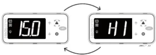
Fig. 10.a
A single alarm can be reset by pressing ALARM for more than 3 s. If the condition that generated the alarm is still present, the alarm will be reactivated. The alarm log can be deleted via APPLICA on a smartphone, with BLE connection, using the specific function on the alarm page ("Service" level access is required).
Notice: deletion of the alarm log is irreversible.
10.3 Display alarm log
The alarm log can be displayed via the supervisor, the APPLICA app with Bluetooth connection or on the user interface.
Procedure:
- press PRG until displaying: "PSD";
- enter the Password 33;
- press UP/DOWN until reaching the ALM category; confirm by pressing PRG;
- press UP/DOWN until displaying "HSt": a submenu is opened, where the UP and DOWN buttons can be used to scroll through the alarms, from HS0 to HS9;
- select an alarm by pressing PRG and display the code, date, time, minutes and duration (if reset)
- press ESC one or more times to retrun to the standard display.
Example:
$$ ^ {\prime \prime} H I ^ {\prime \prime} - > ^ {\prime \prime} y 1 8 ^ {\prime \prime} - > ^ {\prime \prime} m 1 1 ^ {\prime \prime} - > ^ {\prime \prime} d 2 0 ^ {\prime \prime} - > ^ {\prime \prime} h 1 7 ^ {\prime \prime} - > ^ {\prime \prime} m 2 3 ^ {\prime \prime} - > ^ {\prime \prime} 6 5 ^ {\prime \prime} $$
indicates that "HI" (high temperature alarm) occurred on 20/11/2018 at 17:23 and lasted 65 minutes.
10.4 Alarm table
| Code | Description | Reset | Effect | Buzzer | LED | Priority | Delay (s) | No. of activations | Evaluation period (s) |
| A20 | Overcurrent Semi-auto Compressor | off. Up to five | Restart attempts without considering the timers | √ | √ | Normal 0 | 5 | 3600 | |
| A21 | HW overcurrent | Semi-auto Compressor off. Up to five restart attempts without considering the timers | √ | √ | Normal 0 | 5 | 3600 | ||
| A22 | Overcurrent rms | Semi-auto Compressor off. Up to five restart attempts without considering the timers | √ | √ | Normal 0 | 5 | 3600 | ||
| A23 | Current measurement error | Semi-auto Compressor off. Up to five restart attempts without considering the timers | √ | √ | Normal 0 | 5 | 3600 | ||
| A24 | Unbalanced compressor currents | Semi-auto Compressor off. Up to five restart attempts without considering the timers | √ | √ | Normal 0 | 5 | 3600 | ||
| A25 | Overvoltage | Semi-auto Compressor off. Up to five restart attempts without considering the timers | √ | √ | Normal 0 | 5 | 3600 | ||
| A26 | Undervoltage | Semi-auto Compressor off. Up to five restart attempts without considering the timers | √ | √ | Normal 0 | 5 | 3600 | ||
| A27 | DC bus ripple | Semi-auto Compressor off. Up to five restart attempts without considering the timers | √ | √ | Normal 0 | 5 | 3600 | ||
| A28 | DC bus voltage out-of-range Semi-auto Compressor off. Up to five restart attempts without considering the timers | √ | √ | Normal 0 | 5 | 3600 | |||
| A29 | DC bus voltage measurement error | Semi-auto Compressor off. Up to five restart attempts without considering the timers | √ | √ | Normal 0 | 5 | 3600 | ||
| A30 | Power overload | Semi-auto Compressor off. Up to five restart attempts without considering the timers | √ | √ | Normal 0 | 5 | 3600 | ||
| A31 | Input voltage out of range | Semi-auto Compressor off. Up to five restart attempts without considering the timers | √ | √ | Normal 0 | 5 | 3600 | ||
| A32 | Power supply voltage acquisition error | Semi-auto Compressor off. Up to five restart attempts without considering the timers | √ | √ | Normal 0 | 5 | 3600 | ||
| A33 | Compressor stall | Semi-auto Compressor off. Up to five restart attempts without considering the timers | √ | √ | Normal 0 | 5 | 3600 | ||
| A34 | Low cosphi | Semi-auto Compressor off. Up to five restart attempts without considering the timers | √ | √ | Normal 0 | 5 | 3600 | ||
| A35 | STD line open | Semi-auto Compressor off. Up to five restart attempts without considering the timers | √ | √ | Serious | 0 | 5 | 3600 | |
| A36 | STD fault | Semi-auto Compressor off. Up to five restart attempts without considering the timers | √ | √ | Serious | 0 | 5 | 3600 | |
| A37 | CPU error | Semi-auto Compressor off. Up to five restart attempts without considering the timers | √ | √ | Normal 0 | 5 | 3600 | ||
| A38 | CRC error on parameters | Semi-auto Compressor off. Up to five restart attempts without considering the timers | √ | √ | Normal 0 | 5 | 3600 | ||
| A39 | CRC error on parameters | Semi-auto Compressor off. Up to five restart attempts without considering the timers | √ | √ | Normal 0 | 5 | 3600 | ||
| A40 | Reference voltage not valid | Semi-auto Compressor off. Up to five restart attempts without considering the timers | √ | √ | Normal 0 | 5 | 3600 | ||
| A41 | Overtemperature | Semi-auto Compressor off. Up to five restart attempts without considering the timers | √ | √ | Normal 0 | 5 | 3600 | ||
| A42 | Undertemperature | Semi-auto Compressor off. Up to five restart attempts without considering the timers | √ | √ | Normal 0 | 5 | 3600 | ||
| A43 | Thermistor fault | Semi-auto Compressor off. Up to five restart attempts without considering the timers | √ | √ | Normal 0 | 5 | 3600 | ||
| A44 | Serial communication timeout | Semi-auto Compressor off. Up to five restart attempts without considering the timers | √ | √ | Normal 0 | 5 | 3600 | ||
| A45 | Default parameters | Semi-auto Compressor off. Up to five restart attempts without considering the timers | √ | √ | Normal 0 | 5 | 3600 | ||
| A46 | Unexpected stop | Semi-auto Compressor off. Up to five restart attempts without considering the Timers | √ | √ | Normal 0 | 5 | 3600 | ||
| A47 | Drive offline Semi-auto Compressor off. Up to five restart attempts without considering the timers | √ | √ | Serious | 0 | 5 | 3600 | ||
| A48 | Digital output configuration error | Semi-auto Compressor off. Up to five restart attempts without considering the Timers | √ | √ | Serious | 0 | 5 | 3600 | |
| A49 | Power supply voltage below minimum threshold | Semi-auto Compressor off. Up to five restart attempts without considering the timers | √ | √ | Normal (serious when manual reset required) | 0 | 5 | 3600 | |
| A50 | PFC error | Semi-auto Compressor off. Up to five restart attempts without considering the Timers | √ | √ | Normal (serious when manual reset required) | 0 | 5 | 3600 | |
| A52 | Inverter module error Semi-auto Compressor off. Up to five restart attempts without considering the timers | √ | √ | Normal (serious when manual reset required) | 0.5 3600 | ||||
| ACM | Compressor error (E57 or E100 on 400W inverter) | Automatic Compressor off, stop control | √ | √ | Serious | ||||
| bio Valve blocked | Manual/disabled when P14-0 | Signal only | √ | √ | Normal | 1900- | - | ||
| dA | Delayed alarm from external contact | Automatic Control in duty setting mode (par. A6), defrost stopped (f in progress) | √ | √ | Normal | Par. A11 | - | - | |
| dOr | Alarm 1 door open | Automatic Compressor off | √ | √ | Normal | Par. A10 | |||
| D5D | BLDC - Start failure 2 | Automatic | Failed compressor start due to too high delta ^a | √ | √ | Normal | 0- | 900 | |
| E1 | Probe S1 fault | Automatic | Depending on the probe connected to S1 (possible activation of duty setting mode based on parameter /4 and c4) | √ | √ | Normal | 0- | - | |
| E2 | Probe S2 fault | Automatic | Depending on the probe connected to S2 (possible deactivation of end defrost temperature control) | √ | √ | Normal | 0- | - | |
| E3 | Probe S3 fault | Automatic | Depending on the probe connected to S3 (possible activation of duty setting mode based on parameter /4 and c4) | √ | √ | Normal | 0- | - | |
| E4 | Probe S4 fault | Automatic | Depending on the probe connected to S4 (possible changeover to superheat calculation based on parameter P15) | √ | √ | Normal | 0- | - | |
| E5 | Probe S5 fault | Automatic Depending on the probe connected to S5 | √ | √ | Normal | 0 | |||
| E6 | Probe S6 fault | Automatic Depending on the probe connected to S6 | √ | √ | Normal | 0- | - | ||
| E11 | Serial probe S11 not updated | Automatic | Depending on the probe associated with S11 | √ | √ | Normal | 0- | ||
| E12 | Serial probe S12 not updated | Automatic | Depending on the probe associated with S12 | √ | √ | Normal | 0- | - | |
| E13 | Serial probe S13 not updated | Automatic | Depending on the probe associated with S13 | √ | √ | Normal | 0- | - | |
| E14 | Serial probe S14 not updated | Automatic | Depending on the probe associated with S14 | √ | √ | Normal | 0- | ||
| E18 | Evaporator fan | Automatic | √ | Warning | 0 | ||||
| E19 | Condenser fan | Automatic - | √ | Warning | 0- | - | |||
| EnL | BLDC - Out of envelope | Semi-auto Compressor off | √ | √ | Normal | 60 | 3 3600 | ||
| Err | No terminal controller communication | Automatic | Normal | 0 | |||||
| Ftc | Real time clock not updated | Automatic | Possible faults in programmed functions (e.g. defrost) | √ | √ | Normal | 0- | ||
| GHI | Generic function: MAX threshold exceeded alarm | Automatic - | √ | √ | Normal/serious (depends on variable GFA_AIType) | GFA_De | - | - | |
| GLO | Generic function: MAX threshold exceeded alarm | Automatic | √ | √ | Normal/serious (depends on variable GFA_AIType) | GFA_De | |||
| HA | HACCP type HA | Manual | √ | √ | Normal | Htd | |||
| HDT | BLDC - High discharge temperature | Manual | Compressor off | √ | √ | Serious 60 | - | - | |
| HF | HACCP type HF | Manual | √ | √ | Normal | 0- | |||
| HGB | Hot gas valve blocked, LOP occurred during defrost | Automatic Hot gas defrost stopped | √ | √ | Normal | Par. PL3 (default 120) | - | - | |
| HI | High temperature (AH) | Automatic | √ | √ | Normal | Ad | |||
| HI2 High temperature (AH2) | Automatic - | √ | √ | Normal | Ad2 | - | - | ||
| HP | High discharge pressure | Manual/Semi-auto (depends on par. HP) | Compressor off | √ | √ | Serious - 5 3600 | |||
| IA | Immediate alarm from external contact | Automatic Control in duty setting mode (par. A6), defrost stopped (f in progress) | √ | √ | Normal | ||||
| Ld ^a | BLDC - Low delta pressure | Semi-auto Compressor off | √ | √ | Normal | 60 | 3 3600 | ||
| LO | Low temperature (AL) | Automatic - | √ | √ | Normal | Ad | - | - | |
| LO2 | Low temperature (AL2) | Automatic | √ | √ | Normal | Ad2 | |||
| LOP | Low evaporation temperature | Automatic - | √ | √ | Normal | PL3 | - | - | |
| LP | Low evaporation pressure | Manual/Semi-auto (depends on par. LP) | Compressor off | √ | √ | Serious LPE in steady operation LPS at start-up | 5 3600 | ||
| LSA | Low suction temperature | Automatic Compressor off | √ | √ | Serious P12 | ||||
| LSH | Low supernat | Automatic Compressor off | √ | √ | Serious P9 | ||||
| MAN | Unit test or manual mode | Automatic - | √ | √ | Serious 0- | - | |||
| MOP | Maximum evaporation pressure | Automatic Hot gas defrost stopped (f in progress), progressive closing of the expansion valve | √ | √ | Serious PM3 | ||||
| RE | Control probe error | Automatic | Compressor forced on for duty setting time (f <0) | √ | √ | Normal | -- | - | |
| SFA | BLDC - Start failure | Semi-auto Failed compressor start | √ | √ | Normal | 3 3600 | |||
Tab. 10.b
10.5 Alarm parameters
High and low temperature alarms
The high and low temperature alarms can be associated with two different probes (parameters AA, AA2).
AA selects the probe to be used for measuring the high and low temperature alarms with reference to thresholds AL and AH. AA2 is the same as AA for thresholds AL2 and AH2.
| Code Description Def Min Max UOM User User term. | ||||||
| AA Assign probe for high (AH) and low (AL) temperature alarms0: Not configured1: Outlet (Sm)2: Defrost (Sd)3: Intake (Sr)4: Superheated gas (tGS)5: Reserved6: Defrost 2 (Sd2)7: Auxiliary 1 (Saux1)8: Auxiliary 2 (Saux2)9: Ambient (SA)10: Reserved11: Glass temperature (Svt)12: Dow point (SdP)13: Virtual probe (Sv)14: Saturated evaporation temperature (tEu) | 1013-M,S No | |||||
| AA2 Assign probe for high (AH2) and low (AL2) temperature alarms - see AA 1013-M,S No |
Tab. 10.c
AL (AH) determines the activation threshold for the low (high) temperature alarm LO (HI). The set value of AL (AH) is continuously compared against the value measured by the probe defined by parameter AA. Parameter Ad represents the alarm activation delay in minutes; the low temperature alarm (LO) is activated only if the temperature remains below the value of AL for a time longer than Ad. In the same way, the high temperature alarm (AH) is activated only if the temperature remains above the value of AH for a time longer than Ad.
Caution:
the thresholds can be relative or or absolute, depending on the value of parameter A1:
A1 = 0: the value of AL indicates the deviation from the set point and thus the activation point for the low temperature alarm is: set point - AL. If the set point changes, the activation point also changes automatically.
A1 = 1: the value of AL indicates the absolute low temperature alarm threshold. If the set point changes, the activation point remains the same.
The low temperature alarm is signalled by the buzzer and code LO on the display. The same applies to the high temperature alarm (HI), with AH instead of AL.
Notice: the meaning of parameters AL2, AH2, AA2, A2 and Ad2 is similar to AL, AH, AA, A1 and Ad however relating to St2.
| Code | Description | Def | Min | Max | UOM | User | User term. |
| A0 | High and low temp. alarm reset differential | 2 | 0.1 | 20 | °C (°F) | M, S | No |
| A1 | Alarm thresholds (AL, AH) relative to the set point St or absolute0 = relative; 1 = absolute | 0 0 1 - M | S, U No | ||||
| A2 | Alarm thresholds (AL2, AH2) relative to the set point St2 or absolute0 = relative; 1 = absolute | 0 0 1 - M | S No | ||||
| A6 | Compressor control configuration duringexternal alarm (immediate or delayed) with fixed 15 min OFF time0 = always OFF100 = always ON | 0 0 100 | min | M, S | No | ||
| A11 | Delay time for delayed external alarm0 = Signal-only alarm | 0 0 240 | min | M, S | No | ||
| AL | High temp. alarm threshold | 4 | -50 | 50 | °C (°F) | M, S | Yes |
| AH | Low temp. alarm threshold | 10 | -50 | 50 | °C (°F) | M, S, U | Yes |
| AL2 | High temp. alarm 2 threshold | 0 | -50 | 50 | °C (°F) | M, S | No |
| AH2 | Low temp. alarm 2 threshold | 0 | -50 | 50 | °C (°F) | M, S | No |
| Ad | Delay time for high and low temp. alarms (AH, AL) | 120 | 0 | 240 | min | M, S | Yes |
| Ad2 | Delay time for high and low temp. alarms (AH2, AL2) | 30 | 1 | 240 | min | M, S | No |
Tab. 10.d
Notice:
- the LO (LO2) and HI (HI2) alarms are reset automatically. A0 represents the hysteresis between the alarm activation and deactivation value;
- for delayed alarms from digital input (Dlb=3, code dA), the contact must remain open for a time greater than A11. When an alarm event occurs, a counter starts and generates an alarm when the minimum time A11 elapses. If during the count the value measured returns within the threshold or the contact closes, the alarm is not signalled and the count is reset. When a new alarm condition occurs, the count starts from 0 again. Parameter A6 has a similar meaning to parameter c4 (duty setting). If an external alarm occurs (immediate or delayed) the compressor works for a time equal to the value set for A6 and remains off for a fixed time of 15 minutes.
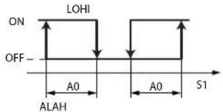
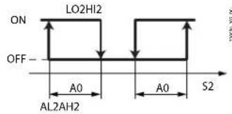
| Ref. Description |
| LO, LO2 Low temperature alarms |
| HI, HI2 High temperature alarms |
| S1, S2 Probes |
Fig. 10.b
Low evaporation pressure alarm (LP)
A low evaporation pressure (LP) alarm can be configured that stops the unit when the evaporation pressure falls below the threshold LPt for a settable time.
Activation of the alarm can be differentiated between steady operation (LPE) and at compressor start-up (LPS), so as to manage any transients when the compressor starts.
The type of alarm reset (LPr) can also be selected between manual and semi-automatic. When the alarm is activated, the message LP is shown on the display and in Applica, and the unit is stopped. For semi-automatic reset, the alarm is cleared when the evaporation pressure rises above the threshold LPt+LPU, with a maximum number of events equal to LPo in the evaluation period LPP. Once the maximum number of events has been exceeded, the alarm requires manual reset.
| Code Description Def Min Max UOM User User term. | |||||||
| LPE | Low evaporation pressure alarm delay in steady operation | 5 | 0 | 999 | s | M, S | No |
| LPo | Maximum number of automatic resets before switching to manual reset | 5 | 2 | 10 | - | M, S | No |
| LPP | Semi-automatic alarm reset attempt evaluation period | 60 | 1 | 9999 | Min | M, S | No |
| LPr | Low evaporation pressure alarm resetFALSE = Manual,TRUE = Semi-automatic | FALSE | FALSE | TRUE | - | M, S | No |
| LPS | Low evaporation pressure alarm delay at start-up | 30 | 0 | 999 | s | M, S | No |
| LPt | Low evaporation pressure alarm activation threshold | -1.0 | -1.0 | 20.0 | barg/psig | M, S | No |
| LPU | Low evaporation pressure alarm differential | 0.2 | 0.0 | 20.0 | barg/psig | M, S | No |
Tab. 10.e
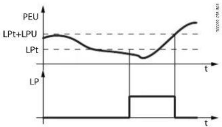
Fig. 10.c
High discharge pressure alarm (HP)
A high discharge pressure (HP) alarm can be configured to stop the unit when the discharge pressure exceeds the threshold HPt. Activation of the HP alarm immediately stops the unit, with the message HP shown on the display and in Applica.
The type of alarm reset (HPr) can also be selected between manual and semi-automatic. For semi-automatic reset, the alarm is cleared when the discharge pressure falls below the threshold HPt-HPU, with a maximum number of events equal to HPo in the evaluation period HPP. Once the maximum number of events has been exceeded, the alarm requires manual reset.
| Code Description Def Min Max UOM User User term. | |||||||
| HPo | Maximum number of automatic resets before switching to manual reset | 5 | 2 | 10 | - | M, S | No |
| HPP | Semi-automatic alarm reset attempt evaluation period | 60 | 1 | 9999 | Min | M, S | No |
| HPr | High discharge pressure alarm resetFALSE = Manual,TRUE = Semi-automatic | FALSE | FALSE | TRUE | - | M, S | No |
| HPt | High discharge pressure alarm activation threshold | 22.5 | -1.0 | 200.0 | barg/psig | M, S | No |
| HPU | High discharge pressure alarm differential | 1.5 | 0.0 | 20.0 | barg/psig | M, S | No |
Tab. 10.f
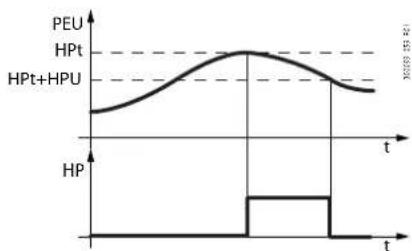
line
| t | HP | |-------|-------| | 0.0 | 0.0 | | 0.25 | 0.0 | | 0.5 | 1.0 | | 0.75 | 0.5 | | 1.0 | 0.0 |Fig. 10.d
Enable valve alarm at end travel ('blo')
Parameter P14 is used to enable/disable the valve blocked alarm signal ("blo").
| Code | Description | Def | Min | Max | UOM | User | User term. |
| P14 Enable valve alarm at end travel ("blo") | 1 | 0 | 1 | - | M N | ||
| 1 = signal enabled | |||||||
Tab. 10.g
10.6 HACCP alarms
(HACCP = Hazard Analysis and Critical Control Point).
Specific alarms for controlling the operating temperature, recording any anomalies due to power failures or an increase in the temperature due to other causes (breakages, extreme operating conditions, user errors, etc.).
Two types of potentially critical HACCP events are managed:
- type HA alarms, high temperature during operation;
example:
The critical temperature was exceeded, the alarm was not managed and the temperature remained above the threshold for longer than the maximum tolerable time (thresholds defined by site HACCP procedures). The event is critical and potentially hazardous.
- type HF alarms, high temperature after power failure;
example:
The unit was powered off. When restarted, the temperature is above the threshold and does not return to an acceptable level within an appropriate time (parameters defined by site HACCP procedures). The event is critical and potentially hazardous.
When an alarm occurs, the HACCP LED flashes, the display shows the alarm code, the alarm is logged and the alarm relay and buzzer are activated.
10.6.1 Parameters and monitoring activation
Type HA alarms
The type HA alarm is generated if during normal operation the temperature read by the probe set for parameter AA exceeds the high temperature threshold for the time Ad+Htd.
Consequently, compared to the normal high temperature alarm already signalled by the controller, the type HA HACCP alarm is delayed by a further time Htd specifically for HACCP recording.
| Code | Description | Def | Min | Max | UOM | User | User term. |
| Htd HA | ECP alarm delay0 = monitoring disabled | 0 0 240 | min | M, S, | J No | ||
| Han(*) | HACCP - number of HA alarms recorded | - | M, S, U | No |
Tab. 10.h

line
| Time | Signal | |------|--------| | 0 | AH | | 1 | St | | 2 | ON | | 3 | OFF | | t | AH | | t | ST | | t | ON | | t | OFF | | t | AH | | t | ST | | t | ON | | t | OFF |Fig. 10.e
| Ref. | Description |
| S | Measurement probe |
| St | Set point |
| AH | Low temperature alarm threshold |
| ALARM Type | HA HACCP alarm |
| Ad | Delay time for high and low temperature alarms |
| Htd | HACCP alarm delay - 0 = monitoring disabled |
| t | Time |
Type HF alarms
The type HF HACCP alarm is generated following a power failure for an extended time (>1 minute), if when power returns the temperature read by probe set for parameter AA exceeds the AH high temperature threshold. HFn indicates the number of type HF alarms activated.
| Code | Description | Def | Min | Max | UOM | User | User term. |
| HFn(*) | HACCP - number of HF alarms recorded | - | M,S,U | No |

line
| Time | Value | |------|-------| | t | AH | | t | St | | t | ON | | t | OFF | | t | Black out |Fig. 10.f
| Ref. | Description |
| S | Measurement probe |
| St | Set point |
| AH | Low temperature alarm threshold |
| ALARM Type | HA HACCP alarm |
| t | Time |
(*) Parameters visible to supervisor and APPLICA.
Notes
CAREL
CAREL INDUSTRIES - Headquarters
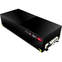
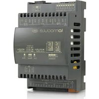
- USER MANUAL
- GENERAL WARNINGS
- INFORMATION FOR USERS ON THE CORRECT HANDLING OF WASTE ELECTRICAL AND ELECTRONIC EQUIPMENT (WEEE)
- Key to the symbols:
- Index
- Warnings....7
- Introduction 8
- Installation 12
- User interface....30
- Menu description 33
- Checks before commissioning 33
- Commissioning....34
- Functions....38
- Parameter table 72
- Alarms and signals....80
- WARNINGS
- General warnings
- Fundamental safety rules
- INTRODUCTION
- Main functions and features
- Overview:
- Components
- Control
- Applica
- Configuration and commissioning software
- User terminal (technical leaflet +050002915)
- Cable and connector kit
- Compressor (P/N ZCBQFC\*\*\*V0\*\*, manual +030222170 available on ksa.carel.com)
- Unipolar valve kit (P/N HZE01\*\*\*\*\*)
- USB/RS485 converter (P/N CVSTDUMOR0 technical leaflet +050000590)
- INSTALLATION
- Heosone system
- Functional diagrams
- Warnings
- Notice:
- Controller
- Warnings
- Dimensions - mm(in)
- Drilling template and assembly
- Cooling
- Caution:
- Electrical installation
- Conformity to EMC standards
- Electrical connections
- Power supply
- Compressor
- Compressor electrical connections
- Fans
- Bottle cooler
- Leakage current
- Compressor protection - safety digital input
- Serial network connection
- Rated current values
- User terminal
- Dimensions
- Installation
- Preliminary operations
- Removing the frame
- Panel mounting
- Front:
- Removal
- Electrical connections
- Technical specifications
- Compressor
- Structure
- Dimensions - mm
- Warnings
- E2V unipolar valve
- Dimensions
- Installation
- Technical specifications (E2V\*\*FSAC\*)
- Pressure probe (SPKT00\*\*P0)
- Dimensions/positioning
- Electrical connections
- Temperature probes
- Dimensions (NTC\*HP\*)/positioning
- NTC\*HP\* technical specifications
- NTC\*HF\* dimensions
- NTC\*HF\* technical specifications
- General connection diagram
- USER INTERFACE
- Introduction
- User terminal
- Key
- Keypad
- Display
- Standard display
- Programming mode
- Procedure (from user terminal)
- Direct functions
- MENU DESCRIPTION
- Menu tree
- CHECKS BEFORE COMMISSIONING
- COMMISSIONING
- User terminal
- Procedure:
- Mobile device
- Mobile device
- Procedure (modify parameters):
- Computer
- FUNCTIONS
- Inputs and outputs
- Probes (analogue inputs)
- Assign probe functions (parameters /FA, /Fb, /Fc, /Fd, /Fe)
- Calibration (parameters /cA, ... /cy)
- /2: analogue probe measurement stability
- Digital inputs
- Immediate external alarm (par. DIA)
- Delayed external alarm (par. Dlb)
- Enable defrost (par. Dlc)
- Start defrost (par. Dld)
- Door switch with stopping control (par. DIE)
- Door open:
- Door closed:
- Remote ON/OFF (par. DIF)
- Curtain switch (par. DIG)
- During night status:
- During day status:
- Start/stop continuous cycle (par. DIH)
- Digital input monitoring (par. DII)
- Timed input (timer) (par. DIL)
- Special features:
- Switch to Standby status (par. DIM)
- Switch to Clean status (par. Dln)
- Door switch without stopping control (par. DIP)
- Start/stop defrost from digital input (par. Dlr)
- Analogue outputs
- Digital outputs
- Alarm (par. DOb)
- Auxiliary (par. DOc)
- Light (par. DOE)
- Defrost (par. DOG)
- Evaporator fans (par. DOI)
- Condensate drain heater (par. DOP)
- Anti-sweat heater (par. DOQ)
- Generic stage function (par. DOS)
- Evaporator fans (par. DOt)
- Hot gas defrost solenoid (par. DOAA)
- Control
- Introduction
- Minimum and maximum set point values (parameters r1 and r2)
- Night-time operation
- Weighted control
- ON/OFF (par. ON)
- Example:
- ON time for duty setting operation (par. c4)
- Continuous cycle (parameter cc)
- Defrost priority over continuous cycle
- Defrost
- Introduction
- Heater defrost (d0 = 0, 2, 4): duty cycle
- Hot gas defrost (d0=1, 3)
- Advanced parameters
- Maximum interval between consecutive defrosts (dl, d1s)
- Staggered defrosts
- End defrost by timeout signal (par. r3)
- Defrost at power on (par. d4)
- Defrost delay at power on (parameter d5)
- Dripping time after defrost (par. dd)
- Valve positioning during defrost (par. dSb)
- Running time defrost (par.d10, d11)
- Sequential stops (par.dS1, dS2)
- Skip defrost (par. d7, dn)
- Power defrost (par. ddt, ddP)
- Evaporator fans
- Fixed-speed fans
- Fig. 8.m
- Variable-speed fans (EC fans)
- Condenser fans
- EC fan calibration (auto-tuning): introduction
- EC fan calibration procedure (FAT=1)
- • PHASE 1: maximum PWM signal calibration
- - PHASE 2: PWM signal calibration across the range of modulation
- Anti-sweat heater or fan modulation
- PI control
- Inputs
- Outputs
- Fixed activation control (manual control)
- Electronic valve
- Introduction
- Description of operation
- Superheat set point (parameter P3)
- Initial valve position when control starts (parameter cP1)
- Initial valve position maintenance time after defrost (parameter Pdd)
- PID control (parameters P4, P5, P6)
- Protection functions
- LowSH: low superheat threshold (par. P7)
- MOP: Maximum evaporation pressure
- LSA - Low suction temperature
- LOP Minimum evaporation pressure
- Manual valve positioning
- Read-only variables
- Compressor
- Switching on and off
- Fig. 8.y
- Pump down
- Generic functions
- Enabling
- Assign control probe
- On/Off output
- Modulating output
- Alarm signal
- Example
- PARAMETER TABLE
- Parameter table
- ALARMS AND SIGNALS
- Signals
- Types of alarms
- Active alarms
- Display alarm log
- Alarm table
- Alarm parameters
- High and low temperature alarms
- Low evaporation pressure alarm (LP)
- High discharge pressure alarm (HP)
- Enable valve alarm at end travel ('blo')
- HACCP alarms
- Parameters and monitoring activation
- Type HA alarms
- Type HF alarms
- Notes
- CAREL
Brand : Carel
Model : Heosone
Category : Uncategorized