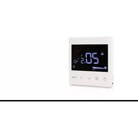
thTx - Climate control Carel - Free user manual and instructions
Find the device manual for free thTx Carel in PDF.


| Product Type | Room air regulator (thermostat) |
| Brand | Carel |
| Model | thTx (TDB001AAF0, TDC001AAF0, etc.) |
| Category | Climate control |
| Power supply | 85-260 VAC (TDB models) or 24 VAC/DC (TDC models) |
| Power consumption | < 1 W |
| Temperature sensor | Built-in, accuracy ±0.5°C |
| Humidity sensor | Built-in on select models, accuracy ±5% RH |
| Communication | RS485, Modbus RTU protocol (8 bits, 2 stop bits, no parity by default) |
| Max number of devices | 32 on an RS485 network |
| Fan speed | 3 manual speeds (Low, Medium, High) + automatic |
| Operating modes | Cooling, Heating, Ventilation |
| Temperature setpoint range | 5°C to 37°C (adjustable) |
| Humidity setpoint range | 50% to 70% RH (models with humidity) |
| Temperature differential | 0.0 to 5.0°C (adjustable) |
| Humidity differential | 1% to 20% (adjustable) |
| Anti-freeze protection | Yes, activation at 5°C, deactivation at 8°C |
| Screen lock | Yes, by pressing both arrow keys simultaneously for 3 seconds |
| Buzzer | Yes, can be enabled via parameter |
| Protection rating | IP20 |
| Overvoltage category | III |
| Dimensions (flush mounting) | Junction box diameter ≥ 65 mm, depth ≥ 35 mm |
| Weight | Approximately 0.2 kg |
| Warranty | 2 years (excluding consumables) |
| Standards | ISO 9001, UL94-V0 |
Frequently Asked Questions - thTx Carel
User questions about thTx Carel
0 question about this device. Answer the ones you know or ask your own.
Ask a new question about this device
Download the instructions for your Climate control in PDF format for free! Find your manual thTx - Carel and take your electronic device back in hand. On this page are published all the documents necessary for the use of your device. thTx by Carel.
USER MANUAL thTx Carel
ITA Manuale d'uso
ENG User manual
FRE Mode d'emploi
GER Technisches Handbuch
SPA Manual del usuario

AVVERTENZE GENERALI

natural_image
Two technical illustrations of electronic devices: a front panel with control buttons and a 3D model of a device on a base (no text or symbols visible)Fig. 1.a
1.2 Dimensioni
natural_image
Illustration of a hand using a screwdriver to adjust a small electronic device with a grid-patterned top (no text or symbols visible)- Setpoint cooling (
- Setpoint heating (
| Temperatura (Coil 70 = 0) | Umidità (Coil 70 = 1) | ||||
| Cool (HR140 = 3) Heat (HR140 = 4) | |||||
| OFF ON OFF ON OFF ON | |||||
| Relè APERTO Relè CHIUSO Relè APERTO Relè CHIUSO Relè APERTO Relè CHIUSO | |||||
Cool On = ON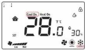 | Heat On = OFF | Heat On = ON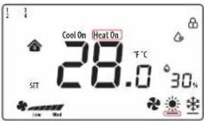 | water drop Icon= OFF | water drop Icon= ON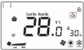 | |
Tab. 2.c

CAREL bases the development of its products on decades of experience in HVAC, on continuous investments in technological innovations to products, procedures and strict quality processes with in-circuit and functional testing on 100% of its products, and on the most innovative production technology available on the market. CAREL and its subsidiaries/affiliates nonetheless cannot guarantee that all the aspects of the product and the software included with the product respond to the requirements of the fi nal application, despite the product being developed according to start-of-the-art techniques. The customer (manufacturer, developer or installer of the fi nal equipment) accepts all liability and risk relating to the confi guration of the product in order to reach the expected results in relation to the specifi c fi nal installation and/or equipment. CAREL may, based on specifi c agreements, act as a consultant for the successful commissioning of the fi nal unit/application, however in no case does it accept liability for the correct operation of the fi nal equipment/system. The CAREL product is a state-of-the-art product, whose operation is specifi ed in the technical documentation supplied with the product or can be downloaded, even prior to purchase, from the website www.carel.com. Each CAREL product, in relation to its advanced level of technology, requires setup/confi guration/programming/commissioning to be able to operate in the best possible way for the specifi c application. Failure to complete such operations, which are required/indicated in the user manual, may cause the fi nal product to malfunction; CAREL accepts no liability in such cases. Only qualifi ed personnel may install or carry out technical service on the product. The customer must only use the product in the manner described in the documentation relating to the product.
In addition to observing any further warnings described in this manual, the following warnings must be heeded for all CAREL products:
- Prevent the electronic circuits from getting wet. Rain, humidity and all types of liquids or condensate contain corrosive minerals that may damage the electronic circuits. In any case, the product should be used or stored in environments that comply with the temperature and humidity limits specified in the manual.
- Do not install the device in particularly hot environments. Too high temperatures may reduce the life of electronic devices, damage them and deform or melt the plastic parts. In any case, the product should be used or stored in environments that comply with the temperature and humidity limits specified in the manual.
- Do not attempt to open the device in any way other than described in the manual.
- Do not drop, hit or shake the device, as the internal circuits and mechanisms may be irreparably damaged.
- Do not use corrosive chemicals, solvents or aggressive detergents to clean the device.
- Do not use the product for applications other than those specified in the technical manual.
All of the above suggestions likewise apply to the controllers, serial cards, programming keys or any other accessory in the CAREL product portfolio. CAREL adopts a policy of continual development. Consequently, CAREL reserves the right to make changes and improvements to any product described in this document without prior warning. The technical specifications shown in the manual may be changed without prior warning. The liability of CAREL in relation to its products is specified in the CAREL general contract conditions, available on the website www.carel.com and/or by specific agreements with customers; specifically, to the extent where allowed by applicable legislation, in no case will CAREL, its employees or subsidiaries/affiliates be liable for any lost earnings or sales, losses of data and information, costs of replacement goods or services, damage to things or people, downtime or any direct, indirect, incidental, actual, punitive, exemplary, special or consequential damage of any kind whatsoever, whether contractual, extra-contractual or due to negligence, or any other liabilities deriving from the installation, use or impossibility to use the product, even if CAREL or its subsidiaries/affiliates are warned of the possibility of such damage.

Fig. 1
Fig. 2
INFORMATION FOR USERS ON THE CORRECT HANDLING OF WASTE ELECTRICAL AND ELECTRONIC EQUIPMENT (WEEE)
With reference to European Union directive 2012/19/EU issued on 4 July 2012 and related national legislation, please note that:
- WasteElectricalandElectronicEquipment(WEEE)cannotbe disposedof as municipal waste but must be collected separately so as to allow subsequent recycling, treatment or disposal, as required by law;
- users are required to take Electrical and Electronic Equipment (EEE) at end-of-life, complete with all essential components, to the WEEE collection centres identified by local authorities. The directive also provides for the possibility to return the equipment to the distributor or retailer at end-of-life if purchasing equivalent new equipment, on a one-to-one basis, or one-to-zero for equipment less than 25 cm on their longest side;
- this equipment may contain hazardous substances: improper use or incorrect disposal of such may have negative effects on human health and on the environment;
- the symbol (crossed-out wheeled bin – Fig.1) even if, shown on the product or on the packaging, indicates that the equipment must be disposed of separately at end-of-life;
- If at end-of-life the EEE contains a battery (Fig. 2), this must be removed following the instructions provided in the user manual before disposing of the equipment. Used batteries must be taken to appropriate waste collection centres as required by local regulations;
- in the event of illegal disposal of electrical and electronic waste, the penalties are specified by local waste disposal legislation.
Warranty on materials: 2 years (from production date, excluding consumables).
Approval: the quality and safety of CAREL INDUSTRIES Hq products are guaranteed by the ISO 9001 certified design and production system.

separate as much as possible the probe and digital input cables from cables to inductive loads and power cables, so as to avoid possible electromagnetic disturbance. Never run power cables (including the electrical panel cables) and signal cables in the same conduits
Content
1. GENERAL FEATURES 7
1.1 Models 7
1.2 Dimensions....7
1.3 Assembly and connections 7
2. USING THE TERMINAL 9
2.1 Display and touch buttons 9
2.2 RS485 address setting 9
2.3 Using the terminal 9
3. TECHNICAL SPECIFICATIONS 12
1. GENERAL FEATURES
thTx is the CAREL room thermostat for residential or commercial environments, offering an easy-to-use interface.
The temperature is set simply and intuitively using the arrows on the touch keypad. The compact dimensions and elegant design make it suitable for any type of environment, as well as being ideal both as a user interface (HMI) for heat pumps, rooftop units, AHUs, fan coils, etc., and as a zone control display for centralised systems. The RS485 serial connection via Modbus® protocol can manage multiple thTx devices connected to the same programmable controller, for synergistic control. The thermostat can work in stand-alone mode as a room thermostat, or can be connected to programmable controllers for zone management in radiant systems. Depending on the model, it can be equipped with a temperature probe or a temperature and humidity probe, and is available with 230 Vac or 24 Vac/Vdc power supply. thTx can also manage a three-speed fan.
1.1 Models
FLUSH MOUNTING part numbers:
| P/N Model | |
| TDB001AAF0 85 | -260 VAC, temperature sensor only |
| TDC001AAF0 24 | VDC/AC, temperature sensor only |
| TDB001ACF0 85 | -260 VAC, temperature and humidity sensor |
| TDC001ACF0 24 | VDC/AC, temperature and humidity sensor |
Tab. 1.a

natural_image
Line drawing of a rectangular electronic device with control buttons (no text or symbols)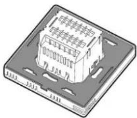
natural_image
3D illustration of a rectangular electronic component with internal slots and mounting holes (no text or symbols)Fig. 1.a
1.2 Dimensions
Dimensions for flush mounting
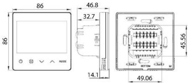
Fig. 1.b
Rear dimensions (mm)
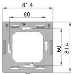
Fig. 1.c
1.3 Assembly and connections
Installation warnings
- The thTx thermostats have been designed for flush mounting, in wall boxes compatible with the standards in force;
- before carrying out any operations on the thermostat, disconnect the device from the power supply using the main switch on the electrical panel (OFF position). Then detach the front part of the thermostat from the rear part to make the electrical connections.

Notice: the thermostat should be installed indoors, at a height of approximately 1.5 m above the floor, in a place representing the average temperature. It should be away from direct sunlight, any coverings by heat source, to avoid false readings for temperature control.
natural_image
Diagram of a device with a switch inserted into a housing, showing internal components and wiring (no text or symbols)Fig. 1.d
Electrical connections
230 V/230V version
TDB001AAF0,TDB001ACF0
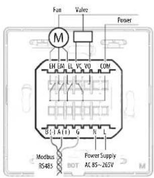
Fig. 1.e
24 V/24 V version
TDC001AAFO, TDC001ACFO
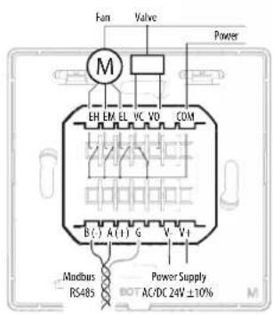
Fig. 1.f
Serial interface
RS485 serial interface for communication with the controllers. Use AWG 20 to 22 shielded wire. The total length of the network must not exceed 500 m. The power supply wires must be between 0.5 mm² and 1.5 mm². Up to 32 terminals can be connected. For large networks, place a 120 Ohm resistor between A (RX/TX+) and B (RX/TX-) on the last device, to avoid possible communication problems.
Exploded view
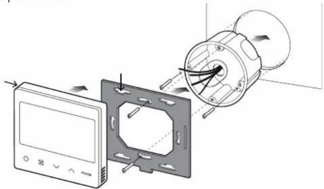
natural_image
Diagram showing a device with a control panel and a mechanical component, no text or symbols present.Fig. 1.g
Disassembly
Insert a screwdriver into the groove on the bottom and press outwards to detach the display.

General notes
Avoid installing the device in environments with the following characteristics:
• relative humidity higher than the specified value;
• strong vibrations or knocks;
- exposure to water sprays;
- exposure to aggressive and polluting atmospheres (e.g.: sulphur and ammonia gases, saline mist, smoke) which may cause corrosion and/or oxidation;
- strong magnetic and/or radio frequency interference (thus avoid installation near transmitting antennae);
- exposure to direct sunlight and the elements in general;
- wide and rapid fluctuations in room temperature;
• environments where explosives or flammable gas mixtures are present;
- exposure to dust (formation of corrosive patina with possible oxidation and reduction of insulation).
thTx 24 Vac/dc network configuration
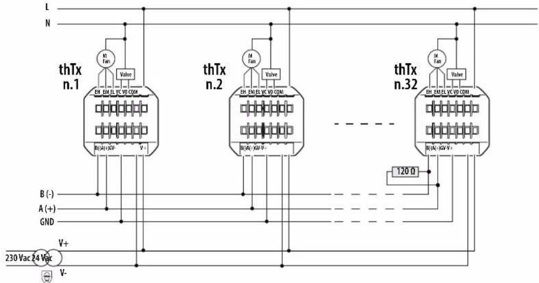
Fig. 1.h
thTx 230 Vac network configuration
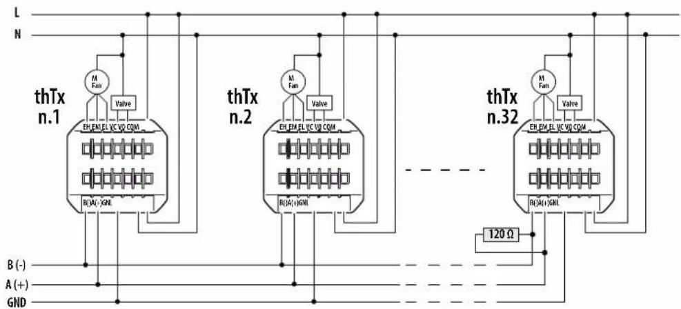
Fig. 1.i
2. USING THE TERMINAL
2.1 Display and touch buttons
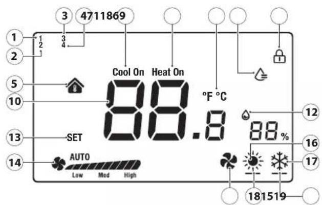
Fig. 2.a
| 1 | Humidify logic activated |
| 2 | Manual logic via RS485 active (relay) |
| 3 | Manual logic via RS485 active (mode) |
| 4 | Manual logic via RS485 active (fan) |
| 5 | Indoor temperature |
| 6 | Relay closed in cooling mode |
| 7 | Relay closed in heating mode |
| 8 | Display lock activated |
| 9 | Relay closed in humidify mode |
| 10 | Temperature |
| 11 | Temperature unit of measure |
| 12 | Relative humidity |
| 13 | Temperature setting |
| 14 | Fan speed in manual/automatic mode |
| 15 | Operating mode; Ventilation |
| 16 | Operating mode: Heating |
| 17 | Operating mode: Cooling |
| 18 | Relay closed in heating mode |
| 19 | Relay closed in cooling mode |
Functions of the buttons
| Button | Description | Function |
| Flashing ON/OFF | Press and hold for a few seconds to switch the thermostat on or off. When off, all the outputs will be open. | |
| Fan/Confirm | When the thermostat is on, press this button to set the fan speed to Low →Medium →High →Automatic fan speed →OffInside the menus or when changing the SET point, this becomes the "confirm" button | |
| Arrow Up/Down | When the thermostat is on, touch the Up or Down button to increase or decrease the set temperature, with 0.5 degree increments.After setting, press Fan/Confirm to save the new temperature or wait 8 seconds without touching any button to save the value automatically.When the thermostat is in normal operation, pressing the two buttons together for 3 seconds locks the display, with the padlock icon shown.Pressing the two buttons together again unlocks the display and the padlock icon is cleared. | |
| MODE | MODE | Select the operating mode: press until reaching the desired operating mode, between Cooling/I leating/Fan-only |
Tab. 2.a
The parameters and outputs can be set on the terminal in two possible ways: either directly on the display (using the buttons and parameters shown in Table 3.b) or via Modbus, setting the parameters shown in Table 3.c.
2.2 RS485 address setting
Select parameter E5 (communication address) to set and confirm the thermostat's RS485 serial address.
Up to 32 thermostats can be connected. The serial address must be in the range 1 to 207 (default address = 1).
This parameter can be set via Modbus variable HR 249.

Notice: the settings via Modbus do not require a reboot and take it immediately.
Communication modes
Protocol type: RTU
Data bits: 8
Stop bits: 2
Parity: None
Settable via menu E25 (stop bits) E26 (parity) or via Modbus variables HR340 and HR 341 respectively.

Notice: the settings via Modbus do not require a reboot and take it immediately.
BMS data transmission speed
Access menu parameter E24 (baud rate) and confirm the value:
• 0=19200 (default)
· 1=9600
• 2=4800
This parameter can be set via Modbus variable HR 250.

Notice: the settings via Modbus do not require a reboot and take it immediately.
2.3 Using the terminal
Setting the parameters
To access the menu for setting the parameters, switch the thermostat off using the ON/OFF button, press and hold
"MODE

for 5 seconds, then enter the password (0022).
Subsequently, the password can be changed using menu parameter E23. The complete list of parameters is shown in Table 3.b
Setting the mode
To set the operating mode, press the Mode button, the icon at the bottom left will change to Heating (sun) / Cooling (snowflake) / Ventilation (fan). The mode can also be viewed via Modbus parameter HR140
SET/FAN button
The button is used to change the fan speed and therefore the output (EL/EM/EH) of the three-speed fan. It is also used to confirm the settings (set point and in the settings menu).
Pressing
Pressing also selects the desired speed (low, med, high) or automatic (Auto), with the same setting sent via Modbus (register 141)
Switching the thermostat off and on (ON/OFF)
The thermostat can be switched off and on both directly on the thermostat, or via Modbus.
To switch it on, press ; press again to switch the thermostat off and deactivate the relay.
The thermostat is switched off and on via Modbus register HR143 (0 = OFF, 1 = ON).
Enabling the buzzer
To manage the buzzer, access menu parameter E4 (enable buzzer) and confirm:
- 0 = Disabled;
- 1 = Enabled;
Lock keypad
When the thermostat is in normal operation, press Up & Down for 3 seconds to lock the display, with the padlock icon shown. The same can be done via Modbus, setting variable HR165.
Relay control
Relay control by the user is available in both cooling and heating modes.
- Cooling set point (

- Heating set point (

Parameter dF (differential) in the parameters menu defines the differential in both heating and cooling mode. The set point must be set by the user. In addition to managing cooling and heating, the relay can also be used for humidity control, via menu parameter E28.
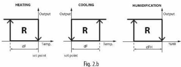
Set point
Switch on the thermostat, use the up arrow to increase the set point, or use the down arrow key to decrease it, 0.5 degrees at a time. The temperature can also be set via Modbus variable HR144.

Notice: the maximum and minimum set point value can be limited. A bles HR145 and HR146 and menu parameters E6 and E7.
The same thing applies when the relay is configured for managing Humidity mode, in which case the set point has increments/decrements of 1% RH; the set point value can also be set via Modbus variable HR 134.

Notice: the maximum and minimum set point value can also be used via Modbus variables HR152 and HR153 and menu parameters and E23.
Diff erential
To set the Temperature differential, access menu parameter E19, while for Humidity access menu parameter E21. The increment for the temperature differential (HR58) is 0.1, from 0.0 to 5.0. The increment for the Humidity differential (HR50) is 1, from 0 to 20.
Humidity control
In models fitted with a humidity probe, the data is displayed next to the temperature value. The relative humidity value can also be read via Modbus register HR134.
Frost protection mode
This can be enabled by using menu parameter E10. Frost protection is only available during heating mode; when the temperature drops to 5.0°C, frost protection is activated, while when the temperature is above 8.0°C, frost protection is interrupted by the relay.
Alarm
When one of the following alarms is present, the error code is displayed on the LCD. Modbus coil 32 takes the value 1.
- if the error is on the temperature sensor, the LCD displays "E1", - if the error is on the humidity sensor, the LCD displays "E3".
Temperature sensor calibration
To adjust the temperature calibration, access menu parameter E8 (temperature
calibration); the range is between -9 and +9 °C, with
± 0.1 °C steps. The same configuration can be done via Modbus, setting variable HR10
Humidity sensor calibration
Available only on models with humidity sensor. To adjust the humidity calibration, access menu parameter E9 (humidity calibration); the range is -20 to +20 RH% with ± 0.1% RH steps. The same can be done via Modbus, setting variable HR57.
Manual mode
In addition to stand-alone mode whereby the thTx automatically manages the outputs based on the set point values and the confi guration, the display can also be operated via Modbus, overwriting the values and therefore completely managing the icons and related outputs.
To enable this mode, simply set the desired parameters via Modbus:
- Coil 51 is used to manually set the relay status (relay management configuration) [0=Automatic, thTx; 1=manual, via Modbus]
- Coil 59 is used set the MODE [0=Automatic, thTx; 1=manual, via Modbus]
- Coil 60 is used to configure the Fan [0=Automatic, thTx; 1=manual, via Modbus]
Management of the icons on the display
In the default configuration, the thTx can operate in Heating / Cooling / Ventilation mode; setting menu parameter E12 or Modbus register HR350, certain icons can be displayed, specifically:
0: The fan operates and is visible in both heating and cooling modes
| Mode Icon shown Ventilation ramp | Med | |
| YES YES | ||
| YES YES | ||
| YES YES |
1: The fan operates in cooling mode but is not visible in heating mode
| Mode Icon shown Ventilation ramp | ||
| YES NO | ||
| YES YES | ||
| YES YES | ||
2: The fan operates in heating mode but is not visible in cooling mode
| Mode Icon shown | Ventilation ramp | Med |
| YES YES | ||
| YES NO | ||
| YES YES |
3: The fan is not visible in either heating or cooling mode, but the fan mode is selectable
| Mode Icon shown | Ventilation ramp | |
| YES NO | ||
| YES NO | ||
| YES YES |
4: Heating and cooling modes only available (fan mode not visible)
| Mode Icon shown Ventilation ramp | ||
| YES NO | ||
| YES NO | ||
| NO NO | ||
Furthermore, by changing the value of variable COIL 59, MODE setting managed via Modbus RS485, icon 3 will be shown in the top left of the screen:
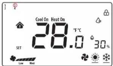
Fig. 2.c
Now set HR140 (S_MODE) to completely overwrite the MODE; setting the register to specific values will display the corresponding icon:
0x03: Cool (●);
0x04: Heat ( )
0x05: Ventilation (☐);
0x255: NO ACTIONS (all icons cleared); this setting allows the thTx to be used as a room probe only.
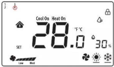
Fig. 2.d
Setting variable COIL 60, "Fan - button selection" managed via Modbus RS485, icon 4 will be shown in the top left of the screen:
Now set HR141 (S_FAN) to completely overwrite the fan speed; setting the register to specific values will display the corresponding icon:
0: all OFF (♣);
1: Fan_Speed1 (Low);
2: Fan_Speed1 + Speed2 ();
3: Fan_Speed1 + Speed2 + Speed3 (High);
255: Fan_Speed1 + Speed2 + Speed3 + Auto (♣ AUTO).
Notice: when the fan logic is managed independently by the thTx and the fan is set to AUTO, the device has two differentiated functions, depending on whether it is in cooling or heating mode.
Cooling mode Heating mode
- When the room temperature is ≥ the set temperature +1°C, the fan operates at low speed;
- When the room temperature is ≥ the set temperature +2°C, the fan operates at medium speed;
- When the room temperature is ≥ the set temperature +3°C, the fan operates at high speed;
-
When the room temperature ≤ the set temperature, the relay opens and the fan stops.
-
When the room temperature is ≤ the set temperature -1°C, the fan operates at low speed;
- When the room temperature ≤ the set temperature -2°C, the fan operates at medium speed;
- When the room temperature is ≤ the set temperature -3^ , the fan operates at high speed;
- When the room temperature is ≥ the set temperature, the relay opens and the fan stops.
Tab. 2.b
Notice: in ventilation mode, the fan speed has no relation to the set temperature.
Relay management
By setting variable COIL 51, "Relay management configuration" via Modbus RS485, icon 2 will be shown in the top left of the screen:
Depending on the confi guration set via coil 70 (or menu parameter E28) Management of relay outputs (0: Temperature = Temperature control 1: Humidity = Humidity control) and the MODE activated (HR140), the status of the relay can be controlled via COIL 52.
Summary of displays based on the configuration:
Manual (Coil 51 = 1)
| Temperature (Coil 70 = 0) | Humidity (Coil 70 = 1) | ||||
| Cool (HR140 = 3) Heat (HR140 = 4) | |||||
| OFF ON OFF ON OFF ON | |||||
| Relay OPEN Relay CLOSED Relay OPEN Relay CLOSED Relay OPEN Relay CLOSED | |||||
| Cool On = ON | Cool On = ON | Heat On = OFF | Heat On = ON | Water drop icon = OFF | Water drop icon = ON |
| Cool On = OFF | 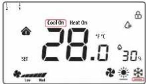 | 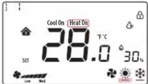 | 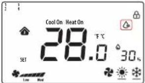 | ||
Tab. 2.c

Notice: the configurations can be combined for complete control of the icons.
3. TECHNICAL SPECIFICATIONS
| Power supply Models TDB******: 85~260 VAC 50/60 Hz | Models TDC******: 24 VAC/DC (+10 to -10%) |
| Operating conditions 0T55°C, 10 to <95% RH non-cond. | |
| Storage conditions -20T60 °C | |
| Environmental pollution | 2 |
| Software class and structure | A |
| Casing ingress protection | IP20 |
| Heat and fire resistance category | UL94-V0 |
| Class of protection against electric shock | to be incorporated in class I or II appliances |
| Period of electrical stress across the insulating parts | long |
| Immunity against surges | Category III |
| Temperature measurement accuracy | ±0.5 °C |
| Humidity measurement accuracy | ±5% rH |
| Max power consumption | < 1W |
| Resistive load | ≤ 3A |
| Maximum load current | 0.7 A |
Tab. 3.a
| No. | Description Range | Def. | Notes | |
| E01 | Reset data to factory values | 0÷99 | 53 Default: 53, set to 55 and select the MODE button | |
| E02 | Status after blackout | 0÷2 | 1 0: the display is OFF.1: the display shows the home screen.2: the display shows the last status before the blackout. | |
| E03 | Backlight in standby | 1÷5 | 4 - | |
| E04 | Buzzer | 0÷1 | 0 0: Mute 1: On | |
| E05 | Communication address | 1÷207 | 1 - | |
| E06 | Maximum temperature set point | 0°C÷99°C | 37°C - | |
| E07 | Minimum temperature set point | 0°C÷99°C | 5°C - | |
| E08 | Internal temperature calibration | -9÷9 | 0.0 - | |
| E09 | Internal humidity calibration | -20÷20 | 7 Notice: the display -20 shows -20°C not -2.0 | |
| E10 | Frost protection | ON/OFF | OFF ON: Frost prot. On; OF: Frost prot. OffRange: 5.0°C to 8.0°CFrost protection is only available during heating mode; when the temperature drops to 5.0°C, frost protection is activated, while when the temperature is above 8.0°C, frost protection is interrupted. | |
| E11 | Fan status when target temperature is reached | ON/OFF | OFF ON: Low speed OF: Fan off | |
| E12 | Fan operating mode | 0÷4 | 0 0: The fan operates and is visible in both heating and cooling modes1: The fan operates in cooling mode but is not visible in heating mode2: The fan operates in heating mode but is not visible in cooling mode3: The fan is not visible in either heating or cooling mode, but the fan mode is selectable4: Heating and cooling modes only available (fan mode not visible) | |
| E13 | Fan circulation function option | ON/OFF | OFF ON: Low speedOF: The fan is switched off | |
| E14 | Fan circulation time | 1÷30 (Minutes) | 5 (min) Set the fan circulation time per hour | |
| E15 | Temperature differential | 0÷5 | 0.5 | |
| E16 | Temperature unit of measure | 0÷1 | 0 0: °C1: °F | |
| E17 | Humidity differential | 1%÷20% | 5% - | |
| E18 | Maximum humidity set point | 0%÷99% | 70% - | |
| E19 | Minimum humidity set point | 0%÷99% | 50% - | |
| E20 | Serial port baud rate | 0÷3 | 2 0=4800 bps; 1=9600 bps;2=19200 bps; 3=38400 bps | |
| E21 | Serial port stop bits | 0÷1 | 1 0=1 stop bit; 1=2 stop bits | |
| E22 | Serial port control bits | 0÷2 | 0 0=None; 1 = Odd; 2 = Even | |
| E23 | Change menu password | 0000÷9999 | 0022 Range: 0000 to 9999 | |
| E24 | Relay output control | 0÷1 | 0 0: Temperature = Temperature control1: Humidity = Humidity control | |
Tab. 3.b
Summary table of operating parameters
| Address Type | R/W Description of the variables | Interpretation of the data | ||||
| Default Min Max | ||||||
| 4x0010 HR R/W Temperature probe calibration [°C] 0 -90*0.1 90*0.1 | ||||||
| 4x0050 HR R/W differential h 5 1 20 | ||||||
| 4x0057 IIR R/W Humidity sensor calibration [H%] 0 -20 20 | ||||||
| 4x0058 | HR | R/W | Differential t | 0.5 | 0 | 50*0.1 |
| 4x0129 | HR | R | Terminal firmware version | 0 | 0 | 65535 |
| 4x0130 | HR | R | Terminal hardware code | 0 | 0 | 65535 |
| 4x0133 | HR | R | Terminal internal probe temperature | 0 | -32768 | 32767 |
| 4x0134 | HR | R | Terminal internal probe humidity | 0 | 0 | 0 |
| 4x0140 | IIR | R/W | Value selected for the Mode function (Cool/I leat/Fan) | 0 | 0 | 255 |
| 4x0141 HR R/W Value selected for the Fan function 0 0 255 | ||||||
| 4x0143 | HR | R/W | Value selected for the Power On/Off function | 1 | 0 | 255 |
| 4x0144 | HR | R/W | Temperature set point value | 0 | HR 0x146 value | HR 0x145 value |
| 4x0145 | HR | R/W | Maximum temperature set point | 37.0 | 0 | 550*0.1 |
| 4x0146 | IIR | R/W | Minimum temperature set point | 5.0 | 0 | 550*0.1 |
| 4x0151 | HR | R/W | Humidity set point value | 55 | HR 0x153 value | HR 0x152 value |
| 4x0152 HR R/W Maximum humidity set point 70 | 0.99 | |||||
| 4x0153 HR R/W Minimum humidity set point 50 | 0.99 | |||||
| 4x0165 HR R/W LOCK | 0 0 | 65535 | ||||
| 4x0249 HR R/W Serial address | 1 1 | 207 | ||||
| 4x0250 HR R/W Baud rate | 2 0 | 3 | ||||
| 4x0253 | HR | R/W | Menu access password | 22 | 0 | 9999 |
| 4x0255 HR R/W Backlight brightness | 4 0 | 5 | ||||
| 4x0340 HR R/W Serial line stop bits | 1 0 | 1 | ||||
| 4x0341 HR R/W Serial line parity | 0 0 | 2 | ||||
| 4x0350 HR R/W Fan operating mode | 0 4 | 0 | ||||
| 4x0360 | HR | R/W | Temperature set point value | 0 | HR 0x146 value | HR 0x145 value |
| 4x0361 | HR | R/W | Temperature set point value | 0 | HR 0x146 value | HR 0x145 value |
| 0x0019 | Coil | R/W | UoM for temp. displayed (0°C 1°F) NO value conversion | 0 | 0 | 1 |
| 0x0032 | Coil | R | Generic alarm | 0 | 0 | 1 |
| 0x0051 | Coil | R/W | Relay management configuration | 0 | 0 | 1 |
| 0x0052 Coil | R/W Relay output | 0 0 | 1 | |||
| 0x0056 Coil | R/W Enable buzzer | 0 0 | 1 | |||
| 0x0059 | Coil | R/W | Select Mode button | 0 | 0 | 1 |
| 0x0060 | Coil | R/W | Fan - select button | 0 | 0 | 1 |
| 0x0070 | Coil | R/W | Relay output management | 0 | 0 | 1 |
Tab. 3.c
AVERTISSEMENTS

natural_image
Line drawing of a rectangular electronic device with control buttons (no text or symbols)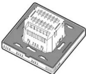
natural_image
Isometric illustration of a microchip with internal circuitry and mounting holes (no text or symbols)Fig. 1.a
1.2 Dimensions
natural_image
Illustration of a hand using a screwdriver to adjust a small electronic component (no text or symbols visible)natural_image
Diagram showing a device with a control panel and a mechanical component being inserted (no text or symbols present)Fig. 1.g
Démontage
 | |
| OUI NON | |
| OUI NON | |
| OUI OUI | |
natural_image
Two electronic device components: a front panel with control buttons and a back panel with internal circuitry (no text or symbols visible)Fig. 1.a
1.2 Abmessungen
natural_image
Illustration of a hand using a screwdriver to adjust a component on a base (no text or symbols visible)Fig. 1.d
Elektrische Anschlüsse
Version 230V
TDB001AAF0,TDB001ACF0
Version 24V
TDC001AAF0, TDC001ACF0
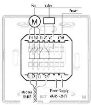
Fig. 1.e
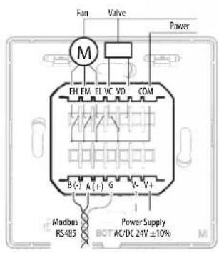
Fig. 1.f
Fig. 1.g
Demontage
Manuell (Coil 51 =1)
natural_image
Two technical illustrations of electronic devices: a front panel with control buttons and a 3D model of a device with internal components (no text or symbols visible)Fig. 1.a
1.2 Dimensiones
natural_image
Illustration of a hand inserting a screwdriver into a device component (no text or symbols visible)Fig. 1.g
Desmontaje
Manual (Coil 51 = 1)
| Temperatura (Coil 70 = 0) | Humedad (Coil 70 = 1) | ||||
| Cool (HR140 = 3) Heat (HR140 = 4) | |||||
| OFF ON OFF ON OFF ON | |||||
| Relé ABIERTO Relé CERRADO Relé ABIERTO Relé CERRADO Relé ABIERTO Relé CERRADO | |||||
Cool On = ON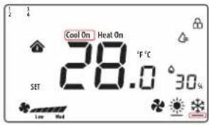 | Heat On = OFF | Heat On = ON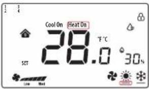 | water drop Icon= OFF | water drop Icon = ON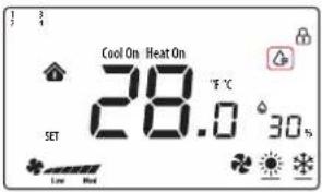 | |
Tab. 2.d

- AVVERTENZE GENERALI
- Dimensioni
- INFORMATION FOR USERS ON THE CORRECT HANDLING OF WASTE ELECTRICAL AND ELECTRONIC EQUIPMENT (WEEE)
- Content
- GENERAL FEATURES 7
- USING THE TERMINAL 9
- TECHNICAL SPECIFICATIONS 12
- GENERAL FEATURES
- Models
- Dimensions
- Assembly and connections
- Installation warnings
- Serial interface
- Disassembly
- General notes
- USING THE TERMINAL
- RS485 address setting
- Communication modes
- BMS data transmission speed
- Using the terminal
- Setting the parameters
- Setting the mode
- SET/FAN button
- Switching the thermostat off and on (ON/OFF)
- Enabling the buzzer
- Lock keypad
- Relay control
- Set point
- Diff erential
- Humidity control
- Frost protection mode
- Alarm
- Temperature sensor calibration
- Humidity sensor calibration
- Manual mode
- Management of the icons on the display
- Cooling mode Heating mode
- Relay management
- TECHNICAL SPECIFICATIONS
- Summary table of operating parameters
- AVERTISSEMENTS
- Démontage
- Abmessungen
- Demontage
- Dimensiones
- Desmontaje
Brand : Carel
Model : thTx
Category : Climate control