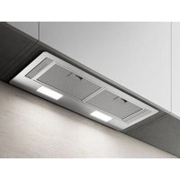
Maggiore EMG642S1 - Range hood ELICA - Free user manual and instructions
Find the device manual for free Maggiore EMG642S1 ELICA in PDF.

User questions about Maggiore EMG642S1 ELICA
0 question about this device. Answer the ones you know or ask your own.
Ask a new question about this device
Download the instructions for your Range hood in PDF format for free! Find your manual Maggiore EMG642S1 - ELICA and take your electronic device back in hand. On this page are published all the documents necessary for the use of your device. Maggiore EMG642S1 by ELICA.
USER MANUAL Maggiore EMG642S1 ELICA
natural_image
Isometric line drawing of a mechanical or electronic component with a central housing and mounting base (no text or symbols)Use, Care, and Installation Guide
READ AND SAVE THESE INSTRUCTIONS
LISEZ CES INSTRUCTIONS ET CONSERVEZ-LES
LEA Y CONSERVE ESTAS INSTRUCCIONES
LIB0143197 Printed in Mexico 05/18
ENGLISH
Contents
Important safety notice....4
Electrical & installation requirements 5
Before installing the hood 5
Dimensions and clearances.... 5
List of materials....6
Parts supplied 6
Parts not supplied 6
Ducting options and examples....7
Installation 7
Electrical connection.... 11
Complete the installation.... 11
Description of the hood....13
Control....13
Maintenance 15
Warranty 16
APPROVED FOR RESIDENTIAL APPLIANCES FOR RESIDENTIAL USE ONLY READ AND SAVE THESE INSTRUCTIONS
PLEASE READ ENTIRE INSTRUCTIONS BEFORE PROCEEDING. INSTALLATION MUST COMPLY WITH ALL LOCAL CODES.
IMPORTANT: Save these Instructions for the Local Electrical Inspector's use.
INSTALLER: Please leave these Instructions with this unit for the owner.
OWNER: Please retain these instructions for future reference.
Safety Warning: Turn off power circuit at service panel and lock out panel, before wiring this appliance. Requirement: 120 V AC, 60 Hz. 15 or 20 A Branch Circuit
IMPORTANT SAFETY NOTICE
I CAUTION
FOR GENERAL VENTILATING USE ONLY. DO NOT USE TO EXHAUST HAZARDOUS OR EXPLOSIVE MATERIALS OR VAPOURS.
I WARNING
TO REDUCE THE RISK OF FIRE, ELECTRIC SHOCK, OR INJURY TO PERSONS, OBSERVE THE FOLLOWING:
A. Use this unit only in the manner intended by the manufacturer. If you have questions, contact the manufacturer.
B. Before servicing or cleaning the unit, switch power off at service panel and lock service panel disconnecting means to prevent power from being switched on accidentally.
When the service disconnecting means cannot be locked, securely fasten a prominent warning device, such as a tag, to the service panel.
C. Installation work and electrical wiring must be done by qualified person(s) in accordance with all applicable codes & standards, including fire-rated construction.
D. Sufficient air is needed for proper combustion and exhausting of gases through the flue (Chimney) of fuel burning equipment to prevent back- drafting. Follow the heating equipment manufacturers guideline and safety standards such as those published by the national fire protection association (NFPA), the american society for heating, refrigeration and air conditioning engineers (ASHRAE), and the local code authorities.
E. When cutting or drilling into wall or ceiling, do not damage electrical wiring and other hidden utilities.
F. Ducted fans must always be vented to the outdoor.
I CAUTION
To reduce risk of fire and to properly exhaust air, be sure to duct air outside - do not vent exhaust air into spaces within walls, ceilings, attics, crawl spaces, or garages.
I WARNING
TO REDUCE THE RISK OF FIRE, USE ONLY METAL DUCT WORK.
Install this hood in accordance with all requirements specified.
I WARNING
To reduce the risk of fire or electric shock, do not use this hood with any external solid state speed control device.
I WARNING
TO REDUCE THE RISK OF A RANGE TOP GREASE FIRE.
a) Never leave surface units unattended at high settings. Boilovers cause smoking and greasy spillovers that may ignite. Heat oils slowly on low or medium settings.
b) Always turn hood ON when cooking at high heat or when flambeing food (i.e. Crepes Suzette, Cherries Jubilee, Peppercorn Beef Flambe').
c) Clean ventilating fans frequently. Grease should not be allowed to accumulate on fan or filter.
d) Use proper pan size. Always use cookware appropriate for the size of the surface element.
I WARNING
TO REDUCE THE RISK OF INJURY TO PERSONS, IN THE EVENT OF A RANGE TOP GREASE FIRE, OBSERVE THE FOLLOWING:
a) SMOTHER FLAMES with a close-fitting lid, cookie sheet, or other metal tray, then turn off the gas burner or the electric element. BE CAREFUL TO PREVENT BURNS. If the flames do not go out immediately, EVACUATE AND CALL THE FIRE DEPARTMENT.
b) NEVER PICK UP A FLAMING PAN - you may be burned.
c) DO NOT USE WATER, including wet dishcloths or towels - a violent steam explosion will result.
d) Use an extinguisher ONLY if:
1) You know you have a class ABC extinguisher, and you already know how to operate it.
2) The fire is small and contained in the area where it started.
3) The fire department is being called.
4) You can fight the fire with your back to an exit.
^a Based on "Kitchen Fire Safety Tips" published by NFPA.
OPERATION
Always leave safety grills and filters in place. Without these components, operating blowers could catch onto hair, fingers and loose clothing.
The manufacturer declines all responsibility in the event of failure to observe the instructions given here for installation, maintenance and suitable use of the product. The manufacturer further declines all responsibility for injury due to negligence and the warranty of the unit automatically expires due to improper maintenance.
I CAUTION
Automatically Operated Device - To reduce the risk of Injury disconnect from power supply before servicing.
ELECTRICAL & INSTALLATION REQUIREMENTS
IMPORTANT
Observe all governing codes and ordinances.
It is the customer's responsibility:
• To contact a qualified electrical installer.
- To assure that the electrical installation is adequate and in conformance with National Electrical Code, ANSI/NFPA 70 — latest edition*, or CSA Standards C22.1-94, Canadian Electrical Code, Part 1 and C22.2 No.0-M91-latest edition** and all local codes and ordinances.
- If codes permit and a separate ground wire is used, it is recommended that a qualified electrician determine that the ground path is adequate.
• Do not ground to a gas pipe.
- Check with a qualified electrician if you are not sure range hood is properly grounded.
- Do not have a fuse in the neutral or ground circuit.
IMPORTANT
- Save Installation Instructions for electrical inspector's use.
• The range hood must be connected with copper wire only. - The range hood should be connected directly to the fused disconnect (Or circuit breaker) box through metal electrical conduit.
- Wire sizes must conform to the requirements of the National Electrical Code ANSI/NFPA 70 — latest edition*, or CSA Standards C22.1-94, Canadian Electrical Code Part 1 and C22.2 No. O-M91 - latest edition** and all local codes and ordinances.
- A U.L.- or C.S.A.-listed conduit connector must be provided at each end of the power supply conduit (at the range hood and at the junction box).
BEFORE INSTALLING THE HOOD
1 For the most efficient air flow exhaust, use a straight run or as few elbows as possible.
CAUTION: Vent unit to outside of building, only.
2 At least two people are necessary for installation.
3 Fittings material is provided to secure the hood to most types of walls/ceilings, consult a Qualified Installer, check if they perfectly fit with your cabinet/wall.
4 Do not use flex ducting.
5 COLD WEATHER installations should have an additional backdraft damper installed to minimize backward cold air flow and a nonmetallic thermal break to minimize conduction of outside temperatures as part of the ductwork. The damper should be on the cold air side of the thermal break.
The break should be as close as possible to where the ducting enters the heated portion of the house.
6 Make up air: Local building codes may require the use of Make-Up Air Systems when using Ducted Ventilation
Systems greater than specified CFM of air movement.
The specified CFM varies from locale to locale. Consult your HVAC professional for specific requirements in your area.
Copies of the standards listed may be obtained from:
* National Fire Protection Association Batterymarch Park Quincy,
Massachusetts 02269
** CSA International 8501 East Pleasant Valley Road Cleveland,
Ohio 44131-5575
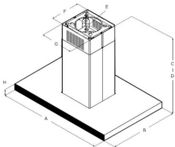
DIMENSIONS AND CLEARANCES
text_image
F E G H A B C D| Models | ||
| EMG636S1 EMG642S1 | ||
| A 36" (91.4 cm) 42" (106.7 cm) | ||
| B | 27 18 " (68.9 cm) | |
| C* | Min: 29 1316 " (75.7 cm)Max: 50 18 " (127.3 cm) | |
| D** | Min: 29 1316 " (75.7 cm)Max: 44 ^7_8 " (114 cm) | |
| E | 6" (15.9 cm) | |
| F | 12" (30.4 cm) | |
| G | 13" (33.24 cm) | |
| H | 2 38 " (6 cm) | |
* Ductless (Recirculating) version
** Ducted version
LIST OF MATERIALS
Removing the packaging.
I CAUTION
Remove carton carefully, Wear gloves to protect against sharp edges.
I WARNING
Remove the protective film covering the product before putting into operation.
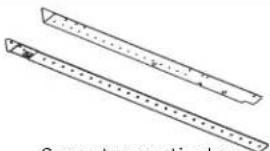
Supplied Part Pieces Supplied Part Pieces
 Hood assembly with blower and LED lamps already installed Hood assembly with blower and LED lamps already installed | 1 | 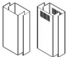 Lower and upper duct covers Lower and upper duct covers | Upper: 2Lower: 2 |
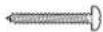 5x45 mm 5x45 mm | 4 | 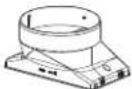 6" round air transition 6" round air transition | 1 |
 4.2X8 mm 4.2X8 mm | 60 |  Duct cover brackets Duct cover brackets | 4 |
 | 2 | 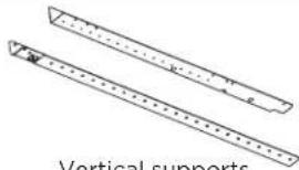 vertical supports vertical supports | Upper: 4Lower: 4 |
 | 4 | ||
 | 2 | ||
  | 2 |  Torx adapter Torx adapter | #10: 1#20: 1 |
| [4X26][C823] | 4 | 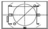 Mounting template Mounting template | 1 |
Parts no supplied
Tools/Materials required
- Wire nuts
- Tape to mount template
- 6" (15.2 cm) round metal duct length to suit installation
- Measuring tape
- Pliers
- Gloves
- Knife
- Safety glasses
• Electric drill with 516 " and 38 " bits - Strain relief
- Spirit level
- Duct tape
- Screwdrivers:
- Phillips (Posidrive) #2
- TORX #10, #20
- Wire cutter/stripper
- Masking tape
- Hammer
- Saw, jig saw or reciprocating saw
Optional accessories and consumable parts
| KIT # Part | |
| Recirculating Kit | KIT02665 |
| Long Chimney Extension | KIT0100317 |
| Charcoal Filter Replacement | KIT02667 |
Ducting options
Closely follow the instructions set out in this manual.
All responsibility, for any eventual inconveniences, damages or fires caused by not complying with the instructions in this manual, is declined.
Ducting version Ductless (Recirculating
The hood is equipped with a 6" (15.2 cm) round transition for discharge of fumes to the outside.
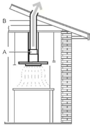
text_image
B AA. 6" round transition
B. 6" round duct
In cases where it should not be possible to discharge cooking fumes and vapour to the outside.
Attach a charcoal filter and the deflector on the duct cover support bracket.
Fumes and vapours are recycled through the top grille by means of a duct connected to the transition and the transition mounted on the deflector.
See accessories section.
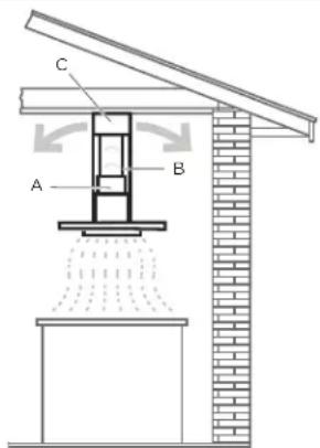
text_image
C A BA. 6" round transition
B. 6" round duct
C. Air deflector
Preparation
Do not cut a joist or stud unless absolutely necessary. If a joist or stud must be cut, then a supporting frame must be constructed.
Fittings material is provided to secure the hood to most types of walls/ceilings.
However, a qualified technician must verify suitability of the materials in accordance with the type of wall/ceiling.
Before making cutouts, make sure there is proper clearance within the ceiling or wall for exhaust vent.
Recommended installation height:
Hood installation height above cooktop is the users preference.
The lower the hood is above the cooktop, the more efficient the capturing of cooking odors, grease and smoke.
| CAUTION
Mount this hood so that the bottom edge above the cooking surface is at 30" (76.2 cm) minimum if a gas range is used, or at 24" (61 cm) if an electric range is used.
There is no maximum mounting height, however, we recommend mounting the hood no greater than 36" above the cooking surface. For every inch (2.54 Cm) above 36", fume and moisture capture efficiency
Diminishes at an increasing rate and may not deliver an acceptable level of ventilating performance.
This hood is intended for household use.
Please read the installation manual for specific application.
Check your ceiling height and hood height before selecting your hood.
Installation
Ceiling support structures
- This vent hood is heavy. Adequate structure and support must be provided in all types of installations.
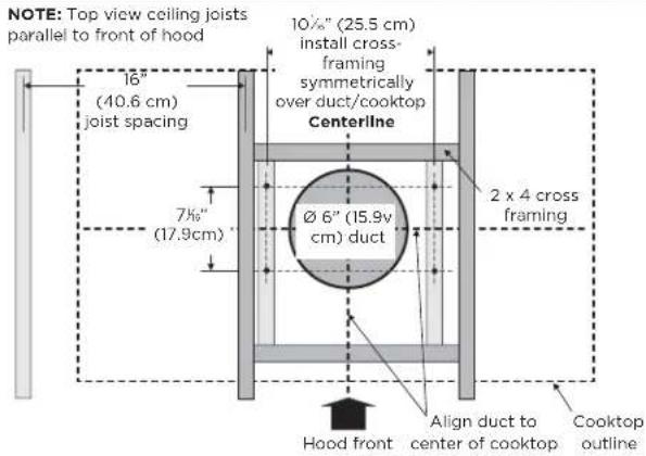
- At the hood location, install 2"x 4" cross framing between ceiling joists as shown (2"x 4" are required to support the weight of the hood).
- Arrange cross framing in the ceiling to suit the existing structure.
- Your ceiling joists will be like one of the following:
Example A
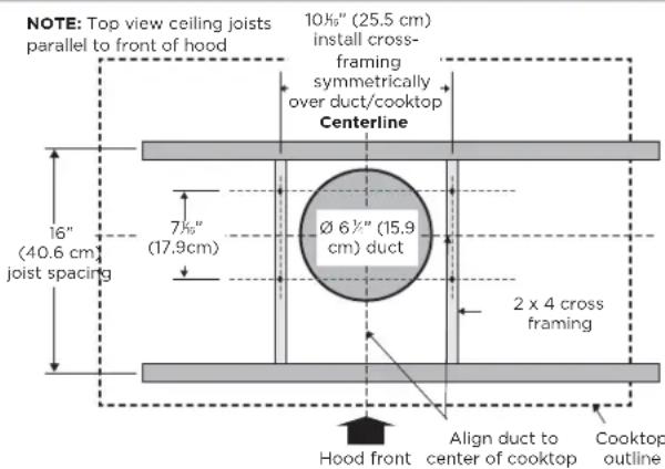
text_image
NOTE: Top view ceiling joists parallel to front of hood 10½" (25.5 cm) install cross- framing symmetrically over duct/cooktop Centerline 16" (40.6 cm) joist spacing 7½" (17.9cm) Ø 6½" (15.9 cm) duct 2 x 4 cross framing Hood front Align duct to center of cooktop Cooktop outlineExample B
text_image
NOTE: Top view ceiling joists parallel to front of hood 16" (40.6 cm) joist spacing 7½" (17.9cm) 10½" (25.5 cm) install cross-framing symmetrically over duct/cooktop Centerline Ø 6" (15.9v cm) duct 2 x 4 cross framing Hood front Align duct to center of cooktop Cooktop outlineExample C
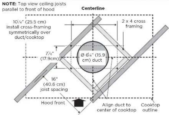
text_image
NOTE: Top view ceiling joists parallel to front of hood Centerline 10½" (25.5 cm) install cross-framing symmetrically over duct/cooktop 2 x 4 cross framing Ø 6/4" (15.9 cm) duct 7½" (17.9cm) 16" (40.6 cm) joist spacing Hood front Align duct to center of cooktop Cooktop outlineInstall Range Hood
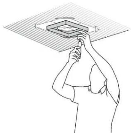
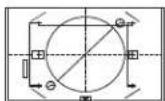
Place the template in the ceiling considering the instructions for ceiling support structures.
NOTE: Always consider the front of hood legend when playing the template on the ceiling. It will define the control's location.
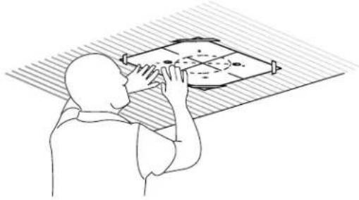
natural_image
Line drawing of a person using a handheld device to interact with a grid-based object (no text or symbols)2 Mark with a pencil the hole locations for screws and duct in the ceiling.
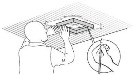
natural_image
Illustration of a person using a tool to examine a small object on a table, with no visible text or symbols.3 Fix the upper horizontal support with 4 - 5 x 45 mm screws.
natural_image
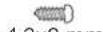
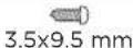
Line drawing of a person adjusting a square component under a ceiling light (no text or symbols)4 Install the 6" (15.2 cm) round transition with 2 - 3.5 x 9.5 mm screws.
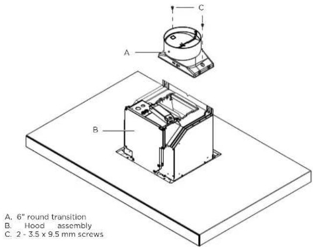
text_image
A. 6" round transition B. Hood assembly C. 2 - 3.5 x 9.5 mm screws5 Install the lower horizontal support with 8 - 4.2 x 8 mm screws.
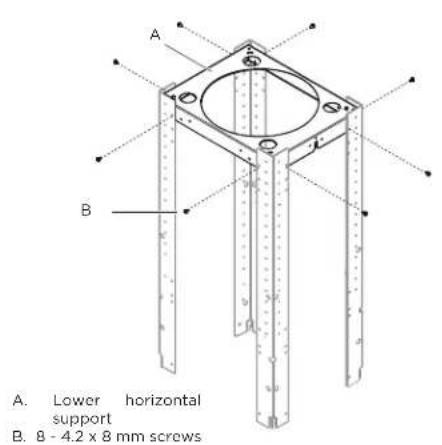
text_image
A. Lower horizontal support B. 8 - 4.2 x 8 mm screws6 Install the 4 vertical supports with 16 - 4.2 x 8 mm screws.
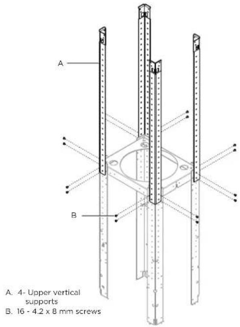
text_image
A. 4- Upper vertical supports B. 16 - 4.2 x 8 mm screws7 Install the structure to the horizontal support with 16 - 4.2 x 8 mm screws.
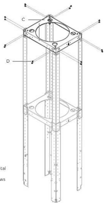
text_image
C D tal ws8 Using 2 or more people, lift the range hood assembly under the structure.
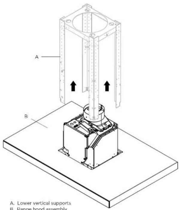
text_image
A. Lower vertical supports B. Range hood assemblyC. Upper horizontal support D. 16 - 4.2x8 mm screws
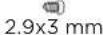
9 Attach the range hood assembly to the lower vertical supports with 2 leveling screws.
10 Install the 4 vertical supports with 16 - 4.2x8 mm screws. Check everything is tightly screwed.
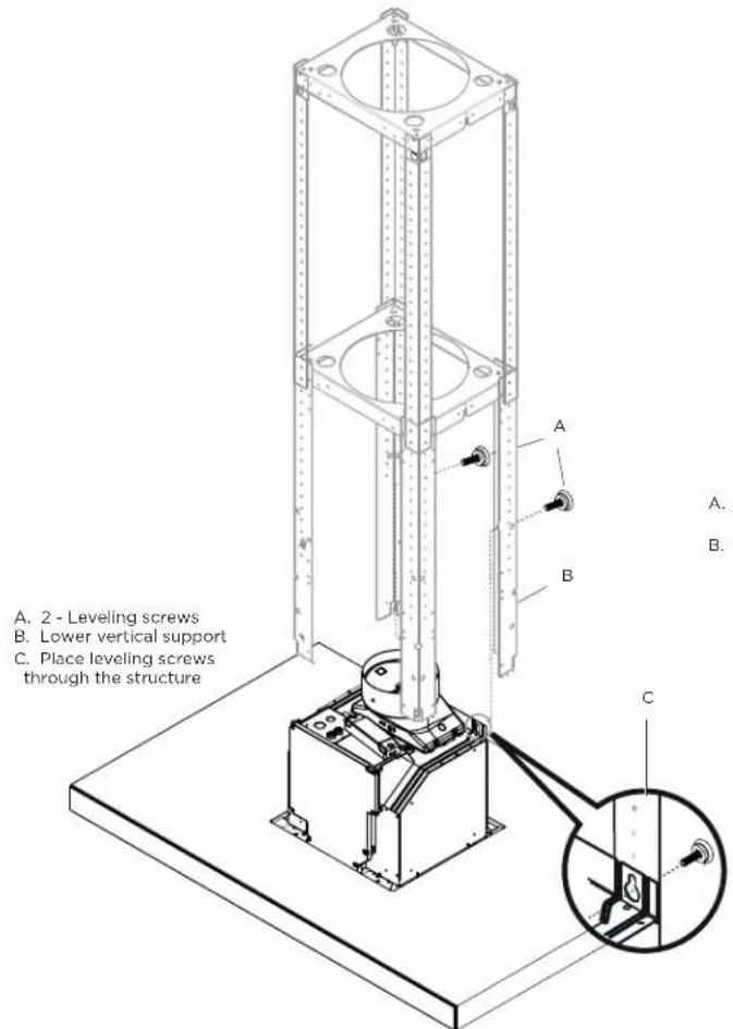
text_image
A. 2 - Leveling screws B. Lower vertical support C. Place leveling screws through the structure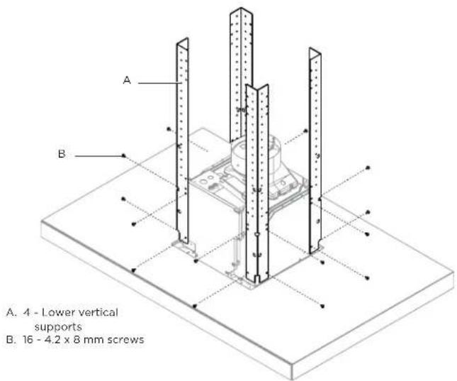
text_image
A. 4 - Lower vertical supports B. 16 - 4.2 x 8 mm screws11 Remove the 2 leveling screws from the structure.
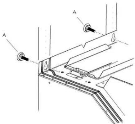
text_image
Technical diagram showing labeled components A and B with arrows indicating assembly or connection pointsA. 2 - Leveling screws
Electrical connection
I WARNING
TO REDUCE THE RISK OF FIRE, USE ONLY METAL DUCT WORK.
ELECTRICAL SHOCK HAZARD.
WARNING
TURN OFF POWER CIRCUIT AT THE SERVICE PANEL BEFORE WIRING THIS UNIT.
120 VAC, 15 OR 20 AMP CIRCUIT REQUIRED.
- Facing the front of the range hood, remove the left knockout and the Junction box cover and install the conduit connector (cULus listed) in junction box.
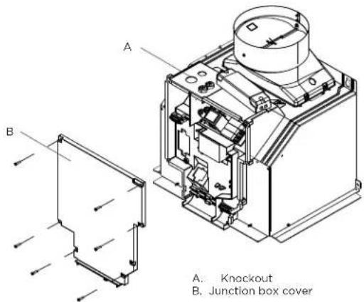
text_image
A. B. A. Knockout B. Junction box coverELECTRICAL GROUNDING INSTRUCTIONS
This appliance is fitted with an electrical junction box with 3 wires, one of which (green/yellow) serves to ground the appliance.
To protect you against electric shock, the green and yellow wire must be connected to the grounding wire in your home electrical system, and it must under no circumstances be cut or removed.
Failure to do so can result in death or electrical shock.
- If not already done, install a 12 " conduit connector in junction box.
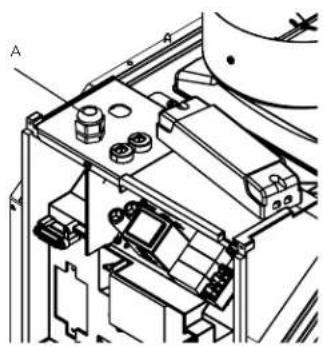
natural_image
Technical line drawing of a mechanical assembly with no visible text or symbolsA. 12 " Conduit connector
- Run home power supply cable through the conduit, into terminal box.
- Use UL listed wire connectors and connect black wires (B) together.
- Use UL listed wire connectors and connect white wires (D) together.
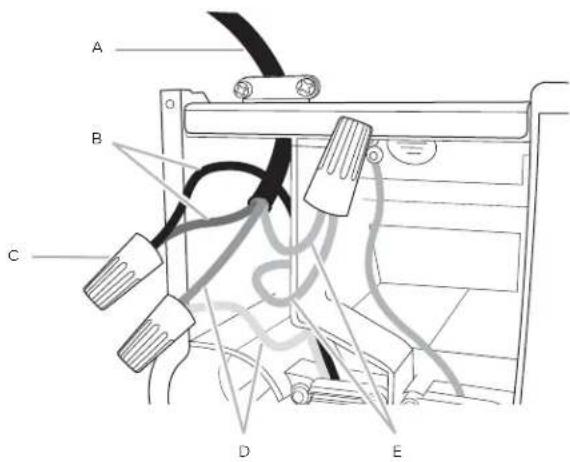
text_image
A B C D EA. Home power supply cable
B. Black wires
C. UL listed wire connectors
D. White wires
E. Green (or bare) and yellow-green ground wires
- Connect green (or bare) ground wire from home power supply to yellow-green ground wire (E) in terminal box using UL listed wire connectors.
• Tighten strain relief screw.
• Install terminal box cover. - Check that all light bulbs are secure in their sockets.
- Reconnect power
Complete the installation
ONLY FOR RECIRCULATING VERSION
(Using Recirculating Kit model KIT02665)
Air deflector installation
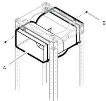
- Assemble the air deflector with the upper horizontal support with 2 assembly screws.
natural_image
Technical line drawing of a mechanical assembly with labeled components A and B (no text or symbols beyond labels)A. Air deflector B. Assembly screws
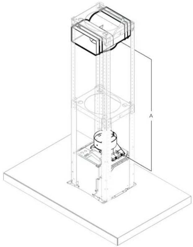
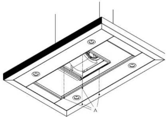
• Measure from the bottom of the air deflector to the bottom of the hood outlet, as shown.
natural_image
Isometric technical drawing of a mechanical assembly with a vertical frame and base platform (no text or symbols)A. Dimension to measure
• Cut the duct at the measured size.
- Slip the duct onto the bottom of the deflector.
- Place the duct over the exhaust outlet from the hood.
- Use duct tape to seal the deflector and at the exhaust outlet from the hood.
- Place charcoal filters. See "Maintenance" section.
Duct cover installation (both ducted and non ducted versions)
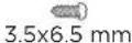
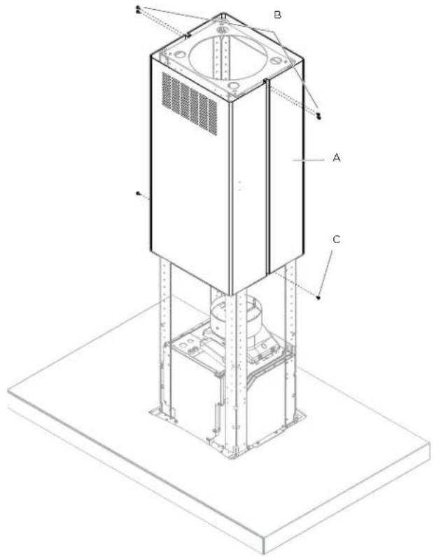
- Attach the upper duct covers using 6 - 3.5x6.5 mm screws. NOTE: For non-ducted (recirculating) installation, the slotted holes in the upper duct covers will be visible when assembled. For ducted installations, the slotted holes will be hidden down inside the lower duct covers.
text_image
Technical diagram of a mechanical device with labeled components A, B, and CA. Upper duct covers
B. 4 - 3.5x6.5 mm installation screws
C. 2 - 2.9x3 mm screws
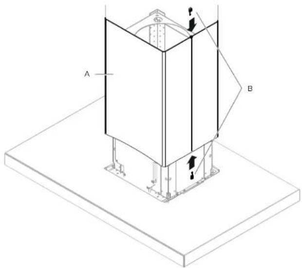
- Place lower duct covers using one plastic bracket at each side (4 needed).
text_image
A BA. Lower duct covers
B. 4 - Duct cover plastic bracket
- Secure the lower duct cover to the range hood canopy using 4 - 4.2 x 8 mm screws.
natural_image
Technical line drawing of a mechanical assembly with mounting holes and internal components (no text or symbols)A. 4 - 4.2x8 mm screws
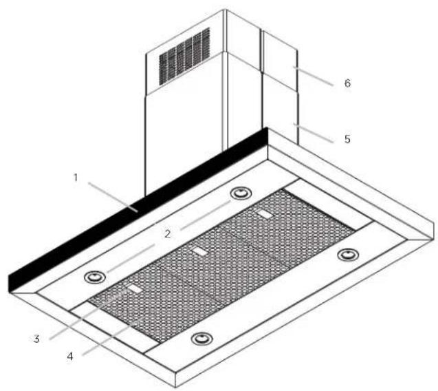
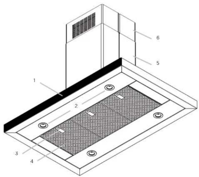
Description of the hood
text_image
Technical diagram of a roof structure with numbered components for identification- Blower and LED lamp controls
- LED lamps
- Grease filter handle
- Grease filters
- Lower duct cover
- Upper duct cover
Control

123456


- Button ON/OFF motor (stand by)
- Button for low speed (suction power) selection When flashing, it indicates that you must wash the grease filter.
- Button for medium speed (suction power) selection
- Button for high speed (suction power) selection
- Button for intensive speed (suction power) selection It lasts 5 minutes then it returns to medium speed (suction power).
- Button ON/OFF lighting Press briefly to switch on or off the lighting of the hood. Press and hold to adjust the intensity of the light.
Indicators of filter saturation:
At regular time intervals, the hood indicates the need of performing filter maintenance.
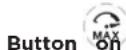
Button MAX on with steady light:
Perform grease filter maintenance.
Button flashing:
Perform activated charcoal filter maintenance.
NOTE: Filter saturation signal is visible within the first minute after switching off the hood; within this time, the reset of saturation indicators must be performed.
Reset of filter saturation indicators:
Press and hold the button

Activation of saturation indicator activated charcoal filter:
NOTE: This operation must be performed with the hood off. This indicator is normally deactivated; press and hold the
button to activate the function: the button lights up with steady light.
To deactivate the function, press and hold the button, the button lights up flashing.

CFM Reduction System
Before operating your hood:
Some States and Provinces of the US & Canada restrict the maximum exhausting airflow of range hoods. Airflow is measured as cubic feet per minute (CFM). These maximum levels allowed are detailed in the local code of your area. Please check local codes to find out if you need to restrict the maximum airflow of your hood. If your local code mandates a maximum airflow level below the maximum airflow of this hood (i.e. 600 CFM), please execute the procedure below to reduce the maximum airflow.


1 Turn the motor OFF.
2 Press the ON/OFF (1) and Intensive speed (5) buttons together for 3 seconds.
You will hear a beep and all control lights will illuminate for 3 seconds.
This action will Disable speeds 3 and 4 and effectively lower the Maximum airflow to <300 CFM.
3 Locate the CFM certification sticker in the hardware pack.
4 Peel and Affix this sticker to a visible area in the blower. This sticker provides official certification to your local inspector that this hoods maximum airflow has been reduced to <300 CFM.
Maintenance
| ATTENTION!
Before performing any maintenance operation, isolate the hood from the electrical supply by switching off at the connector and removing the connector fuse.
Or if the appliance has been connected through a plug and socket, then the plug must be removed from the socket.
Cleaning
Do not spray cleaners directly to the control while cleaning the Hood. The cooker hood should be cleaned regularly (at least with the same frequency with which you carry out maintenance of the fat filters) internally and externally. Clean using the cloth dampened with neutral liquid detergent. Do not use abrasive products. Do not use chlorine base cleaners.
DO NOT USE ALCOHOL!
Exterior surfaces:
To avoid damage to the exterior surface, do not use steel wool or soap-filled scouring pads. Do not use chlorine base cleaners. Rub in direction of the grain line to avoid scratching the surface.
WARNING
Failure to carry out the basic cleaning recommendations of the cooker hood and replacement of the filters may cause fire risks.
Therefore, we recommend oserving these instructions. The manufacturer declines all responsibility for any damage to the motor or any fire damage linked to inappropriate maintenance or failure to observe the above safety recommendations.
Grease Filter
Traps cooking grease particles.
This must be cleaned once a month using non aggressive detergents, either by hand or in the dishwasher, which must be set to a low temperature and a short cycle.
When washed in a dishwasher, the grease filter may discolour slightly, but this does not affect its filtering capacity.
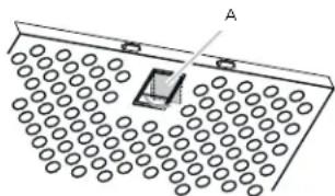
To remove the grease filter, pull the spring release handle.
natural_image
Pure diagram of a grid-like structure with circular elements and a central rectangular element, no text or symbols present.A. Spring release handle
Replacing a LED Lamp
The LED lights are replaceable by a service technician only. See "Who to contact" section in the warranty for service contact information.
Charcoal filter
| WARNING
When used in recirculation mode, To Reduce the Risk of Fire and Shock use only conversion kit Models:
Recirculating kit: KITO2665
Charcoal filter replacement: KIT02667
If the model is not vented to the outside, the air will be recirculated through disposable charcoal filters that help remove smoke and odors.
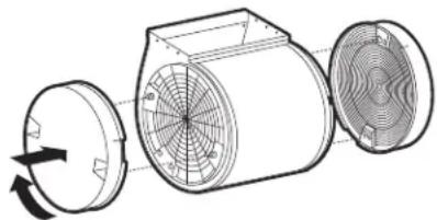
1 Cover the grill that protects the suction motor with the carbon filter so that the slots on the filter correspond to the pins on the sides of the motor protection grill.
2 Turn the carbon filter clockwise to block them (bayonet fixing).
NOTE: The charcoal filters cannot be cleaned. It should be replaced every 4-6 months (depending on hood usage).
NOTE: DO NOT rinse, or put charcoal filters in an automatic dishwasher.
NOTE: Charcoal filters are not included with the hood. They must be ordered from your supplier. Order the needed kit specifying your hood model and width size.
natural_image
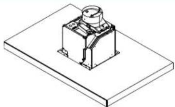
Diagram of a mechanical device showing internal components and rotation arrow (no text or symbols)TO OBTAIN SERVICE UNDER WARRANTY
Owner must present proof of original purchase date. Please keep a copy of your dated proof of purchase (sales slip) in order to obtain service under warranty.
PARTS AND SERVICE WARRANTY
For the period of two (2) years from the date of the original purchase, Elica will provide free of charge, non consumable parts or components that failed due to manufacturing defects. During these two (2) years limited warranty, Elica will also provide free of charge, all labor and in-home service to replace any defective parts.
WHAT IS NOT COVERED
• Damage or failure to the product caused by accident or act of God, such as, flood, fire or earthquake.
- Damage or failure caused by modification of the product or use of non-genuine parts.
- Damage or failure to the product caused during delivery, handling or installation.
- Damage or failure to the product caused by operator abuse.
- Damage or failure to the product caused by dwelling fuse replacement or resetting of circuit breakers.
- Damage or failure caused by use of product in a commercial application.
• Service trips to dwelling to provide use or installation guidance.
• Light bulbs, metal or carbon filters and any other consumable part.
• Normal wear of finish.
- Wear to finish due to operator abuse, improper maintenance, use of corrosive or abrasive cleaning products/pads and oven cleaner products.
WHO IS COVERED
This warranty is extended to the original purchaser for products purchased for ordinary residential use in North America (Including the United States, Guam, Puerto Rico, US Virgin Islands & Canada).
This warranty is non-transferable and applies only to the original purchaser and does not extend to subsequent owners of the product. This warranty is made expressly in lieu of all other warranties, expressed or implied, including, but not limited to any implied warranty of merchantability or fitness for a particular purpose and all other obligations on the part of Elica North America, provided, however, that if the disclaimer of implied warranties is ineffective under applicable law, the duration of any implied warranty arising by operation of law shall be limited to two (2) years from the date of original purchase at retail or such longer period as may be required by applicable law.
This warranty does not cover any special, incidental and/or consequential damages, nor loss of profits, suffered by the original purchaser, its customers and/or the users of the Products.
WHO TO CONTACT
To obtain service under warranty or for any service related question:
• Elica North America Service, call at 1 888 732 8018
• For Eastern Canada, call AGI Services at 1 888 651 2534 Ask for the service department
• elica@servicepower.com
FRANÇAIS
Table des matières
text_image
F E G H A B C D| Modèles | ||
| EMG636S1 | EMG642S1 | |
| A | 36" (91.4 cm) | 42" (106.7 cm) |
| B | 2718" (68.9 cm) | |
| C* | Min: 29^13/_16" (75.7 cm)Max: 5018" (127.3 cm) | |
| D** | Min: 29^13/_16" (75.7 cm)Max: 44^7/_8" (114 cm) | |
| E | 6" (15.9 cm) | |
| F | 12" (30.4 cm) | |
| G | 13" (33.24 cm) | |
| H | 238" (6 cm) | |
natural_image
Line drawing of a person using a handheld device to interact with a grid-based interface (no text or symbols)natural_image
Illustration of a person using a tool to examine a small object on a table, with no visible text or symbols.natural_image
Line drawing of a person using a handheld device to press or install a square component (no text or symbols present)text_image
Technical diagram showing labeled components A and B with arrows indicating assembly or connection pointsnatural_image
Technical line drawing of a mechanical assembly with no visible text or symbolsA. Serre-câble dé
text_image
Technical diagram of a mechanical assembly with labeled components A and B, showing structural details and alignment lines.natural_image
Isometric technical drawing of a mechanical lifting or mounting structure with labeled dimension A (no text or symbols beyond labels)text_image
Technical diagram of a mechanical device with labeled components A, B, and Cnatural_image
Isometric technical diagram of a mechanical assembly with labeled components A and B, showing structural elements and motion indicators (no text or symbols beyond labels)natural_image
Isometric technical drawing of a mechanical assembly with labeled component A (no text or symbols beyond label)A. 4 vis - 4.2x8 mm
Description de la hotte
text_image
Technical diagram of a ventilation system with numbered components for identificationBefore performing any maintenance operation, isolate the hood from the electrical supply by switching off at the connector and removing the connector fuse.
Or if the appliance has been connected through a plug and socket, then the plug must be removed from the socket.
Nettoyage
natural_image
Diagram of a rectangular container with circular patterns and a small object on top, labeled 'A' (no text or symbols present)natural_image
Diagram of a mechanical fan assembly with internal blades and a rotating knob (no text or symbols)POUR OBTENIR UN DEPANNAGE SOUS GARANTIE
text_image
F E G H A B C D| Modelos | ||
| EMG636S1 EMG642S1 | ||
| A 36" (91.4 cm) 42" (106.7 cm) | ||
| B 27 | 18" (68.9 cm) | |
| C* Min: 29 | ^13/_16" (75.7 cm)Max: 50%” (127.3 cm) | |
| D** Min: 29 | ^13/_16" (75.7 cm)Max: 44 ^7_8 ” (114 cm) | |
| E | 6" (15.9 cm) | |
| F | 12" (30.4 cm) | |
| G | 13" (33.24 cm) | |
| H | 238" (6 cm) | |
natural_image
Two technical line drawings of rectangular metal profiles with internal cutouts (no text or symbols)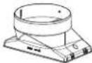


natural_image
Two ruler illustrations showing different lengths (no text or symbols)

- Phillips (Posidrive) #2
- TORX #10, #20
natural_image
Line drawing of a person using a handheld device to interact with a grid-based interface (no text or symbols)natural_image
Illustration of a person using a tool to adjust a rectangular object on a platform, with an inset showing hand positioning (no text or symbols)natural_image
Line drawing of a person using a handheld device to press or install a square component (no text or symbols present)text_image
Technical diagram showing labeled components A and a mechanical assembly with mounting holes and structural elementsnatural_image
Technical line drawing of a mechanical assembly with no visible text or symbolsnatural_image
Technical line drawing of a mechanical assembly with labeled components A and B (no text or symbols beyond labels)natural_image
Isometric technical drawing of a mechanical lifting or mounting structure with labeled components (no text or symbols present)text_image
Technical diagram of a mechanical device with labeled components A, B, and Cnatural_image
Isometric technical diagram of a mechanical assembly with labeled components A and B, showing structural elements and motion indicators (no text or symbols beyond labels)natural_image
Isometric technical drawing of a mechanical assembly with mounting holes and internal components (no text or symbols)A. 4 - Tornillos 4.2 x 8 mm
text_image
Technical diagram of a ceiling-mounted air duct with numbered components and labeled partsnatural_image
Diagram of a rectangular container with circular patterns and a small object on top, labeled 'A' (no text or symbols within the diagram itself)A. Manija de desenganche