USER MANUAL Thin P 60 X ELICA
EN Instruction on mounting and use
natural_image
Line drawing of a double-door kitchen tower with ventilation duct (no text or symbols)
natural_image
Illustration of two gloves, one with a black triangle symbol and the other with gray gloves (no text or labels)
natural_image
Pure architectural or mechanical diagram showing a stepped structure with arrows indicating direction (no text or symbols)
natural_image
Diagram of a staircase with an arched duct and directional arrows indicating flow or movement (no text or symbols)
1
natural_image
Pure mechanical diagram showing a piston-cranked press or lifting mechanism with no text, numbers, or symbols
2
3
4
5
6
natural_image
Technical line drawing of a mechanical assembly with a hand holding a tool, no visible text or symbols
natural_image
Isometric technical diagram of a mechanical device with internal components and directional arrows indicating motion (no text or symbols)
9
natural_image
Simple line drawing of a ceiling structure with a beam and vertical dashed line, no text or symbols present.
natural_image
Technical diagram showing a metal bracket with a dashed arrow indicating rotation or movement, no text or symbols present.
natural_image
Illustration of a hand holding a tool to cut a metal beam with a paperclip, no text or symbols present
12

natural_image
Illustration of hands assembling a rectangular electronic component with two U-shaped clips and a magnified view showing internal components (no text or symbols)
natural_image
Diagram showing a hand inserting a component into a device panel, with an arrow indicating the process (no text or symbols present)
natural_image
Technical line drawing of a mechanical assembly with arrows indicating motion or force direction (no text or symbols)
16
17
natural_image
Isometric technical diagram of a mechanical device with open lid and base plate, no visible text or symbols
18

natural_image
Technical line drawing of a mechanical device with an inset showing a rotating component (no text or symbols present)
19
natural_image
Technical line drawing of a mechanical component with a circular arrow symbol above it (no text or labels)
natural_image
Diagram showing a house with an upward arrow and a bracket with a dashed oval (no text or symbols)
natural_image
Technical line drawing of a mechanical device with mounting base and internal components (no text or symbols)
natural_image
Isometric technical diagram of a mechanical device with a coiled spring and housing, no visible text or symbols
natural_image
Exploded view diagram of a device housing with top, side, and internal components (no text or symbols)
natural_image
3D diagram of a mechanical component with mounting holes and internal features, showing no text or symbols.
natural_image
Technical line drawing of a mechanical component with two views (top and side), no text or symbols present.
natural_image
Technical line drawing of a mechanical assembly with internal components and mounting brackets (no text or symbols)
natural_image
Isometric line drawing of a rectangular frame with internal compartments and mounting points (no text or symbols)

natural_image
Diagram showing a device being inserted into a tray, with an inset illustrating the process (no text or symbols present)
Closely follow the instructions set out in this manual. All responsibility, for any eventual inconveniences, damages or fires caused by not complying with the instructions in this manual, is declined. This appliance is intended to be used in household and similar application such as: - staff kitchen areas in shop, offices and other working environments; - farm houses; - by clients in hotels, motels and other residential type environments; - bed and breakfast type environments.
The hood can look different to that illustrated in the drawings in this booklet. The instructions for use, maintenance and installation, however, remain the same.
- It is important to conserve this booklet for consultation at any moment. In the case of sale, cession or move, make sure it is together with the product.
- Read the instructions carefully: there is important information about installation, use and safety.
- Do not carry out electrical or mechanical variations on the product or on the discharge conduits.
- Before proceeding with the installation of the appliance verify that there are no damaged all components. Otherwise contact your dealer and do not proceed with the installation.
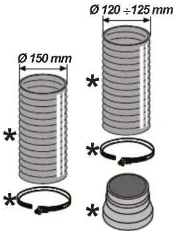
Note: The parts marked with the symbol "(*)" are optional accessories supplied only with some models or otherwise not supplied, but available for purchase.
Caution
- Before any cleaning or maintenance operation, disconnect hood from the mains by removing the plug or disconnecting the mains electrical supply.
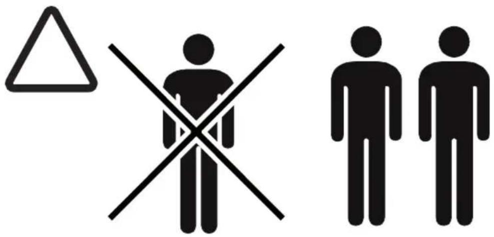
• Always wear work gloves for all installation and maintenance operations.
- This appliance can be used by children aged from 8 years and above and persons with reduced physical, sensory or mental capabilities or lack of experience and knowledge if they have been given supervision or instruction concerning use of the appliance in a safe way and understand the hazards involved.
- Children shall not be allowed to tamper with the controls or play with the appliance.
- Cleaning and user maintenance shall not be made by children without supervision.
• The premises where the appliance is
installed must be sufficiently ventilated, when the kitchen hood is used together with other gas combustion devices or other fuels.
- The hood must be regularly cleaned on both the inside and outside (AT LEAST ONCE A MONTH).
- This must be completed in accordance with the maintenance instructions provided. Failure to follow the instructions provided regarding the cleaning of the hood and filters will lead to the risk of fires.
- Do not flambé under the range hood.
- For lamp replacement use only lamp type indicated in the Maintenance/Replacing lamps section of this manual.
The use of exposed flames is detrimental to the filters and may cause a fire risk, and must therefore be avoided in all circumstances.
Any frying must be done with care in order to make sure that the oil does not overheat and ignite.
CAUTION: Accessible parts of the hood may become hot when used with cooking appliances.
- Do not connect the appliance to the mains until the installation is fully complete.
- With regards to the technical and safety measures to be adopted for fume discharging it is important to closely follow the regulations provided by the local authorities.
- The air must not be discharged into a flue that is used for exhausting fumes from appliance burning gas or other fuels.
- Do not use or leave the hood without the lamp correctly mounted due to the possible risk of electric shocks.
- Never use the hood without effectively mounted grids.
- The hood must NEVER be used as a support surface unless specifically indicated.
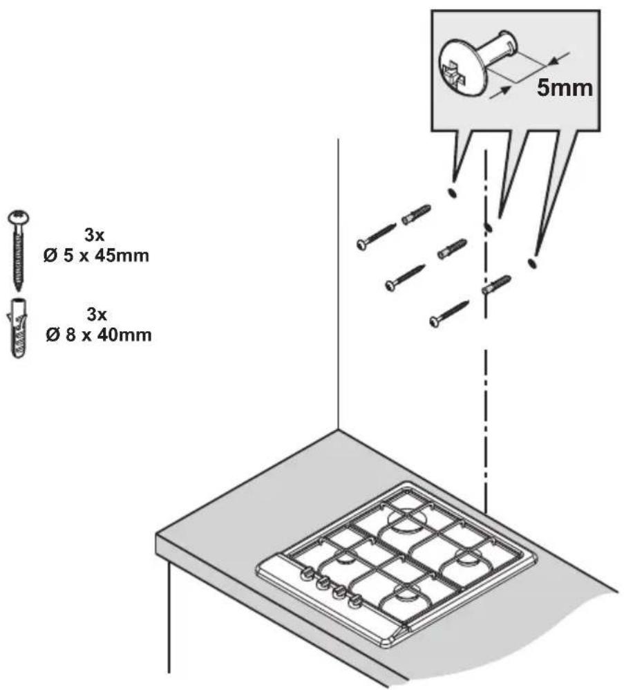
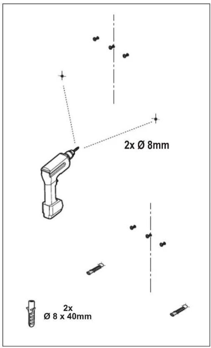
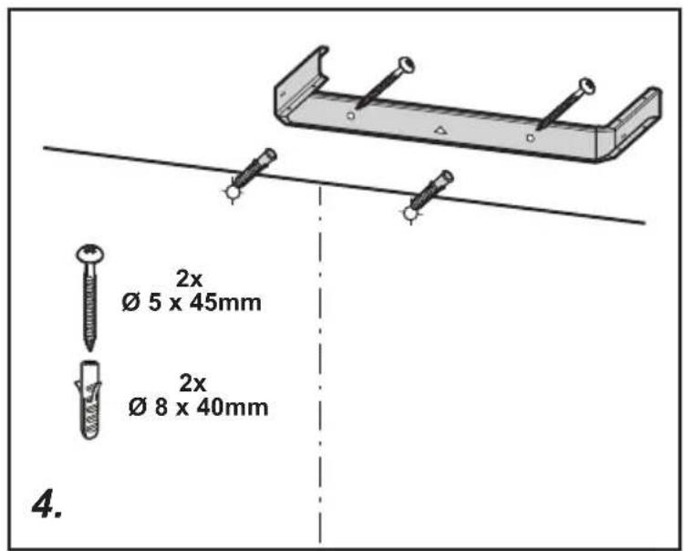
- Use only the fixing screws supplied with the product for installation or, if not supplied, purchase the correct screws type.
- Use the correct length for the screws which are identified in the Installation Guide.
- In case of doubt, consult an authorized service assistance center or similar qualified person.
WARNING!
- Failure to install the screws or fixing device in accordance with these instructions may result in electrical hazards.
- Do not use with a programmer, timer, separate remote control system or any other device that switches on automatically.
- This appliance is marked according to the European directive 2012/19/EC on Waste Electrical and Electronic Equipment (WEEE).
- By ensuring this product is disposed of correctly, you will help prevent potential negative consequences for the environment and human health, which could otherwise be caused by inappropriate waste handling of this product.

- The symbol ■ on the product, or on the documents accompanying the product, indicates that this appliance may not be treated as household waste. Instead it should be taken to the appropriate collection point for the recycling of electrical and electronic equipment. Disposal must be carried out in accordance with local environmental regulations for waste disposal.
- For further detailed information regarding the process, collection and recycling of this product, please contact the appropriate department of your local authorities or the local department for household waste or the shop where you purchased this product.
Appliance designed, tested and manufactured according to:
- Safety: EN/IEC 60335-1; EN/IEC 60335-2-31, EN/IEC 62233.
• Performance: EN/IEC 61591; ISO 5167-1; ISO 5167-3; ISO 5168; EN/IEC 60704-1; EN/IEC 60704-2-13; EN/IEC 60704-3; ISO 3741; EN 50564; IEC 62301.
- EMC: EN 55014-1; CISPR 14-1; EN 55014-2; CISPR 14-2; EN/IEC 61000-3-2; EN/IEC 61000-3-3. Suggestions for a correct use in order to reduce the environmental impact: Switch ON the hood at minimum speed when you start cooking and kept it running for few minutes after cooking is finished. Increase the speed only in case of large amount of smoke and vapor and use boost speed(s) only in extreme situations. Replace the charcoal filter(s) when necessary to maintain a good odor reduction efficiency. Clean the grease filter(s) when necessary to maintain a good grease filter efficiency. Use the maximum diameter of the ducting system indicated in this manual to optimize efficiency and minimize noise.
Any distinctive marks, differences in colour and surface deformations are not to be considered defects, but rather a characteristic of the wood, which is a noble, natural and live material that tends to alter over time. This makes each product unique and one of a kind.
Use
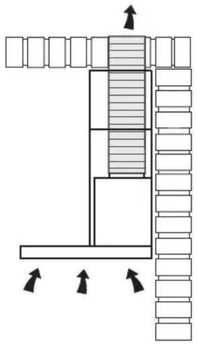
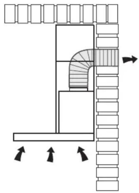
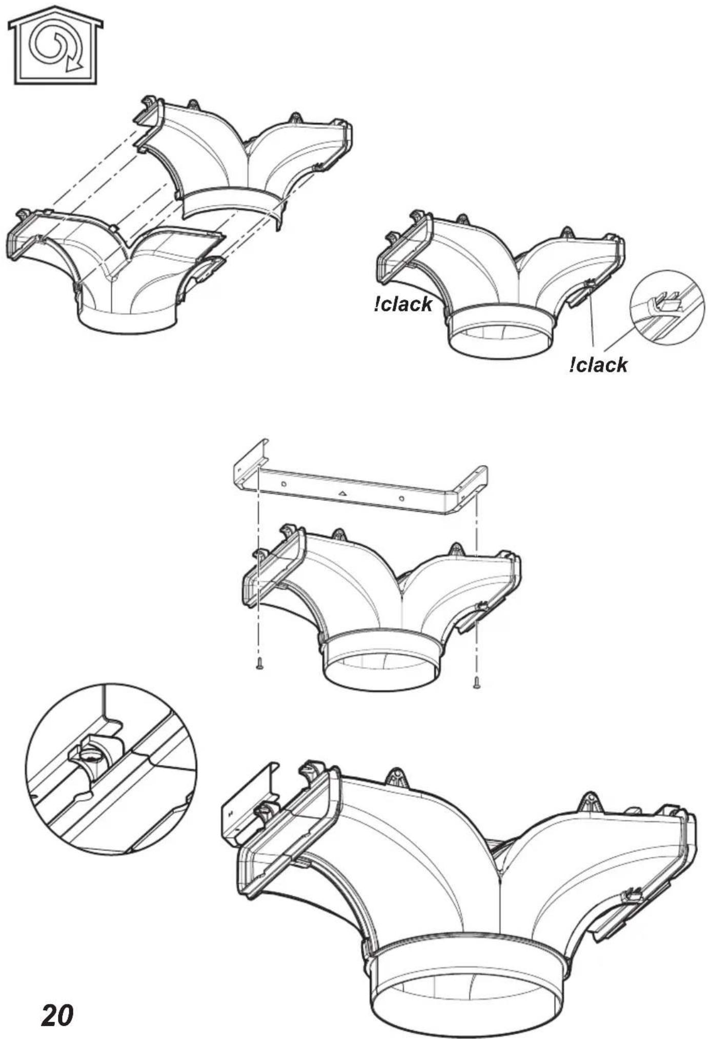
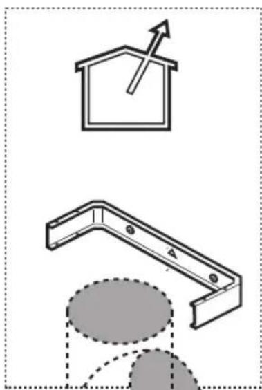
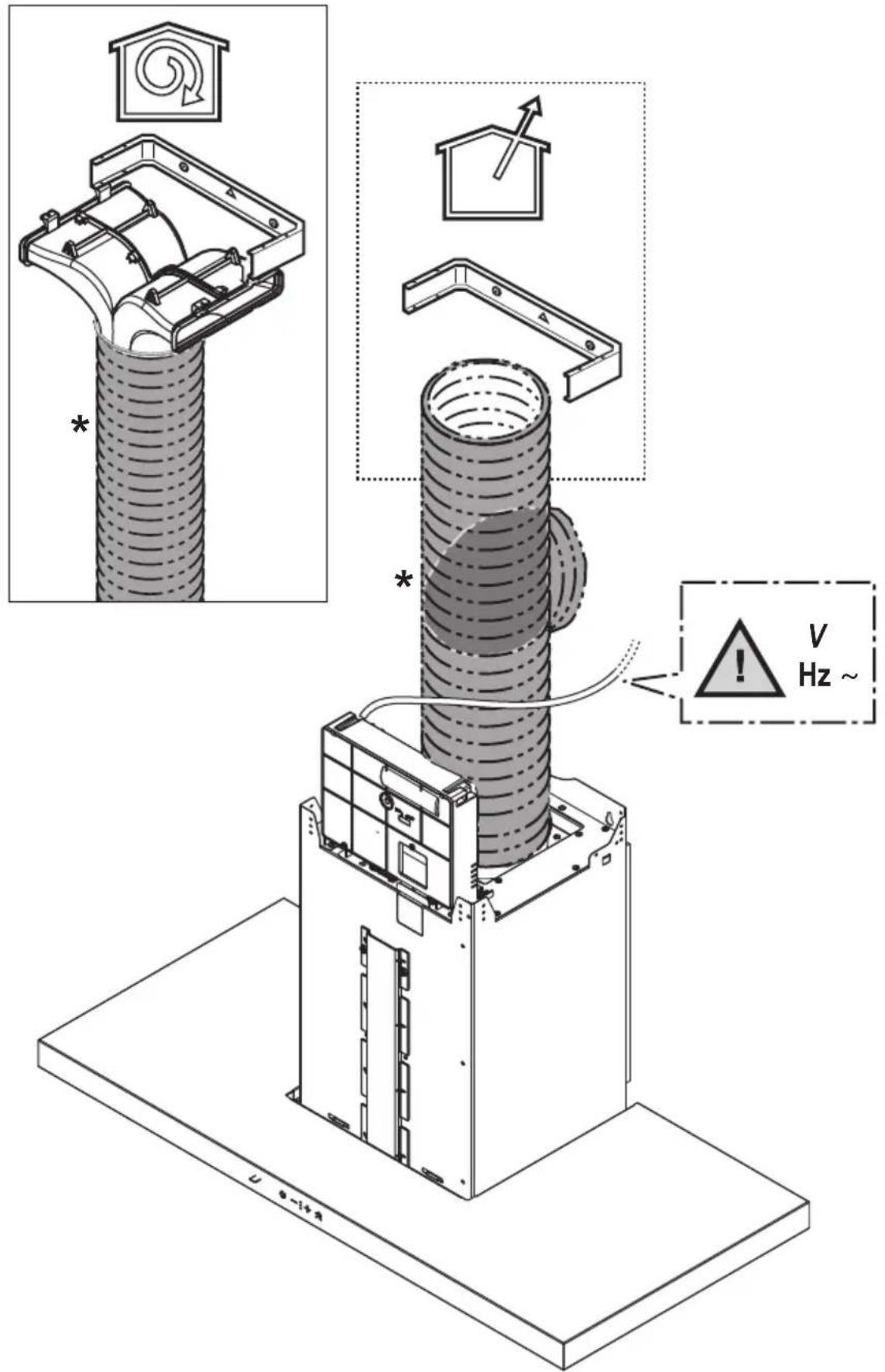
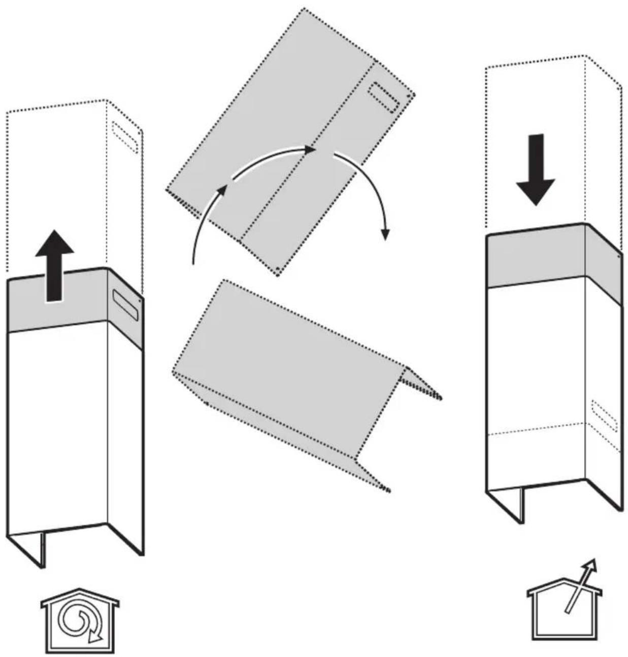
The hood is designed to be used either for exhausting or filter version.

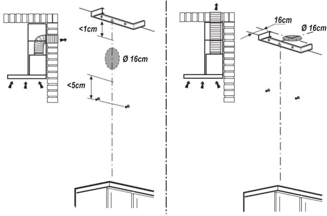
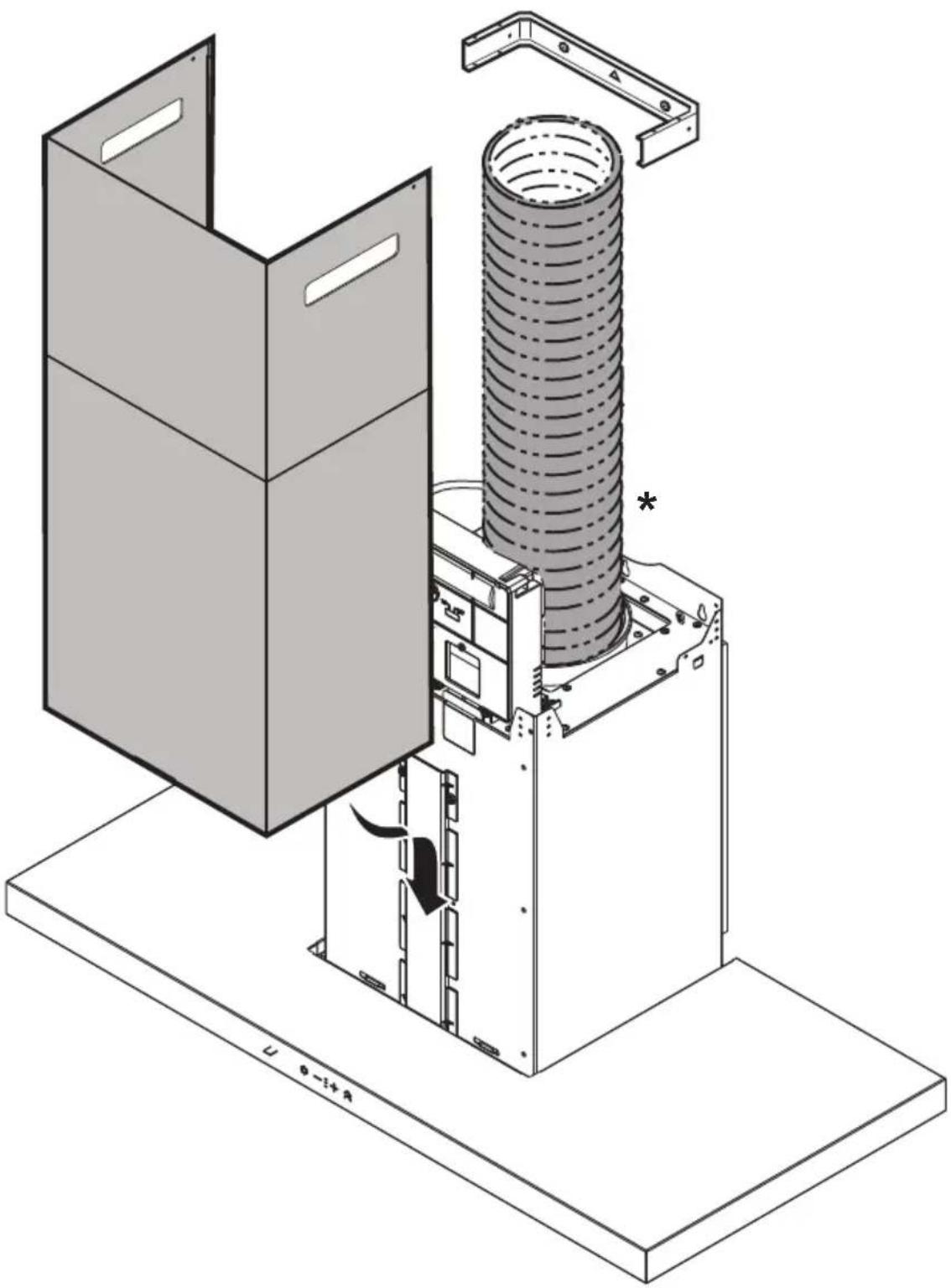
In this case the fumes are conveyed outside of the building by means of a special pipe connected with the connection ring located on top of the hood.
CAUTION!
The exhausting pipe is not supplied and must be purchased apart.
Diameter of the exhausting pipe must be equal to that of the connection ring.
CAUTION!
If the hood is supplied with active charcoal filter, then it must be removed.
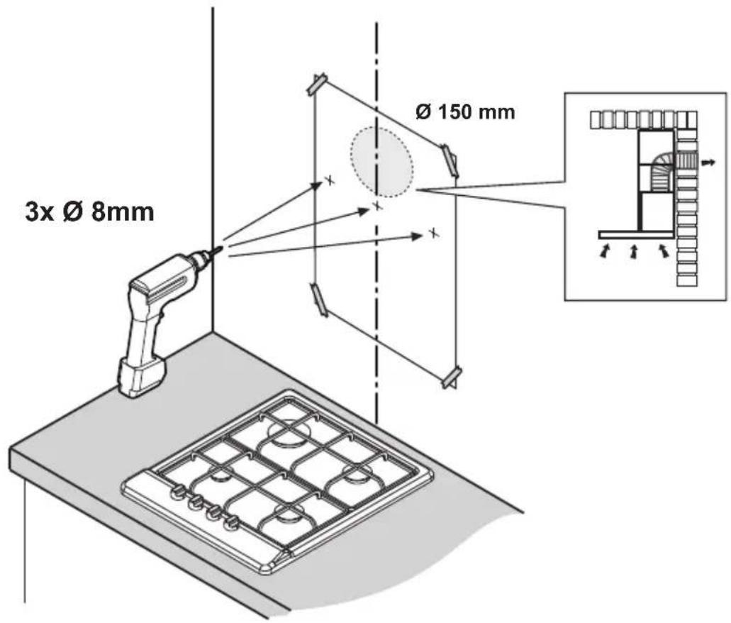
Connect the hood and discharge holes on the walls with a diameter equivalent to the air outlet (connection flange).
Using the tubes and discharge holes on walls with smaller dimensions will cause a diminution of the suction performance and a drastic increase in noise.
Any responsibility in the matter is therefore declined.
! Use a duct of the minimum indispensable length.
! Use a duct with as few elbows as possible (maximum elbow angle: 90°).
! Avoid drastic changes in the duct cross-section.

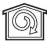
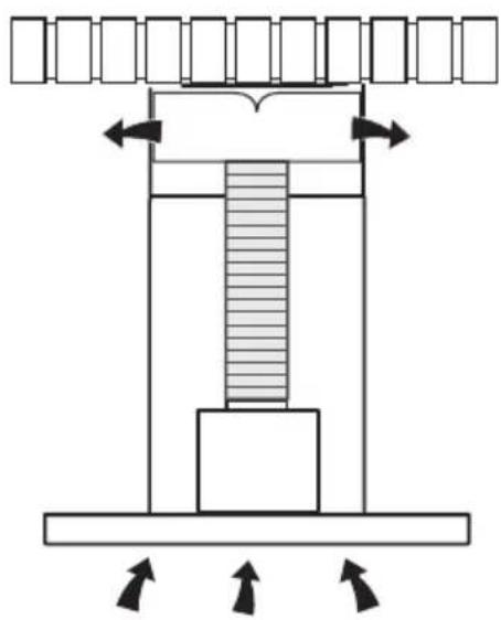
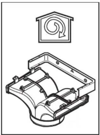
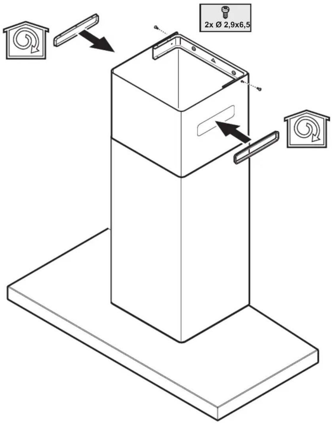
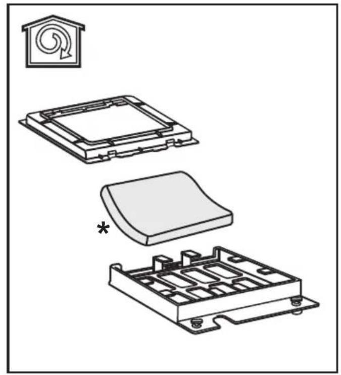
Filtration version
The aspirated air will be degreased and deodorised before being fed back into the room.
In order to use the hood in this version, you have to install a system of additional filtering based on activated charcoal.
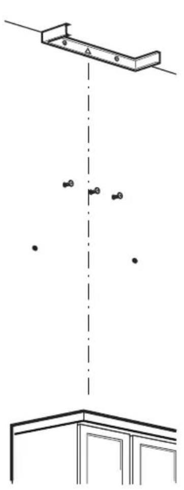
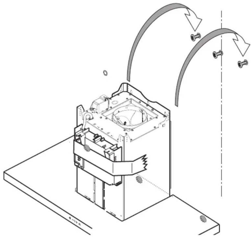
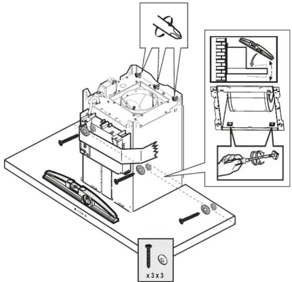
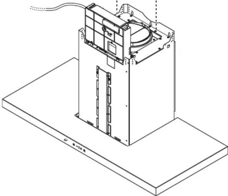
Installation
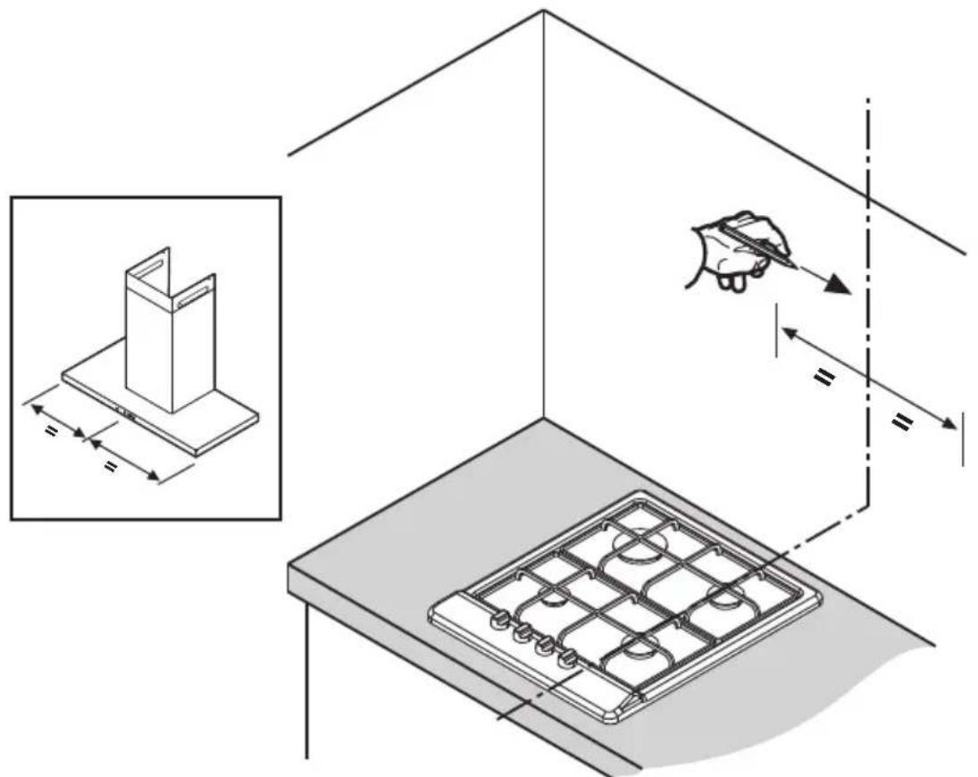
The minimum distance between the supporting surface for the cooking equipment on the hob and the lowest part of the range hood must be not less than 50cm from electric cookers and 65cm from gas or mixed cookers.
If the instructions for installation for the gas hob specify a greater distance, this must be adhered to.

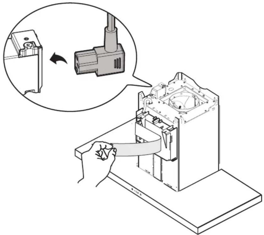
Electrical connection
The mains power supply must correspond to the rating indicated on the plate situated inside the hood. If provided with a plug connect the hood to a socket in compliance with current regulations and positioned in an accessible area, after installation. If it not fitted with a plug (direct mains connection) or if the plug is not located in an accessible area, after installation, apply a double pole switch in accordance with standards which assures the complete disconnection of the mains under conditions relating to over-current category III, in accordance with installation instructions.

WARNING!
Before re-connecting the hood circuit to the mains supply and checking the efficient function, always check that the mains cable is correctly assembled.
The hood is provided with a special power cable; if the cable is damaged, request a new one from Technical Service.
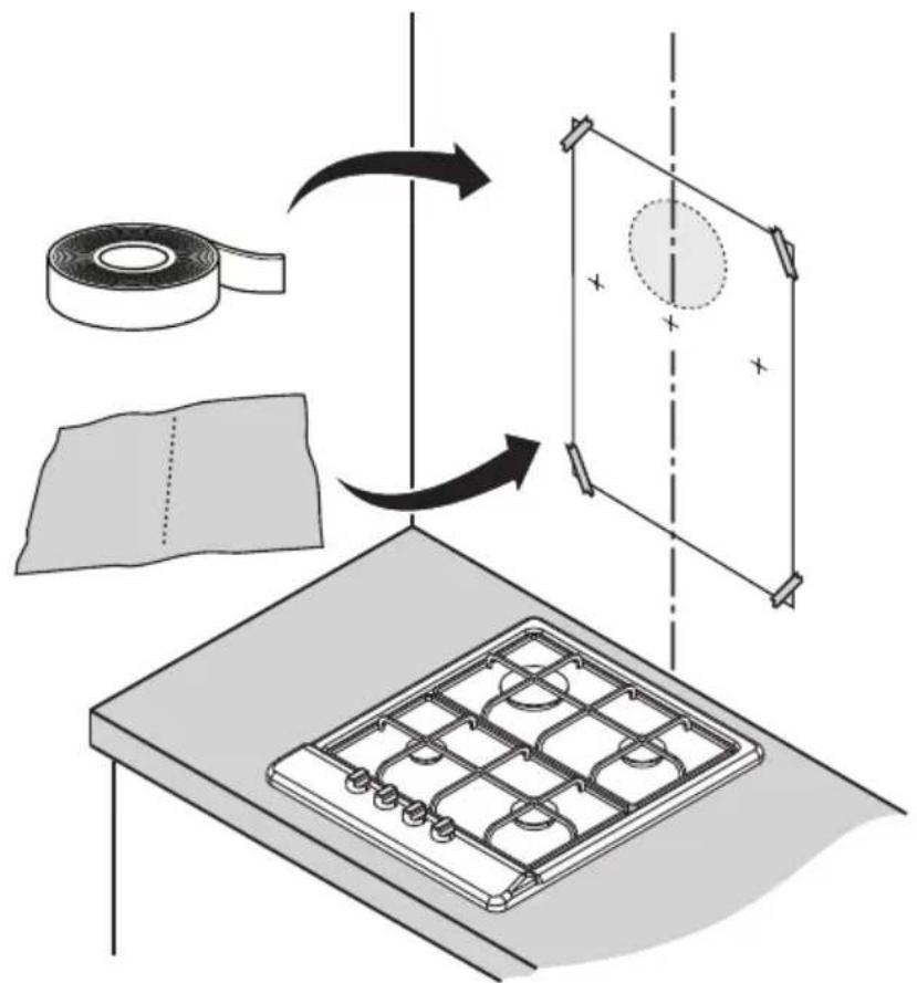
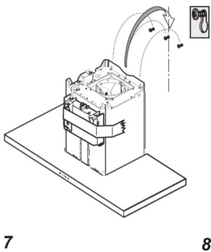
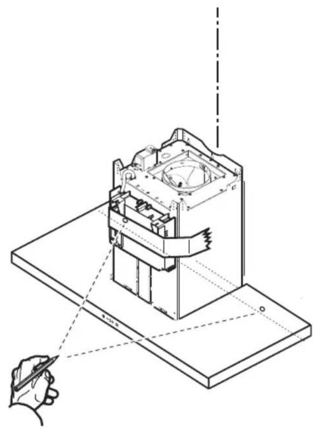
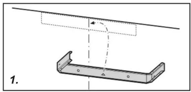
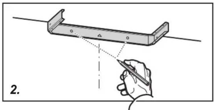
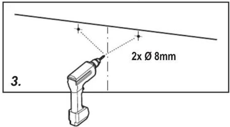
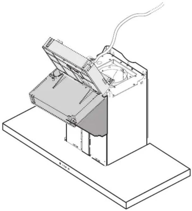
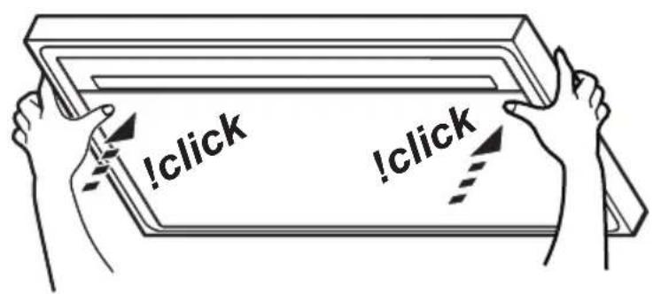
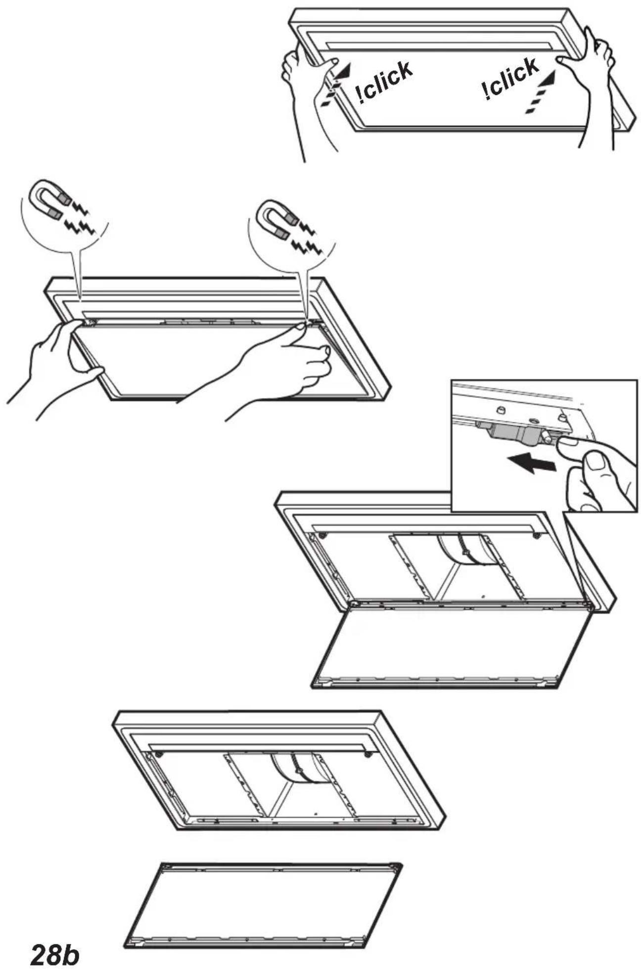
Mounting
Before beginning installation:
- Check that the product purchased is of a suitable size for the chosen installation area.
- Remove the charcoal (*) filter/s if supplied (see also relative paragraph). This/these is/are to be mounted only if you want to use the hood in the filtering version.
- Check (for transport reasons) that there is no other supplied material inside the hood (e.g. packets with screws (*), guarantees (*), etc.), eventually removing them and keeping them.
Very heavy product; hood handling and installation must be carried out by at least two persons.
Operation
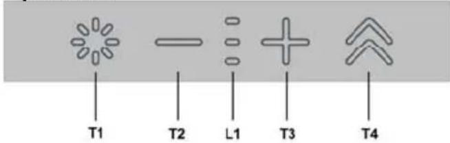
T1. Light ON/OFF button
T2. Decrease intake speed / motor off button
L1. Speed indicator LED on
T3. Motor on / increase intake speed button
T4. "BOOST" – intensive speed - function button
to turn the light on and off
press the decrease the intake power, until the extractor hood is turned off.
press and hold to turn the hood off directly.
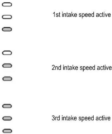
L1: Speed indicator LED on
the central LEDs light up according to the intake speed active/used
press to turn the hood on
press to increase the intake power.
T4: "BOOST" – intensive speed - function button
press T4 to activate the intensive intake speed "BOOST 1", timed for 30 minutes
this prolonged timing has been designed to guarantee a useful cooking time when a high smoke content is produced while cooking
Note : after the 30 minutes, the hood will go back to the previously set intake speed ***
with the motor on "BOOST 1", press T4 again to activate the intensive intake speed "BOOST 2", timed for 7 minutes
Note : after the 10 minutes, the hood will go back to the previously set intake speed ***
Note : press T4 again, during the 7 minutes, to go back to the previously set intake speed ***
with the "BOOST1" and "BOOST2" functions active, press:

to go back to the previously set intake speed
***

to go back to the 3rd intake speed
*** the previous intake speed remains visible via the indicator LEDs L1
- if you have set the intensive speed directly with the hood off, the motor will be turned off.
While using the "BOOST" functions, the T4 symbol flashes :

( "BOOST 1": white light - "BOOST 2": blue light)
Filter saturation indicators
At regular intervals, the hood signals the need to perform maintenance on the filters.
LED (L1) on and flashing light (all indicator lights flashing together): perform maintenance on the grease filter.
LED (L1) on and alternating light (the indicator lights turn on in sequence): perform maintenance on the active carbon filter
Note: The filter saturation indicator is visible within the first 10 seconds on turning on the hood; the saturation indicators must be reset within this time.
Reset filter saturation indicator:
Press and hold button

LED = (L1) turns on and off (depending on the type of filter being reset, the indicator lights flash together or turn on in sequence); an acoustic signal will confirm the operation.
Activation of filter saturation indicator
Note: this operation must be performed with the hood off.
- Grease filter
This indicator is normally activated
1st prolonged press of buttons
if the indicator is active, button
press button, to deactivate it
if the indicator is not active, button
press + button, to activate it
- turns on
- Active carbon filter
This indicator is normally deactivated
2nd prolonged press of buttons
if the indicator is active, button
press button, to deactivate it

if the indicator is not active, button
press + button, to activate it
— turns on
Maintenance
Cleaning
Clean using ONLY a cloth dampened with neutral liquid detergent. DO NOT CLEAN WITH TOOLS OR
INSTRUMENTS. Do not use abrasive products. DO NOT USE ALCOHOL!
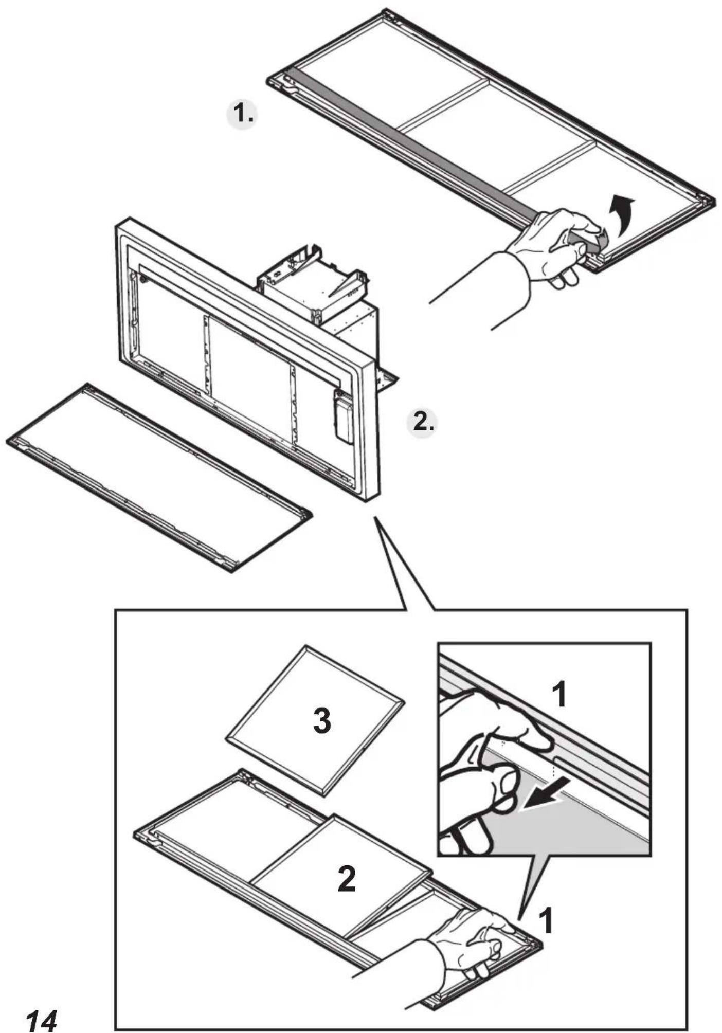
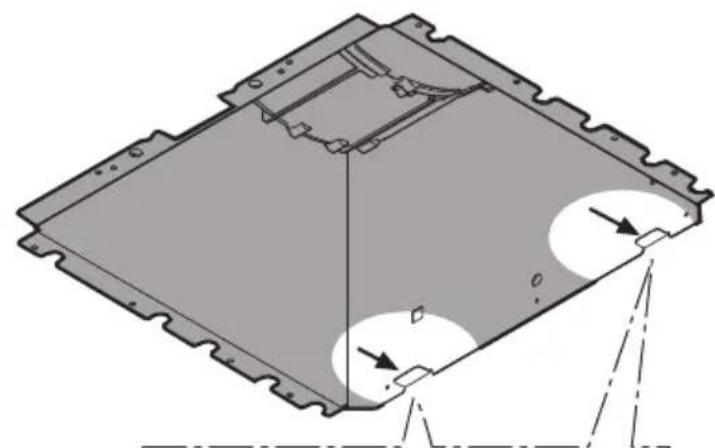
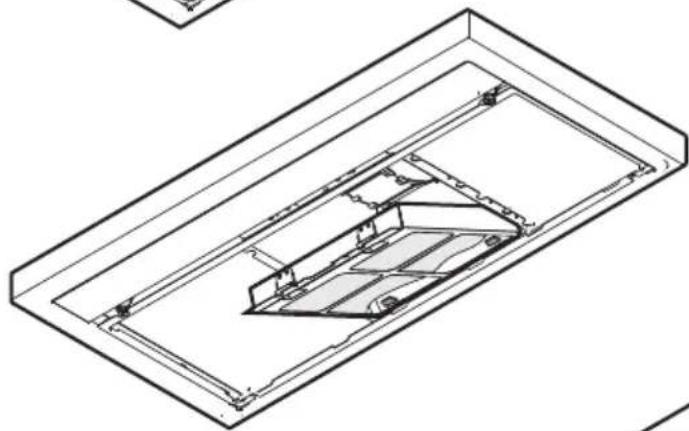
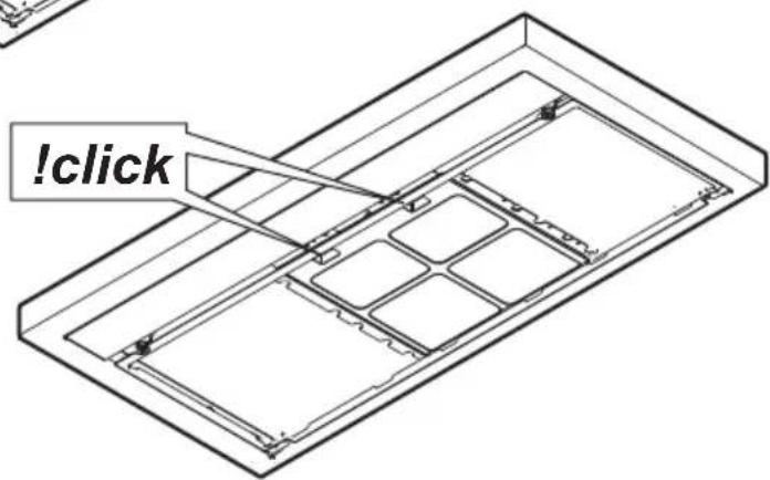
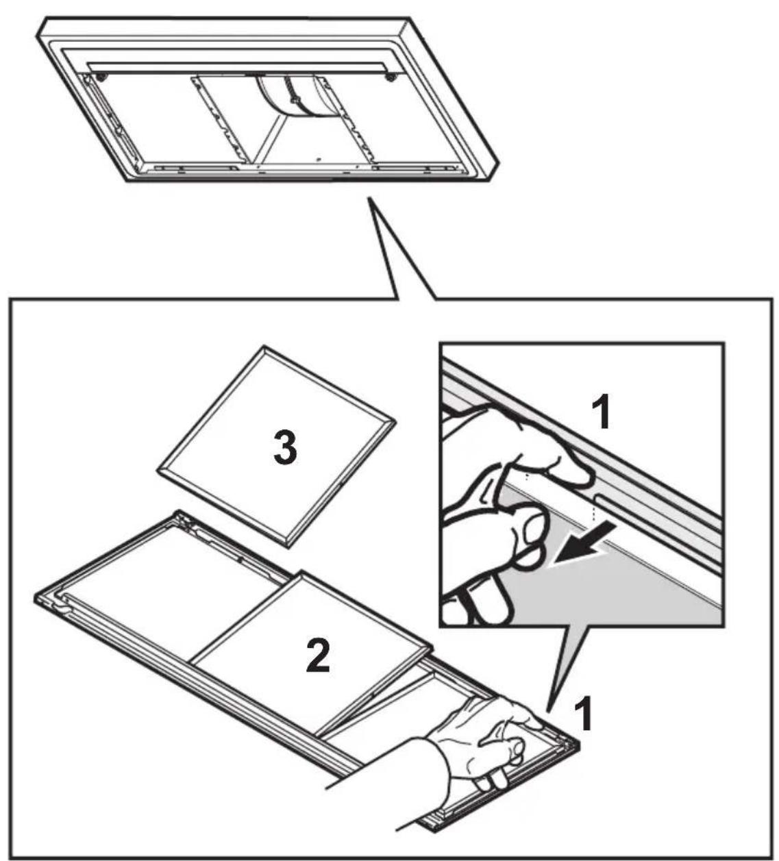
Grease filter
Fig. 14-27
Traps cooking grease particles.
This must be cleaned once a month (or when the filter saturation indication system – if envisaged on the model in possession – indicates this necessity) using non aggressive detergents, either by hand or in the dishwasher, which must be set to a low temperature and a short cycle.
When washed in a dishwasher, the grease filter may discolor slightly, but this does not affect its filtering capacity.
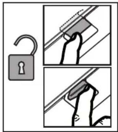
To remove the grease filter, pull the spring release handle.
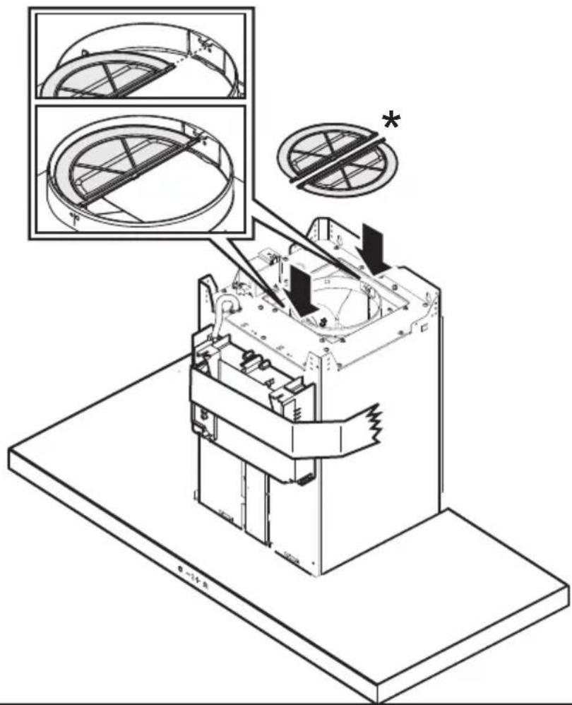
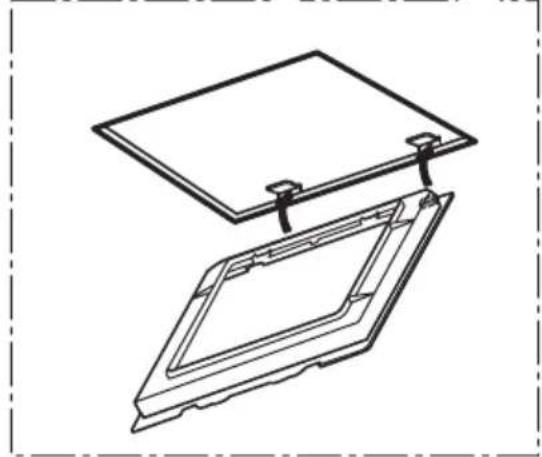
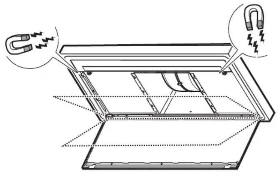
Charcoal filter (filter version only)
Fig. 26
It absorbs unpleasant odors caused by cooking.
The charcoal filter can be washed once every two months (or when the filter saturation indication system – if envisaged on the model in possession – indicates this necessity) using hot water and a suitable detergent, or in a dishwasher at 65^ C (if the dishwasher is used, select the full cycle function and leave dishes out).
Eliminate excess water without damaging the filter, then put it in the oven for 10 minutes at 100^ C to dry completely. Replace the mattress every 3 years and when the cloth is damaged.
Replacing lamps
The hood is equipped with a lighting system based on LED technology.
The LEDs guarantee an optimum lighting, a duration up to 10 times as long as the traditional lamps and allow to save 90% electrical energy.
For replacement, contact the technical service.
Activering indicator verzadiging filters