
ESub - Subwoofer JL Audio - Free user manual and instructions
Find the device manual for free ESub JL Audio in PDF.
| Product Type | Amplified subwoofer (sealed enclosure) |
| Brand | JL Audio |
| Model | ESub (e110 / e112) |
| Speaker Driver | e110: 25 cm (10 in); e112: 28 cm (12 in) - long excursion |
| Peak-to-Peak Excursion | e110: > 64 mm; e112: > 76 mm |
| Frequency Response (anechoic) | e110: 25 Hz – 116 Hz (±1.5 dB); e112: 22 Hz – 118 Hz (±1.5 dB) |
| Amplifier Power (RMS) | e110: 1,200 W; e112: 1,500 W |
| Amplifier Topology | Class D PWM switching |
| Built-in Active Crossover | Linkwitz-Riley 24 dB/octave, variable from 25 to 130 Hz, defeatable |
| Phase Adjustment | 0° to 280° (reference at 80 Hz) |
| Polarity | 0° or 180° (switch) |
| Master Level | Variable (mute to +15 dB relative to reference gain) |
| Power Modes | Off, On, Auto (signal sensing) |
| Power Supply | Regulated PWM switching (120 V, 230 V, etc. depending on version) |
| Audio Inputs | Stereo RCA line (2 x RCA); Speaker-level (removable 4-pin connector) |
| Audio Outputs | Stereo RCA line (pass-through or high-pass depending on crossover) |
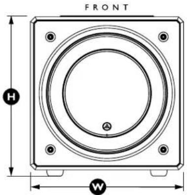
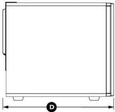
| Dimensions (H x W x D) | e110: 362 x 343 x 419 mm; e112: 412 x 394 x 467 mm |
| Net Weight | e110: 23.9 kg; e112: 33.3 kg |
| Finish | Gloss black or vinyl wrap |
| Included Accessories | Power cord (1.8 m), owner's manual |
| Warranty | Limited warranty (see manual) |
| Safety | Important safety instructions, grounding, lightning protection |
Frequently Asked Questions - ESub JL Audio
User questions about ESub JL Audio
0 question about this device. Answer the ones you know or ask your own.
Ask a new question about this device
Download the instructions for your Subwoofer in PDF format for free! Find your manual ESub - JL Audio and take your electronic device back in hand. On this page are published all the documents necessary for the use of your device. ESub by JL Audio.
USER MANUAL ESub JL Audio
E-Sub Powered Subwoofer
natural_image
Technical line drawing of a square mechanical component with concentric rings and mounting holes (no text or symbols)e112 e110
natural_image
Technical line drawing of a square speaker or antenna with concentric rings and mounting holes (no text or symbols)Owner's Manual
Manuel de l'utilisateur • Manual del propietario • Bedienungsanleitung
Manuale del proprietario • 用户手册
IMPORTANT SAFETY INSTRUCTIONS
WARNING: TO REDUCE THE RISK OF FIRE OR ELECTRIC SHOCK, DO NOT EXPOSE THIS PRODUCT TO RAIN OR MOISTURE.
CAUTION
RISK OF ELECTRIC SHOCK DO NOT OPEN

CAUTION: TO REDUCE THE RISK OF ELECTRIC SHOCK, DO NOT REMOVE COVER. NO USER SERVICEABLE PARTS INSIDE. REFER SERVICING TO QUALIFIED PERSONNEL.
- Read the Instructions — All safety and operating instructions should be read before the subwoofer is operated.
- Retain the Instructions — The safety and operating instructions should be retained for future reference.
- Heed Warnings — All warnings on the subwoofer and in the operating instructions should be followed.
- Follow Instructions — All operating and use instructions should be followed.
- Water and Moisture — The subwoofer should NOT be used near water – for example, near a bathtub, washbowl, sink, laundry tub, in a wet basement, near a swimming pool, etc.
- Ventilation — The subwoofer should be situated so that its location or position does not interfere with its proper ventilation. For example, the subwoofer should not be situated on a bed, sofa, rug, or similar surface that may block airflow over the heatsink fins. If placing the subwoofer in a “built-in” installation, ensure that airflow to the heat sink at the rear of the subwoofer is not impeded. Do not cover the subwoofer heatsink with tablecloths, curtains, etc.
- Heat and Flames — The subwoofer should be situated away from heat sources such as radiators, heat registers, stoves, fireplaces, or other devices which produce heat. Do not place candles on top of or near the subwoofer.
- Power sources — The subwoofer should only be connected to a power supply of the type described in the operating instructions or as marked on the subwoofer.
- Power Cord Protection — Power-supply cords should be routed so that they are not likely to be walked on or pinched by items placed upon or against them, paying particular attention to cords at plugs, convenience receptacles, and the point where they exit the subwoofer.
- Cleaning — The subwoofer should be cleaned only as recommended in the operating instructions.
- Nonuse Periods — The power cord of the subwoofer should be unplugged from the outlet when the subwoofer is left unused for long periods of time.
- Lightning and Power Surges — We recommend that you disconnect the subwoofer from the electrical outlet during electrical storms and/or recurring power interruptions to prevent damage due to power surges.
The lightning flash with arrowhead symbol, within an equilateral triangle, is intended to alert the user to the presence of uninsulated “dangerous voltage” within the product’s enclosure that may be of sufficient magnitude to constitute a risk of electric shock to persons.

The exclamation point within an equilateral triangle is intended to alert the user to the presence of important operating and maintenance instructions in the literature accompanying the product.
-
Object or Liquid Entry — Care should be taken so that objects do not fall into and liquids are not spilled onto the subwoofer enclosure. Do not expose the subwoofer to dripping or splashing from liquids. Do not place objects filled with liquids on top of, or near the subwoofer. For example: flower vases, beverages, liquid-fueled lamps, etc.
-
Damage Requiring Service — The subwoofer should be serviced by qualified service personnel when:
a. the power-supply cord or plug has been damaged
b. objects have fallen or liquid has been spilled into the subwoofer
c. the subwoofer has been exposed to rain
d. the subwoofer does not appear to operate normally or exhibits a marked change in performance
e. the subwoofer has been dropped or the cabinet has been damaged
f. the subwoofer driver's cone and/or suspension has been physically damaged
- Servicing — The user should not attempt to service the subwoofer beyond what is described in the operating instructions. All other servicing should be referred to qualified service personnel.
- Overloading — Do not overload wall outlets, extension cords, or outlet strips as this can result in a risk of fire or electric shock.
- Grounding — This subwoofer is supplied with a three-prong, grounded power cord. Precautions should be taken so that the grounding means of the subwoofer are not defeated. Defeating the grounding prong on the subwoofer power cord could increase the risk of electric shock and could result in permanent damage to the subwoofer's electronics.
THIS SUBWOOFER IS CAPABLE OF PRODUCING VERY HIGH SOUND PRESSURE LEVELS. PLEASE EXERCISE RESTRAINT IN ITS OPERATION TO PROTECT YOUR HEARING FROM PERMANENT DAMAGE.
WARNING

FCC COMPLIANCE STATEMENT
NOTE: This equipment has been tested and found to comply with the limits of Part 15 of the FCC Rules. These limits are designed to provide reasonable protection against harmful interference in a residential installation. This equipment generates, uses and can radiate radio frequency energy and, if not installed in accordance with the instructions, may cause harmful interference to radio communications. However, there is no guarantee that interference will not occur in a particular installation. If this equipment does cause harmful interference to radio or television reception, which can be determined by turning the equipment off and on, the user is encouraged to try to correct the interference by one or more of the following measures:
- Reorient or relocate the receiving antenna.
- Increase the separation between the equipment and receiver.
- Connect the equipment into an outlet on a circuit different from that to which the receiver is connected.
- Consult the dealer or an experienced radio/TV technician for help.
TABLE OF CONTENTS
Important Safety Instructions: 2-3
Introduction: 4
Product Overview: 5
Placing your E-Sub in Your Listening Room: 6-10
Unpacking your E -Sub: 11
Top-Mounted Control Panel Layout: 12
Rear Connection Panel Layout:.... 13
Top-Mounted Controls in Detail:....14-16
Connecting your E -Sub(s): 17-23
Recommended Setup Procedure: 24-26
Frequently Asked Questions: 27
Cleaning Your E-Sub: 28
Troubleshooting: 29
Limited Warranty / Service Information: 31
Specifications: 32
INTRODUCTION
Congratulations on your purchase of a JL Audio E-Sub powered subwoofer system. This product has been critically engineered to deliver exceptional performance in your home theater or audio system for many years to come.
As a company, we are intensely committed to core research into high-performance loudspeaker and amplifier technologies. JL Audio's long-excursion subwoofer driver designs are widely considered as reference standards for linear behavior and high output. We have also focused our efforts to create powerful amplifier and signal-processing technologies specifically aimed at delivering exceptional low-frequency performance. Your E-Sub combines these core disciplines within a compact, beautifully crafted package to deliver an unparalleled listening experience.
We sincerely thank you for your purchase and invite you to read this manual thoroughly in order to achieve the highest level of performance with your E-Sub subwoofer system. Enjoy.
JL AUDIO TECHNOLOGIES INCLUDED IN E-Sub SUBWOOFERS
DMA-Optimized Motor System
DMA is JL Audio's innovative Dynamic Motor Analysis system aimed at improving dynamic motor behavior. As a result of DMA optimization, loudspeaker motors remain linear in force over an extreme range of excursion and also maintain a highly stable fixed magnetic field over a wide power range. This leads to vastly reduced distortion and faithfully reproduced transients... or put simply: tight, clean, articulate bass.
VRC-Vented Reinforcement Collar
JL Audio's Vented Reinforcement Collar improves the rigidity and stability of the cone/spider/voice coil junction and directs airflow over the voice coil windings for improved thermal performance.
Floating-Cone™ Attach Method
This assembly technique ensures proper surround geometry in the assembled speaker for better excursion control and dynamic voice coil alignment.
Engineered Lead-Wire System (U.S. Patent #7,356,157)
Carefully engineered lead-wire design and attachments ensure controlled, quiet lead-wire behavior under the most extreme excursion demands, resulting in reduced distortion, reduced mechanical noise and improved reliability.
PRODUCT OVERVIEW
JL Audio E-Sub subwoofers combine a state-of-the-art JL Audio subwoofer driver and electronics/amplifier package within a highly optimized enclosure to deliver an exceptional listening experience in your home theater or home audio system.
The subwoofer driver in your E-Sub subwoofer system is capable of outstanding linear excursion without distress or audible distortion. This purpose-engineered driver enables your E-Sub to reproduce powerful low-frequency events with stunning impact and outstanding accuracy. The E-Sub drivers offer peak-to-peak excursion capabilities well in excess of 2.5 inches (64 mm - e110), and 3 inches (76 mm - e112) to comfortably handle the dynamics of the most demanding program material.
To get the most from this long excursion driver platform, your E-Sub incorporates a precisely engineered switching amplifier. The E-Sub amplifiers are capable of unclipped output voltages equivalent to 1200 watts (e110), and 1500 watts (e112) of RMS power when referenced to the nominal loudspeaker impedance, allowing us to take full advantage of each driver's full excursion envelope.
The beautiful cabinet enclosing the workings of your E-Sub is also the result of careful engineering. To contain the pressures created by the E-Sub driver, we utilize solid, CNC-cut, MDF material with extensive internal bracing features and advanced assembly techniques.
The E-Subs also include an on-board 2-way active crossover, permitting them to support a conventional 2-channel audio system by providing a high-pass filtered output to the main speakers' amplifier, while delivering a low-pass filtered signal to the internal subwoofer amplifier. A polarity switch and phase control are provided to aid in achieving an optimal acoustic transition between the subwoofer(s) and main speakers. Inputs are via a pair of line level stereo RCA inputs or via a removable plug for speaker level inputs.
As you can see from this brief introduction, there is a lot of technology in this compact subwoofer. The contents of this manual will explain the features, and guide you through the setup and tuning of your E-Sub to help achieve an outstanding low-frequency listening experience.
If you require assistance, we urge you to contact your authorized JL Audio retailer for expert setup advice and service.
IMPORTANT

IMPORTANT! IT IS A VERY GOOD IDEA TO READ THE NEXT SECTION BEFORE UNPACKING YOUR E-SUB. UNPACKING THE SUBWOOFER NEAR ITS FINAL LOCATION IS RECOMMENDED.
PLACING YOUR E-SUB IN YOUR LISTENING ROOM:
Your listening room or theater is an integral part of your sound reproduction system. The physical dimensions of the room and its furnishings, materials, doors and windows play an important role in defining how your system sounds.
When you place a sound source in an enclosed rectangular space, “standing waves” are created, resulting from the relationship between the sound’s wavelength and your room’s dimensions. In other words, standing waves result from sound energy that is trapped in the room as it bounces back and forth between opposing walls. Standing waves in the room create acoustic peaks and dips where the sound is either louder or softer, based solely on your physical position in the room. Energy also “builds up” at the room’s boundaries, creating exaggerated bass response at certain frequencies. These fundamental room resonances are called room “modes.”
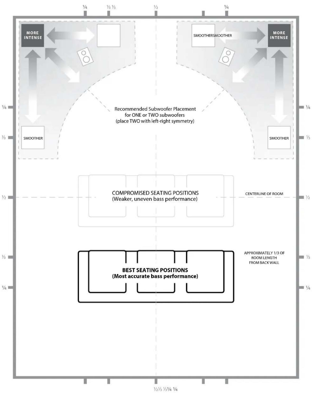
The moral of this mode story is to try and avoid seating positions in standing wave peak or dip regions. It is highly recommended that you place your listening chairs in areas where modal peaks and dips are moderate and do not reinforce one another. The two most obvious areas to avoid are those near the exact center of the room and those close to any of the room's walls.
Just as your listening seat can be in a peak or dip region, so can your subwoofer. When placed in a room corner, a subwoofer maximally excites the room's mode structure, creating the strongest output with the fewest dips. When the subwoofer is pulled away from a corner or wall, the room modes are excited less, which can alter the sound at your listening seat.
Be sure to experiment with both your listening seat position and subwoofer position to find the best solution. Careful experimentation usually leads to a superior sounding system. Use our setup suggestions (illustrated on the opposing page and the following pages) to get you started.
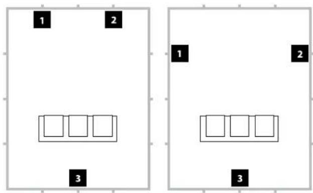
We recommend that you begin by placing your E-Sub in the front of the room, on the floor, near the front left or right speaker. Placing the E-Sub near solid walls will reinforce bass response and pulling it away from solid walls will decrease bass. Increasing the distance between the subwoofer and the walls may help to smooth upper bass response in some rooms.
We recommend that you avoid placing the E-Sub near windows to prevent rattling and sound transmission to the outside world.

If you are planning to install your E-Sub inside a cabinet, please refer to the guidelines on page 8.
Recommended Subwoofer Placement Options for for One or Two E-Subs
flowchart
graph TD
    A["MORE INTENSE"] --> B["SMOOTHER"]
    C["SMOOTHERSMOOTHER"] --> D["SMOOTHER"]
    E["MORE INTENSE"] --> F["Recommended Subwoofer Placement for ONE or TWO subwoofers (place TWO with left-right symmetry)"]
    G["BEST SEATING POSITIONS (Most accurate bass performance)"] --> H["COMPROMISED SEATING POSITIONS (Weaker, uneven bass performance)"]
    I["APPROXIMATELY 1/3 OF ROOM LENGTH FROM BACKWALL"] --> H
    J["CENTERLINE OF ROOM"] --> H
    K["1/2 1/3 1/4"] --> H
    L["1/2 1/3 1/4 1/4"] --> H
    M["1/4 1/4"] --> H
SPECIAL CONSIDERATIONS FOR BUILT-IN INSTALLATIONS
The E-Sub can be integrated into custom cabinetry by following a few simple guidelines.
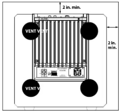
- Allow 4 inches (10 cm) of clear space behind the E-Sub's amp panel for adequate cooling and connector clearance.
- On all other sides (except the bottom), allow at least 2 inches (5 cm) clearance for adequate ventilation.
- While the E-Sub generally runs only warm during spirited operation, we do recommend that adequate heat vents are included in any custom cabinet which encloses the E-Sub. A pair of 3 inch (7.5 cm) diameter vents near the bottom of the cabinet and near the top of the cabinet, will allow cool air to circulate over the amp panel of your E-Sub subwoofer system keeping it cool and happy.
- Your E-Sub subwoofer is capable of moving substantial quantities of air. If the front of the E-Sub is covered by a custom grille, the grille must have AT LEAST 85 square inches (548 sq.cm.) of vent area for the e112, and AT LEAST 60 square inches (386 sq.cm.) for the e110. These areas are equal to the woofer cone area for each model and will ensure that the E-Sub's output is not choked by the custom cabinet.
Rear-view of cabinet install:
Using Two E-Subs
When using two E-Subs, try placement near the front corners of the room, at diagonally-opposite corners of the room, or at the center points of opposing walls as shown at right.
Experimentation with subwoofer and listener placement is recommended to achieve the best results – the benefits can be substantial.
High-resolution measurements and professional system calibration are recommended for the best possible results & system performance.
Recommended Subwoofer Placement Options for Two E-Subs
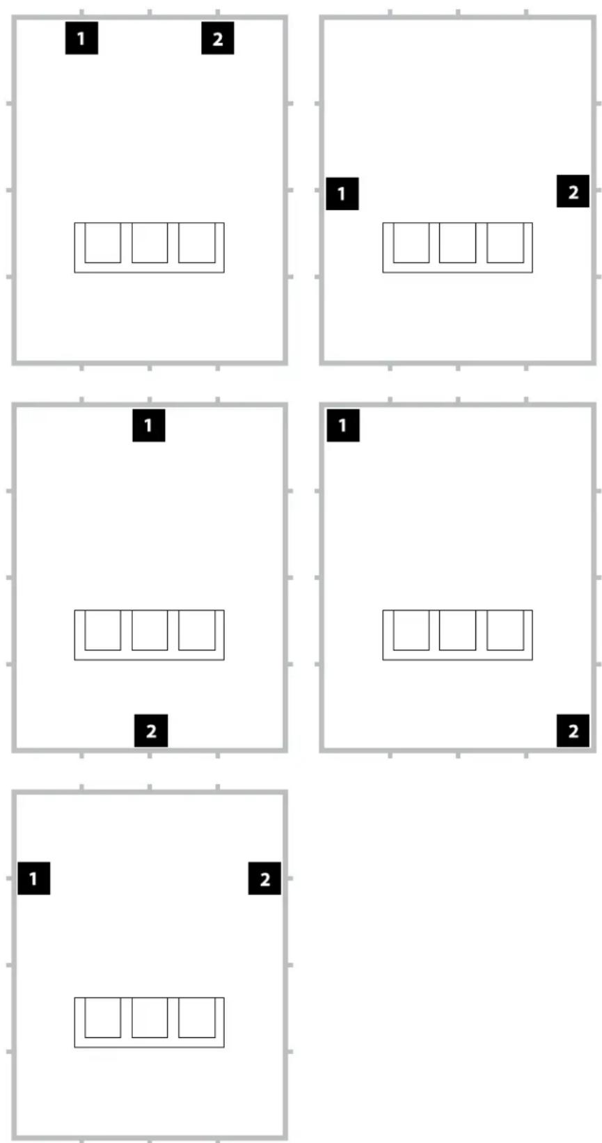
Recommended Subwoofer Placement Options for Three E-Subs
Recommended Subwoofer Placement Options for Four E-Subs
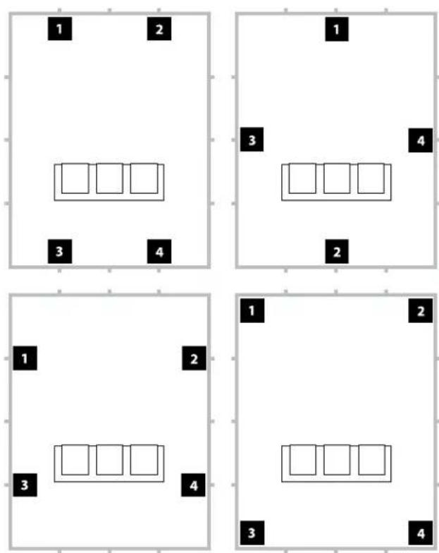
Using Three or Four E-Subs
Research indicates that the smoothest bass response for a large listening area can be achieved using four subwoofers, placing one at the midpoint of each of the four walls (although using two or three subwoofers can be almost as good).
Experimentation with subwoofer and listener placement is recommended to achieve the best results – the benefits can be substantial.
High-resolution measurements and professional system calibration are recommended for the best possible results & system performance.
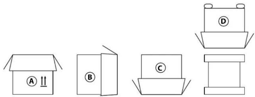
Unpack this box close to where the subwoofer will be placed. The subwoofer is PACKED upside down. This box must be flipped over CAREFULLY to remove the subwoofer and minimize effort.
IMPORTANT

IMPORTANT

UNPACKING YOUR E-SUB
Now that you have determined your E-Sub's position on the floor of your room, you can proceed with unpacking it near its intended location.
IMPORTANT! DUE TO THE WEIGHT OF THE E-SUB SUBWOOFER, PLEASE EXERCISE CAUTION WHILE UNPACKING AND POSITIONING IT TO PREVENT INJURY. IF POSSIBLE, ENLIST THE HELP OF A SECOND PERSON TO FACILITATE THE PROCESS. TO MINIMIZE THE RISK OF INJURY, BEND YOUR KNEES AND LIFT WITH YOUR LEGS, NOT YOUR BACK.
Detailed instructions on unpacking the subwoofer:
- Place the carton on the floor near its intended location in the room.
- Open the top of the carton (observe markings on carton) and remove the manual and power cord.
- The subwoofer is packed upside-down. Lift the styrofoam cap off the bottom of the subwoofer.
- Loosen the protective cloth cover to make later removal easier (do not remove at this time). When you open the cloth cover, you are looking at the bottom of the subwoofer cabinet.
- Replace the styrofoam cap you removed in Step 3 to protect the subwoofer's cabinet while flipping and unpacking the subwoofer in the following steps.
- Gently flip the box on its side, folding back the carton flaps to the outside.
- Holding the carton flaps back, gently flip the carton onto its top (open end).
- Pull the carton straight up until it clears the subwoofer and place to one side.
- Remove the top-most styrofoam cap and place this cap in the carton.
- Remove the plastic bag and place in the carton.
- Lift the subwoofer off the remaining styrofoam cap and place this cap in the carton.
- Remove the protective cloth cover and place in the carton.
IMPORTANT! PLEASE RETAIN ALL PACKAGING FOR SAFE TRANSPORTATION OF THE SUBWOOFER AND FOR ANY FUTURE SERVICE NEEDS.
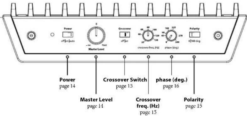
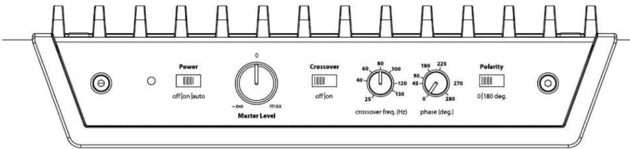
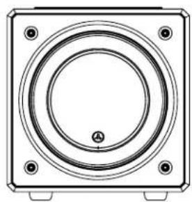
Top-Mounted Control Panel
The labeled Figure below depicts the top-mounted control panel of the E-Sub subwoofer.
The E110 and E112 have identical layouts.
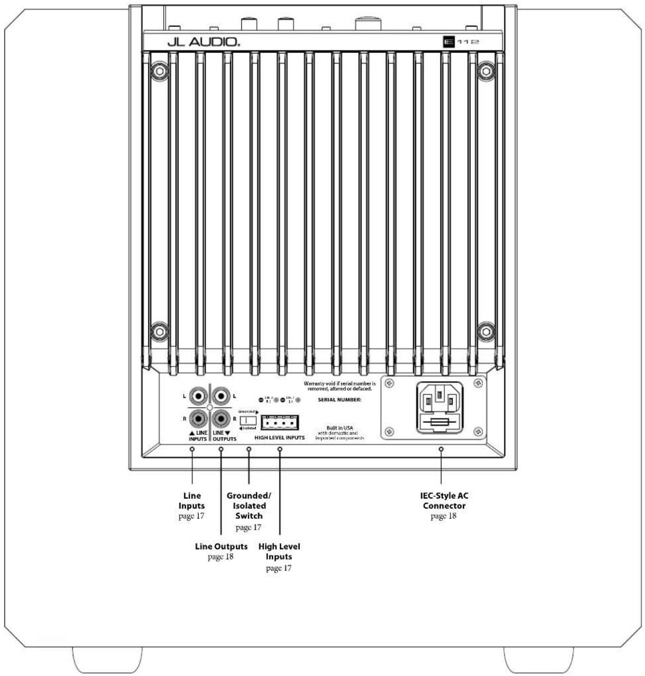
Rear Connection Panel (120V Model Shown)
The labeled Figure below depicts the rear panel of the E-Sub subwoofer.
The e110 and e112 have identical layouts.
TOP-MOUNTED CONTROLS IN DETAIL
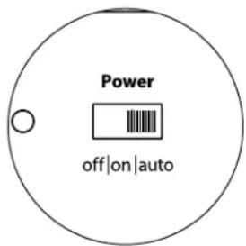
Top-Panel Power Switch and Indicator LED
The “Power” switch on the top panel determines the operational readiness of the E-Sub subwoofer and should be the only switch used to turn the E-Sub on and off during typical use.
The top-panel "Power" switch has three positions:
"Off": The E -Sub's internal power amplifier is powered down.
Indicator LED: red
In this stand-by state, a tiny amount of power is consumed (< 0.5 watt) to energize the E-Sub's soft turn-on circuitry.
"On": The E -Sub is fully operational.
Indicator LED: green
Power consumption will vary, depending on program material and level
"Auto": The E-Sub will power up its internal amplifier when it detects an audio signal at any of its inputs, and will power down the internal amplifier if no signal has been detected at its inputs for approximately thirty (30) minutes. While dormant, the E-Sub consumes a tiny amount of power (< 0.5 watt). Indicator LED: amber (dormant) / green (operational)
In the unlikely event that the Auto Turn-On feature is not sensitive enough for a particular system, use a Y-cable adaptor (one female to two male RCA type connectors) to split the incoming signal into both RCA inputs on the E-Sub. This will increase the input sensitivity by 6 dB. Please be aware that if there is significant noise entering the E-Sub's input, the E-Sub may not turn off as desired. If this happens, remove the Y-cable adaptor and/or look for the noise source in the upstream components.
The only way to completely power down an E-Sub is to unplug its AC Power Cord. Before disconnecting the power cord, always place the top-panel “Power” switch in the “off” position (to prevent damaging pops and transient noises).
Do not use a power strip switch, switched outlet or any other external switch to interrupt or engage power to an E-Sub in “auto” or “on” positions, as this will also result in undesirable and potentially damaging transient pops.
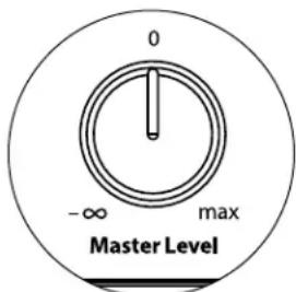
Master Level Knob
The “Master Level” Knob is used to set the output level of the E-Sub, relative to the rest of the audio system.
When rotated fully counter clockwise, the E-Sub's output will be fully muted. When at the "0" or straight up position, the level is at reference gain. When turned fully clockwise, the E-Sub's level is at its maximum sensitivity (loudest).

IMPORTANT
radar
| Position | Value | |---|---| | 0 | 90 | | 10 | 45 | | 20 | 130 | | 30 | 120 | | 40 | 40 | | 50 | 60 | | 60 | 80 | crossover freq. (Hz)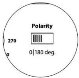
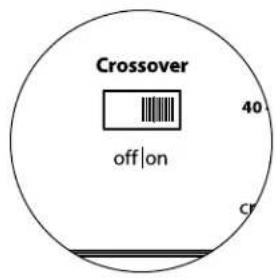
Crossover Switch
The “crossover” selector switch determines the operating mode of the E-Sub's built-in active crossover.
"Off" defeats the crossover filter, completely removing this circuit from the signal path and is most useful when using a receiver or preamp/processor's filters and bass-management features.
"On" activates the on-board active crossover. This crossover consists of a 24 dB/octave low-pass filter for signals feeding the E -Sub's internal amplifier, plus a 24 dB/octave high-pass filter feeding the "Line-Outputs" on the E -Sub's rear connection panel. This is most useful when integrating the E -Sub into a two-channel audio system.
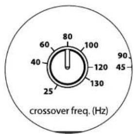
Crossover Frequency Knob
The “crossover freq. (Hz)” selector knob allows the user to choose the crossover frequency of the E-Sub's built-in, active crossover. It has no effect when the “crossover” switch is in the “off” position. The frequency is variable from 25 Hz (full counter-clockwise) to 130 Hz (full clockwise). 80 Hz is a commonly used filter frequency and usually serves as a good starting point for adjustments.
Polarity Switch
The “Polarity” switch allows the user to select between normal (0 deg) and reversed (180 deg) signal polarity. The “Polarity” switch will primarily affect the small frequency range around the crossover point between your subwoofer and satellite speakers.
Unlike the “phase (deg.)” control, which effectively adds time delay, the “Polarity” switch produces an instantaneous reversal of the signal’s amplitude peaks. For example, if at a given reference point a sine wave has an amplitude peak, by flipping the “phase (deg.)” switch you instantly convert that peak into a trough or amplitude dip. Because the effect of the “Polarity” switch is immediate, it compliments the operation of the “phase (deg.)” control and cannot be replaced by it.
When placing your E-Sub in the room, experiment with the "Polarity" switch before adjusting the "phase (deg.)" control. Either position of the "Polarity" switch may provide a smoother transition between your E-Sub and the satellite speakers. Use source material with good mid and upper bass content for evaluation.
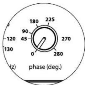
Phase Knob
The “phase (deg.)” control knob allows the user to adjust the timing of the subwoofer output relative to the main speakers. The “phase (deg.)” control will primarily affect the small frequency range around the crossover point between your subwoofer and satellite speakers. The “phase (deg.)” control’s degree labeling is referenced to 80 Hz, since this is the most common crossover point between satellite speakers and a subwoofer. Phase settings between 0 degrees (full counterclockwise rotation) and 280 degrees (full clockwise rotation) are possible.
Speaker, subwoofer, and listening seat positions vary greatly in home theater installations. Since physical positioning of speakers relative to the room boundaries and each other greatly affects the perceived quality of sound output, sometimes it is helpful to delay the subwoofer output. This is exactly what occurs when you turn the “phase (deg.)” control beyond 0 degrees.
Once your E-Sub has been placed in your listening room to give you the smoothest overall sound, and after you have determined the optimum “Polarity” switch position (see preceding section), experiment with the position of the “phase (deg.)” control. Using familiar source material with good mid and upper bass content, adjust the “phase (deg.)” control and listen for better defined mid-bass and a smoother transition between the subwoofer and satellite speaker systems. If no single setting sounds better than another, leave the “phase (deg.)” control at 0 degrees.
The Left and Right inputs on the E-Sub are internally summed to a single mono channel.

CONNECTING YOUR E-SUB(S)
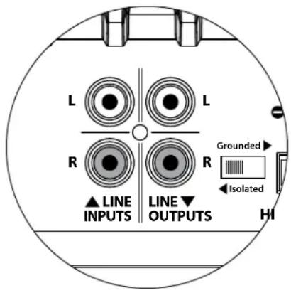
Line Inputs
The E -Sub features individual, left and right, unbalanced RCA-type input connectors. These are the most commonly used connectors for home audio applications.
For systems with a mono subwoofer or "LFE" channel connection, only one RCA-type jack will be used (Left or Right). This method applies to most modern multi-channel receivers and preamplifier / processors.
Separate left and right RCA-type input jacks are provided for systems without a dedicated mono subwoofer connection. This typically applies to two-channel audio equipment. In a two-channel application, you must supply separate left and right inputs to a single E-Sub in order to have high-pass filtered, stereo outputs from its Line Outputs. The E-Sub will automatically sum the left and right inputs to feed its internal subwoofer amplifier.
RCA-type connectors (one for each channel):
Tip: Positive
Sleeve: Negative
Input Impedance: 10 kΩ
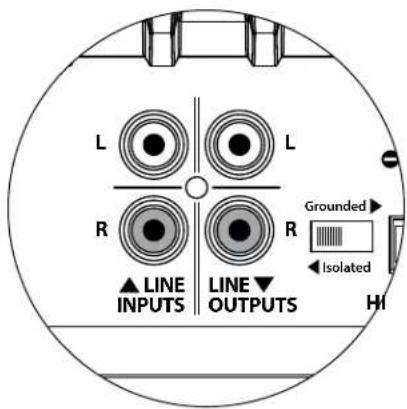
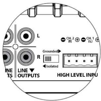
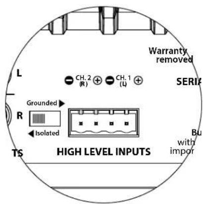
"Grounded / Isolated" Switch
This feature is included to deal with the signal grounding issues often encountered in home theater systems when several components from different manufacturers are interconnected. The “Grounded / Isolated” Input Mode switch on the rear connection panel alters only the “Line Inputs” and is designed to facilitate a quiet, hum-free connection to your audio or home theater system. This switch has no effect on signals connected to the “High-Level Inputs”.
The E-Sub ships with this switch in the “Isolated” position. If, with all system components connected and turned on (but no source material playing), you hear a continuous low-frequency hum through your E-Sub, flip this switch to the “Grounded” position and evaluate the difference in the noise level. Use whichever switch position provides the least hum or noise.
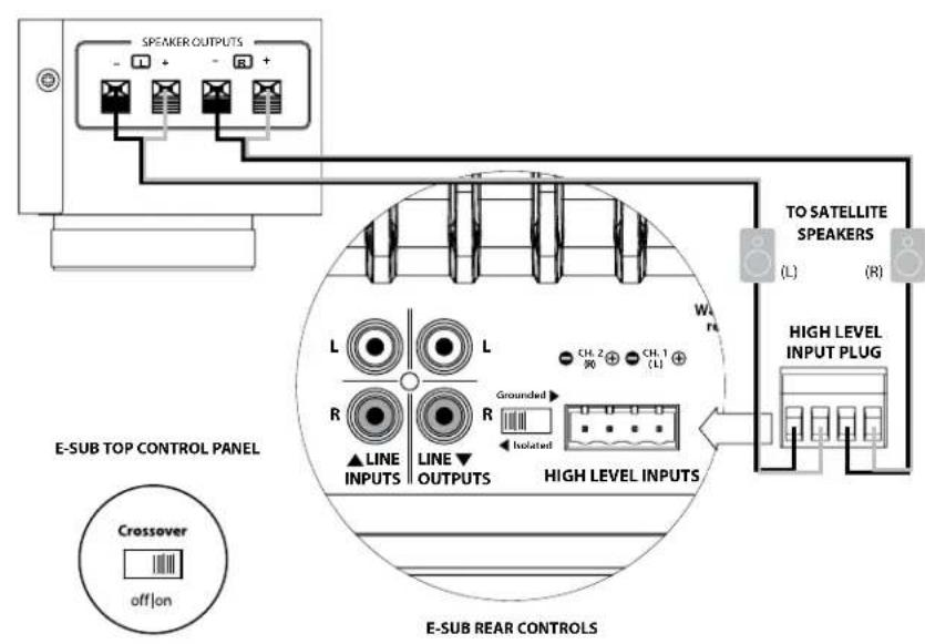
High Level Inputs
This feature is included for convenience when needing to connect the E-Sub to a receiver or integrated amplifier that only offers speaker level outputs. It is not the preferred method when a line-level signal is available.
To use the "High Level Inputs" feature, simply connect the speaker outputs of the receiver or integrated amplifier to the "High Level Input" plug of the E -Sub, in parallel with the main speakers. The main speakers will remain full-range in this application and their sound will not be affected by the connection to the E -Sub.
The “High Level Input” consists of an input connector and removable plug with captured-wire receptacles. Standard speaker cable, up to 12 AWG (3 mm 2 ), can be used and connected to the removable plug by backing out each set screw, inserting the bared end of each speaker wire, taking care not to short any wire to another, and tightening the set screw. Connections are as follows:
"High Level Input" Connector (from left to right):
1: Right Channel Negative
2: Right Channel Positive
3: Left Channel Negative
4: Left Channel Positive
Input Impedance: 4.3 kΩ
Line Outputs
The E-Sub features individual, left and right, unbalanced RCA-type output connectors to feed a second subwoofer or an amplifier powering main stereo speakers. The “Line Outputs” can be used in two distinct ways, depending on your system’s configuration.
Crossover On: High-Pass Filtered Outputs
When the E-Sub's on-board crossover is engaged (“Crossover” switch in the “on” position - page 15), the “Line Outputs” will deliver a high-pass filtered signal according to the frequency selected by the “crossover freq. (Hz)” knob. This creates a true, two-way, 24 dB/octave, Linkwitz-Riley crossover between the E-Sub and the main stereo speakers.
Please note that you must supply separate left and right channel stereo inputs to the E-Sub in order to have high-pass filtered, stereo outputs from its “Line Outputs”. If you supply only one channel of input to the E-Sub, only the line output corresponding to the input with signal will deliver a high-pass filtered signal (the other line output will have no signal). If you are using two E-Subs in a two-channel system, you can assign one E-Sub to the left stereo channel and the other E-Sub to the right stereo channel, using only one “Line Input” and one “Line Output” per E-sub.
Crossover Off: Pass-Through Subwoofer Output
When the E-Sub's on-board crossover is defeated (“Crossover” switch in the “off” position - page 15), the “Line Outputs” will deliver a pass-through, buffered signal that is identical to the signal feeding the E-Sub's “Line Inputs”. This is very useful for passing a subwoofer signal from one E-Sub to another E-Sub in a multi-subwoofer installation.
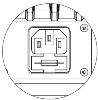
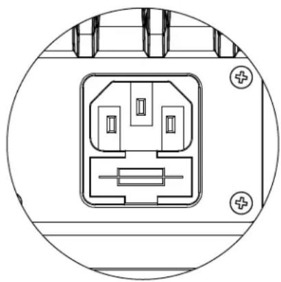
AC Power Connector
The IEC-style AC cord receptacle receives the heavy-gauge, 6 ft. (1.8 m) long, power cord included with your E-Sub subwoofer. E-Subs sold in different parts of the world are configured for each market's electrical system and include appropriate plugs on their power cords. Please note the voltage markings next to the AC Connector and make sure you are only powering the E-Sub from a receptacle that matches these markings. Do not use any AC power cord other than the one supplied with the E-Sub.
The E-Sub subwoofer is a very powerful device and can draw a lot of current. If too many components are connected with an E-Sub subwoofer to one electrical outlet, you risk tripping a household circuit breaker during very demanding program material. If this happens, split the E-Sub and other components between two AC electrical circuits.

natural_image
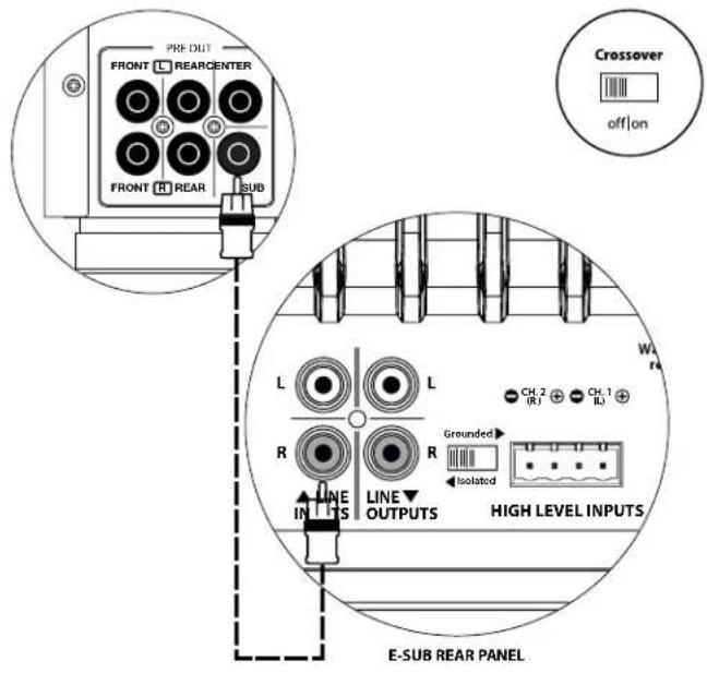
Technical line drawing of an electrical connector with mounting holes and a central internal component (no text or symbols)SYSTEM CONNECTION DIAGRAM 1: One E-Sub to Home Theater Receiver or Home Theater Preamp/Processor
Most home theater receivers and preamp/processors provide a single (mono) subwoofer line-level output.
When connecting a mono subwoofer output to your E-Sub, you only need to connect to one of the E-Sub's "Line Inputs" (Left or Right). Use a good-quality audio interconnect cable with RCA-type connectors.
In most cases, you will use the bass management/crossover features of the receiver or preamp/processor. This requires that the E-Sub's "Crossover" switch is placed in the "Off" position.
RECEIVER / PROCESSOR
E-SUB TOP CONTROL PANEL
WARNING

WARNING! TURN OFF THE E-SUB(S) AND ALL OTHER EQUIPMENT IN THE SYSTEM BEFORE MAKING OR CHANGING ANY CONNECTIONS!
WARNING! TURN OFF THE E-SUB(S) AND ALL OTHER EQUIPMENT IN THE SYSTEM BEFORE MAKING OR CHANGING ANY CONNECTIONS!
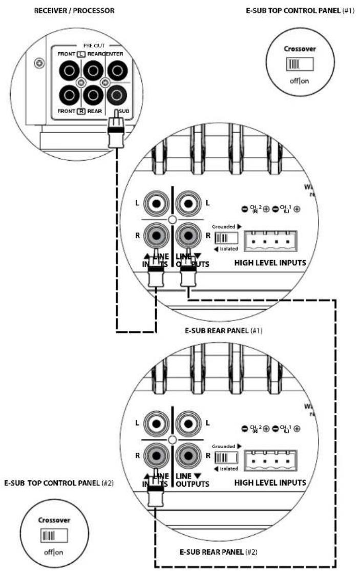
SYSTEM CONNECTION DIAGRAM 2: Multiple E-Subs to Home Theater Receiver or Home Theater Preamp/Processor
Most home theater receivers and preamp/processors provide a single (mono) subwoofer line-level output.
To greatly simplify the connection of multiple subwoofers in a single home theater system, E-Subs include a pass-through line output feature. This allows an input signal connected to one E-Sub to be passed from that E-Sub to a second one, and from the second E-Sub to a third, etc.
When connecting a mono subwoofer output to multiple E-Subs, you only need to connect to one of each E-Sub's "Line Inputs" (Left or Right). Run an audio interconnect cable from the receiver/pre-pro's subwoofer output to one "Line Input" of the first E-Sub in the system. Then run a second audio cable from that E-Sub's corresponding "Line Output" to one "Line Input" of the next E-Sub in the system, as shown in the diagram. Additional E-Subs can be added using the same method.

IMPORTANT
You must turn the E-Sub's "Crossover" off to use the pass-through signal feature, allowing the receiver/pre-pro to perform crossover/bass-management functions. Make sure the "Crossover" switch on the top control panel of the E-Sub is in the "off" position to use this connection method.
Alternative Method:
If running cables from one E-Sub to the next is not practical due to the physical layout of the E-Subs relative to the receiver/pre-pro, you can use a Y-Adaptor cable (splitter) to split the receiver/pre-pro output signal to multiple audio interconnect cables, each feeding a separate E-Sub.
Some receivers and preamp/processors offer multiple subwoofer outputs, which can also be used to connect multiple E-Subs. Refer to the manual of your receiver/pre-pro for details.

WARNING
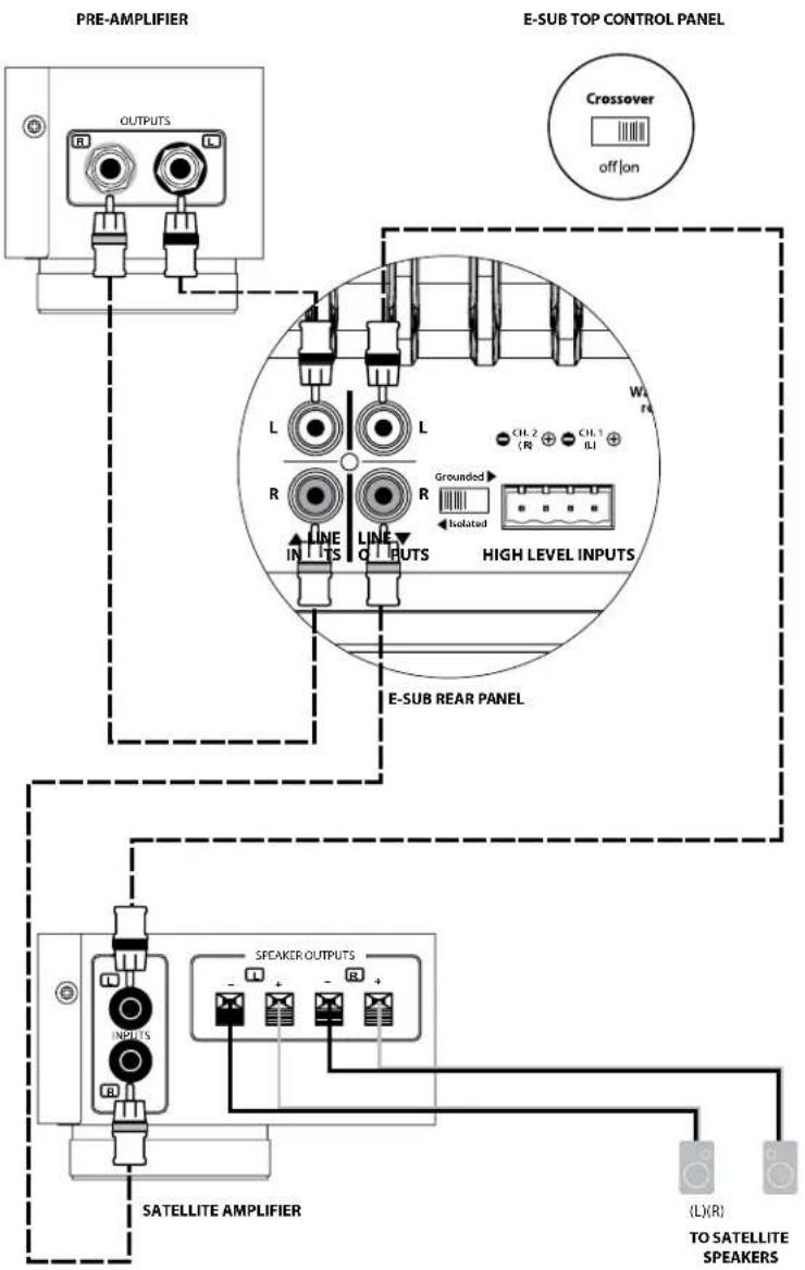
SYSTEM CONNECTION DIAGRAM 3: One E-Sub in Mono to Two-Channel Audio System
When connecting a single E-Sub in mono to a two-channel audio system you will use both the "Left" and the "Right" "Line Inputs" of the E-Sub and you will engage the E-Sub's active crossover by selecting the "on" position on the "Crossover" switch located on the top control panel.
The internal active crossover will apply low-pass filtering to feed the subwoofer's internal amplifier with a summed L+R signal. It will also high-pass filter the input signal and send it to the satellite amplifier via the "Line Outputs" jacks. This creates a true two-way crossover that greatly improves the overall performance of your audio system by preventing the subwoofer and satellite speakers from playing the same frequency range, and by liberating the satellite amplifier and speakers from the burden of reproducing power hungry, distortion-inducing low-frequencies.
Use good-quality audio interconnect cables with RCA-type connectors to make these connections.
WARNING

WARNING! TURN OFF THE E-SUB(S) AND ALL OTHER EQUIPMENT IN THE SYSTEM BEFORE MAKING OR CHANGING ANY CONNECTIONS!
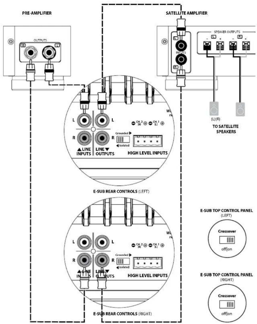
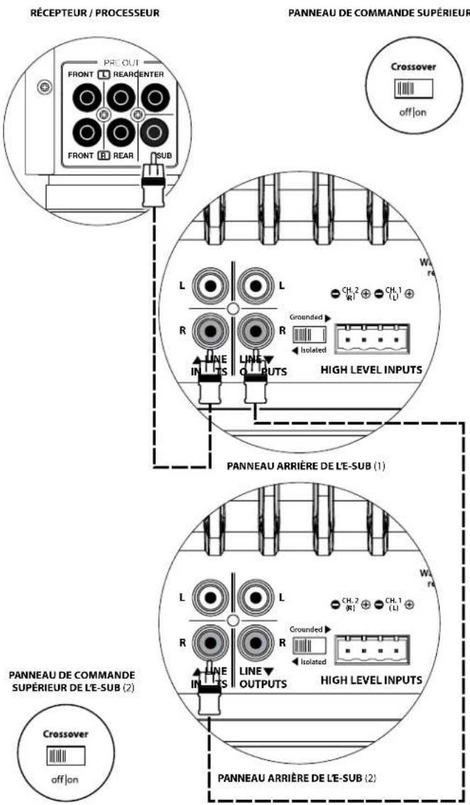
SYSTEM CONNECTION DIAGRAM 4: Two E-Subs in Stereo to Two-Channel Audio System
When connecting two E-Subs in stereo to a two-channel audio system you will assign one E-Sub to the left channel and the other one to the right channel. You will engage each E-Sub's active crossover by selecting the "on" position on the "Crossover" switch located on the top control panel.
The internal active crossover will apply low-pass filtering to feed the subwoofer's internal amplifier. It will also high-pass filter the input signal and send it to the satellite amplifier via the "Line Outputs" jack corresponding to the input channel used. This creates a true two-way crossover that greatly improves the overall performance of your audio system by preventing the subwoofer and satellite speakers from playing the same frequency range, and by liberating the satellite amplifier and speakers from the burden of reproducing power hungry, distortion-inducing low-frequencies.
You will only use one "Line Input" on each E-Sub (left or right). First, connect the left output of your preamplifier to the "Line Input" of the E-Sub designated as the left subwoofer, and then connect that E-Sub's "Line Output" to the left input of your satellite amplifier.
Then, connect the right output of your preamplifier to the "Line Input" of the E-Sub designated as the right subwoofer, and then connect that E-Sub's "Line Output" to the right input of your satellite amplifier.
Use good-quality audio interconnect cables with RCA-type connectors to make these connections.
WARNING! TURN OFF THE E-SUB(S) AND ALL OTHER EQUIPMENT IN THE SYSTEM BEFORE MAKING OR CHANGING ANY CONNECTIONS!
WARNING
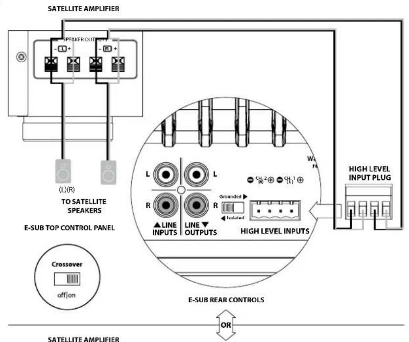
SYSTEM CONNECTION DIAGRAM 5: Connecting one E-Sub to a Receiver via the High-Level Inputs
The E-Sub features high-level inputs designed to accept the output of an amplified source, such as a stereo receiver's speaker outputs. The use of this feature is only recommended when no suitable line-level signal is available.
When connecting a single E-Sub in mono to a two-channel receiver's speaker outputs, you will use both the Left and Right connections on the "High-Level Inputs" plug of the E-Sub. Use good-quality speaker cables (up to 12 AWG / 3 mm²) to make these connections. Make sure you capture all the wire strands and do not allow any of these wires to short together.
You can make the connections to the E-Sub inputs at the receiver's output terminals, or at the main speakers, whichever is more convenient. On receivers with A/B speaker circuit selectors, you can connect the E-Sub to the "B" outputs, giving you the ability to easily switch the subwoofer's signal on and off with the receiver's speaker circuit selector switch.
The E-Sub's input section will sum the left and right inputs to mono and apply low-pass filtering to feed the subwoofer's internal amplifier if the E-Sub's "Crossover" is switched "on".
Because the main speakers are being fed in parallel with the connection to the E-Sub's inputs, they will only operate as full-range speakers. Any adjustment of the "crossover" frequency" knob will only affect the sound of the E-Sub, not the main speakers.
WARNING

WARNING! TURN OFF THE E-SUB(S) AND ALL OTHER EQUIPMENT IN THE SYSTEM BEFORE MAKING OR CHANGING ANY CONNECTIONS!
RECOMMENDED SETUP PROCEDURES
1) Preparation for Setup Process: 24-25
2) Level Setting: 26
3) Polarity/Phase Adjustment: 26
4) Experiment with Location: 26
PREPARATION FOR SETUP:
Please confirm the following system settings before beginning the setup process. This will ensure a neutral starting point and an effective setup of your subwoofer system.
On your Home Theater Receiver or Preamp/Processor:
Before beginning setup of your E-Sub subwoofer system, we recommend that you set your receiver or preamp/processor as follows (please turn off all E-Subs in the system via their front panel power switches prior to making these adjustments):
1. Speaker Size
In the speaker setup menu of your receiver or preamp/processor, set up all of your high-frequency speakers as "small" with a crossover point of 80 Hz. This will send ALL bass to the E-Sub(s).
2. Speaker Distance
In the speaker setup menu, properly set all speaker distances to the primary listening seat, including the subwoofer's distance. Use a tape measure to determine these distances (time coherence is important.) If multiple E-Subs are being used, average their distances to the primary listening seat and use that number to set the subwoofer distance.
3. Subwoofer Level
Set the subwoofer level in the receiver or preamp/processor to "0" or its middle position.
4. Tone Controls / Equalizers
Set all tone controls to "0" and defeat all equalizer features.
On your Active Crossover or Bass Management Processor:
If you are using an active crossover or bass-management processor, we recommend that you set it as follows before beginning setup of your E-Sub subwoofer system (please turn off all E-Subs in the system prior to making these adjustments):
1. Crossover Filter Frequency
Select a low-pass filter frequency of 80 Hz (24dB/octave slope, if given an option)
2. Subwoofer Output Level
Set the subwoofer output level to "0" or its middle position.
On the E-Sub's Top Panel:
Please turn off the home theater receiver or preamp/processor to make these adjustments.
1. "Power" Switch
Flip each E-Sub's "Power" switch to the "On" position.
2. "Crossover" Switch and "crossover freq. (Hz)" knob
If your home theater receiver/processor is handling bass management (speakers set on “small”), or if you are using an outboard crossover/bass-management processor, flip the master E-Sub’s “Crossover” switch to “off.” If you intend to use the E-Sub’s built-in, active crossover, select the “on” position and set the “Crossover Freq. (Hz)” knob to the “80 Hz” position.
3. "Polarity" Switch
Flip the "Polarity" switch to "0".
4. "phase (deg.)" Knob
Rotate the "phase (deg.)" knob to "0" degrees
RECOMMENDED SETUP PROCEDURES (continued)
Subwoofer System Setup:
Once you have set the controls on your home theater receiver or preamp/processor and on your E-Sub(s) to the settings recommended on pages 24 and 25, you are ready to begin setting up your E-Sub for optimum performance.
1) Level Setting
Using familiar music or movie material with deep bass content, adjust the subwoofer level to blend with the other speakers using your receiver or preamp / processor's subwoofer level control.
In the unlikely event that the subwoofer level control in your receiver or preamp/processor cannot be turned up enough to level match the E-Sub, return that control to “0”. Then, use the E-Sub’s “Master Level” control to level match the subwoofer with the other speakers.
For more detailed information on your E-Sub's level setting controls, please refer to the "Master Level" section on page 14 of this manual.
2) Polarity and Phase Adjustment
It is often helpful to have a second person operating these controls so that you can easily hear the changes from the primary listening seat.
Listening to familiar source material (preferably music with good upper bass and midbass response), flip the “Polarity” switch from “0” to “180” and listen for differences. The correct setting will sound most natural with the best upper bass punch and articulation. If both sound similar, choose “0”.
Once Polarity is set, use the same music material to audition different “Phase” control settings and choose the one that further enhances the upper and midbass response. If you cannot hear a difference, set the control to “0.”
3) Experiment with alternative subwoofer locations (if necessary).
If you are satisfied with the basic performance of your subwoofer, you are ready to move on to the next step. If not, we recommend that you experiment with the position of your subwoofer until you are pleased with its basic performance. Experimenting with placement is KEY to a superior sounding system. Moving the subwoofer just a few feet can have a significant effect on the smoothness of the bass. For each new position, start with the polarity and phase controls at “0” and repeat the setup process beginning with Step 1.
This completes the basic setup process! You can achieve further improvements through the correct use of processing built into your receiver or preamp/processor. Consult with your JL Audio authorized retailer if you require further setup assistance.
IMPORTANT! WRITE DOWN ALL SETTINGS PERFORMED IN STEPS 1-3 FOR FUTURE REFERENCE. PAGE 30 IS PROVIDED FOR INSTALLATION NOTES.

IMPORTANT
FREQUENTLY ASKED QUESTIONS
Can I place objects on my subwoofer?
We do not recommend placing any items on the subwoofer cabinet as they may vibrate, causing undesirable noise and possible damage to the finish. Under no circumstances should any object containing liquid be placed on the E-Sub cabinet.
Is the E-Sub magnetically shielded?
NO. To avoid magnetic distortion with certain television types, place the E-Sub at least 3-4 feet (1 - 1.5m) from your screen. If you notice any discoloration in the picture, try moving the subwoofer further away until these artifacts disappear.
Will my electric bill be high if I leave the E-Sub in "Auto" mode?
When in “Auto” mode, the E-Sub’s amplifier is only powered up when a significant signal is detected on the inputs. When powered down, only “housekeeping” circuits remain on, which draw negligible amounts of power from the wall (less than 0.5 watt).
Should I unplug the E-Sub during a thunderstorm or extended absence?
YES. You should unplug your E-Sub during (or before) thunderstorms. This will prevent any possible damage from voltage spikes due to lightning. In these conditions, it's a good idea to unplug all of your audio/video components. Unplugging your audio/video equipment before an extended absence is highly recommended, in the event that a storm event occurs during that absence.
Is it safe to use my E-Sub outdoors, in a sauna or on a pool deck?
NO. The E-Sub is only designed for operation in dry, indoor environments.
CLEANING YOUR E-SUB
Dust your E-Sub subwoofer's cabinet using a clean, soft microfiber cloth or feather duster. Microfiber cloths are commonly available where automotive detailing supplies are sold.
Gloss-black models:
Light smudges can generally be wiped off with a clean microfiber cloth. For more stubborn smudges, polish and protect the finish using a high-quality automotive wax and a microfiber cloth, both available wherever automotive detailing supplies are sold.
Vinyl-Veneer models:
Light smudges can generally be wiped off with a clean microfiber cloth. For more stubborn stains, clean the cabinet's surface with a damp cloth.
Never use a polish that contains harsh solvents or abrasives as these may permanently damage the finish. Never use furniture polish or any oil-based product on your E-Sub. Never use solvents or aggressive cleaning agents on your E-Sub. When in doubt, test the cleaning product on the underside of the cabinet and let it sit for several days before committing to its use on visible portions of the cabinet.
TROUBLESHOOTING
No sound from subwoofer.
- Verify that E-Sub is plugged in, turned "ON" & that the top-panel LED is green. If the E-Sub will not power up, check the circuit breaker that feeds its outlet, or the AC power cord.
- Verify that your receiver's subwoofer settings have not changed.
- If your other speakers play, but the E-Sub does not, try changing the cable that connects the E-Sub to the system.
- If the problem persists, call your dealer or JL Audio Technical Support for assistance.
The bass level has changed.
Make sure your level settings on the E-Sub's "Master Level" knob and in your receiver/preamp/processor have not changed.
Hums or other unusual noises from your E-Sub
- See discussion of "Grounded/Isolated" switch on page 17 of this manual, especially if any upstream components, cables, etc., have recently changed.
- Turn off the E-Sub, disconnect all its input and output signal cables; then turn the E-Sub back on. If the noise disappears, the noise is being caused elsewhere in your system.
Bass sounds "muddy" or "too heavy".
- Decrease the overall subwoofer level.
- Verify your receiver's subwoofer settings.
- Try a different subwoofer location or main listening seat location. Changing one or the other can have a HUGE effect on how your system sounds. See the placement discussion on pages 6-10 of this manual.
Your E-Sub is clearly audible outside of your house.
- Revisit the "Master Level" setting on your E-Sub(s) or your home theater receiver/preamp/processor.
- Inquire with your JL Audio dealer about noise isolation strategies.
- Move the E-Sub away from windows.
Angry neighbors knocking at your door.
Invite them in and offer them a beverage.
natural_image
Front view of a rectangular electronic device with a top connector (no text or symbols visible)TOP
natural_image
Simple line drawing of a rectangular object with four corner holes, no text or symbols present.BOTTOM

natural_image
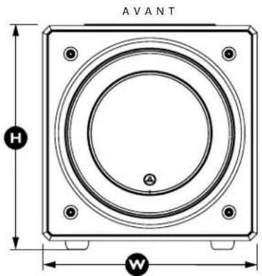
Front view of a portable electronic device with vertical bars and control buttons (no visible text or symbols)BACK
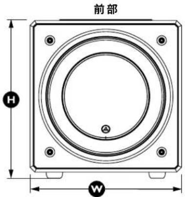
SIDE WITH GRILLE
natural_image
Simple line drawing of a rectangular container with a labeled dimension D (no text or symbols on the diagram itself)| Specifications | E110E-Sub powered subwoofer | E112E-Sub powered subwoofer |
| Enclosure Type: Sealed Sealed | ||
| Driver: Single 10 inch (nominal diameter) Single 12 inch (nominal diameter) | ||
| Frequency Response (anechoic): | 25-116 Hz (±1.5dB)-3 dB at 23 Hz / 120 Hz-10 dB at 18 Hz / 165 Hz | 22-118 Hz (±1.5dB)-3 dB at 21 Hz / 120 Hz-10 dB at 17 Hz / 153 Hz |
| Effective Piston Area: | 58.78 sq. in. (0.0379 sq. m) | 84.4 sq. in. (0.0545 sq. m) |
| Effective Displacement: | 131 cu. in. (2.1 liters) | 235 cu. in. (3.9 liters) |
| Amplifier Power: | 200 watts RMS short term 1500 watts RMS short term | |
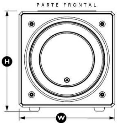
| Dimensions: (H) Height x (W) Width x (D) DepthHeight Dimensions include feet | 14.24 in. x 13.3 in. x 16.51 in,362 mm x 343 mm x 419 mm | 16.23 in. x 15.50 in. x 18.39 in,412 mm x 394 mm x 467 mm |
| Net Weight: | 52.7 lbs. (23.3 kg) 73.5 lbs. (33.3 kg) | |
FEATURES
Unbalanced Inputs:
Stereo or Mono (two RCA jacks)
High-Level Inputs:
Removable 4-Pole plug and connector
Line Outputs:
Stereo or Mono (two RCA jacks)
Master Level Adjustment:
Variable from full mute to +15dB over reference gain
Power Modes:
Off, On or Automatic (Signal-Sensing)
Active Crossover:
24 dB per octave, Linkwitz-Riley, variable from 25 Hz – 130 Hz, defeatable
Polarity:
0 or 180 degrees
Phase:
Variable from 0 - 280 degrees, referenced to 80 Hz
Power Supply:
Regulated PWM Switching Type
Amplifier Topology:
Class D Switching Type

JLAUDIO
natural_image
Technical line drawing of a square speaker or antenna with concentric rings and mounting holes (no text or symbols)e112 e110

natural_image
Technical line drawing of a square speaker or antenna with concentric rings and mounting holes (no text or symbols)DÉCLARATION DE CONFORMITÉ FCC

BRANCHEMENT DE VOTRE / VOS APPAREIL(S) E-SUB
Entrées ligne
natural_image
Technical line drawing of an electrical connector with mounting holes and a central internal component (no text or symbols)AVERTISSEMENT

AVERTISSEMENT ! ÉTEIGNEZ LE(S) APPAREIL(S) E-SUB ET TOUS LES AUTRES COMPOSANTS DU SYSTÈME AVANT D' EFFECTUER OU DE CHANGER DES CONNEXIONS !
AVERTISSEMENT ! ÉTEIGNEZ LE(S) APPAREIL(S) E-SUB ET TOUS LES AUTRES COMPOSANTS DU SYSTÈME AVANT D' EFFECTUER OU DE CHANGER DES CONNEXIONS !
natural_image
Simple line drawing of a rectangular container with a top handle and side supports (no text or symbols)DESSUS

natural_image
Simple line drawing of a rectangular object with four corner holes, no text or symbols present.DESSOUS

natural_image
Front view of a rectangular electronic device with vertical bars and control buttons (no text or symbols visible)ARRIÈRE
CÔTÉ AVEC GRILLE

natural_image
Simple line drawing of a rectangular container with a labeled dimension D (no text or symbols on the diagram itself)natural_image
Technical line drawing of a square speaker or antenna with concentric rings and mounting holes (no text or symbols)e112 e110
natural_image
Technical line drawing of a square speaker or antenna with concentric rings and mounting holes (no text or symbols)Line Outputs High Level
Página 18 Inputs
Página 17
CONTROLES SUPERIORES EN DETALLE

Interruptor "Grounded/Isolated"

natural_image
Technical line drawing of an electrical outlet with internal components and mounting holes (no text or symbols)- Interruptor "Crossover" y perilla "crossover freq. (Hz)"
- Interruptor "Polarity"
natural_image
Front view of a rectangular electronic device with a top connector (no text or symbols visible)PARTE SUPERIOR

natural_image
Simple line drawing of a rectangular object with four corner holes, no text or symbols present.BASE

natural_image
Front view of a rectangular electronic device with vertical bars and control buttons (no text or symbols visible)PARTE TRASERA
LATERAL CON REJILLA

natural_image
Simple line drawing of a rectangular container with a labeled dimension D (no text or symbols on the diagram itself)natural_image
Technical line drawing of a square speaker or antenna with concentric rings and mounting holes (no text or symbols)e112 e110

natural_image
Technical line drawing of a square speaker or antenna with concentric rings and mounting holes (no text or symbols)Bedienungsanleitung
VRC-Vented Reinforcement Collar
Engineered Lead-Wire System
AUSPACKEN IHRES E-SUB
DAS OBERE BEDIENFELD IM DETAIL

ANSCHLIESSEN IHRES E-SUB
Line-Eingänge
natural_image
Technical line drawing of an electrical connector with mounting holes and a central socket (no text or symbols)Alternative Methode:
natural_image
Front view of a rectangular electronic device with a top connector (no text or symbols visible)OBERSEITE

natural_image
Simple line drawing of a rectangular object with four corner holes, no text or symbols present.UNTERSEITE

natural_image
Front view of a rectangular electronic device with vertical bars and control buttons (no text or symbols visible)RÜCKSEITE

SEITE MIT GITTER

natural_image
Simple line drawing of a rectangular frame with a labeled dimension D (no text or symbols beyond the label)natural_image
Technical line drawing of a square speaker or antenna with concentric rings and mounting holes (no text or symbols)e112 e110
natural_image
Technical line drawing of a square speaker or speaker with concentric rings and mounting holes (no text or symbols)TECNOLOGIE JL AUDIO INCLUSE NEI SUBWOOFER E-Sub
radar
| Position | Value | |---|---| | 0 | 80 | | 1 | 60 | | 2 | 40 | | 3 | 120 | | 4 | 130 | | 5 | 90 | | 6 | 45 | | 7 | 25 | The label 'crossover freq. (Hz)' appears below the gauge perimeter.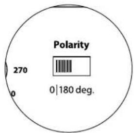
COLLEGAMENTO DELL'E-SUB
Ingressi di linea

natural_image
Technical line drawing of an electrical connector with mounting holes and a central internal component (no text or symbols)SCHEMA DI COLLEGAMENTO DELL'IMPIANTO 1:
ATTENZIONE! SPEGNERE GLI/L'E-SUB E TUTTE LE ALTRE APPARECCHIATURE NELL'IMPIANTO PRIMA DI REALIZZARE O MODIFICARE EVENTUALI COLLEGAMENTI!


ATTENZIONE! SPEGNERE GLI/L'E-SUB E TUTTE LE ALTRE APPARECCHIATURE NELL'IMPIANTO PRIMA DI REALIZZARE O MODIFICARE EVENTUALI COLLEGAMENTI!
ATTENZIONE! SPEGNERE GLI/L'E-SUB E TUTTE LE ALTRE APPARECCHIATURE NELL'IMPIANTO PRIMA DI REALIZZARE O MODIFICARE EVENTUALI COLLEGAMENTI!

SCHEMA DI COLLEGAMENTO DELL'IMPIANTO 4:
natural_image
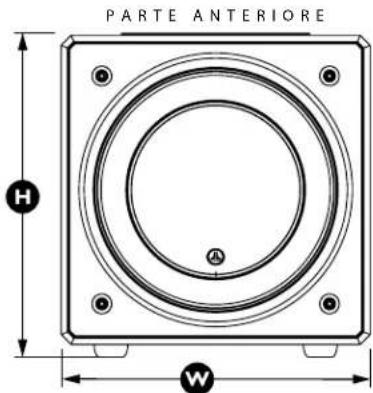
Simple line drawing of a rectangular container with a top handle and side supports (no text or symbols)PARTE SUPERIORE
natural_image
Simple line drawing of a rectangular object with four corner holes, no text or symbols present.PARTE INFERIORE
natural_image
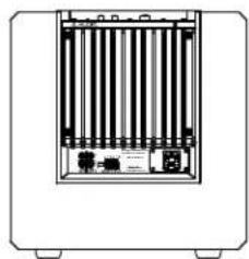
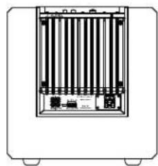
Front view of a rectangular electronic device with vertical bars and ports (no visible text or symbols)PARTE POSTERIORE
LATO CON GRIGLIA

natural_image
Technical line drawing of a rectangular enclosure with base and top dimensions labeled (no text or symbols beyond 'D' label)natural_image
Technical line drawing of a square speaker or antenna with concentric rings and mounting holes (no text or symbols)e112 e110
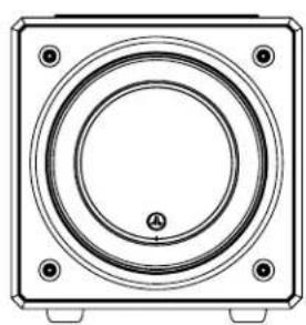
natural_image
Technical line drawing of a square speaker or audio component with concentric rings and mounting holes (no text or symbols)用户手册
重要安全说明

连接 E-Sub
线路输入

natural_image
Technical line drawing of an electrical outlet with internal components and terminal labels (no text or symbols)系统连接图 1:
natural_image
Simple line drawing of a rectangular container with a top handle and side supports (no text or symbols)顶部

natural_image
Simple line drawing of a rectangular object with four corner holes and a textured top surface (no text or symbols)底部
natural_image
Front view of a vertical panel with internal bars and a small inset device (no text or symbols visible)后部
带格栅的侧面

natural_image
Simple line drawing of a rectangular container with a side support and base, labeled 'D' at the bottom (no text or symbols on the diagram itself)- IMPORTANT SAFETY INSTRUCTIONS
- CAUTION
- FCC COMPLIANCE STATEMENT
- TABLE OF CONTENTS
- INTRODUCTION
- JL AUDIO TECHNOLOGIES INCLUDED IN E-Sub SUBWOOFERS
- DMA-Optimized Motor System
- VRC-Vented Reinforcement Collar
- Floating-Cone™ Attach Method
- Engineered Lead-Wire System (U.S. Patent #7,356,157)
- PRODUCT OVERVIEW
- PLACING YOUR E-SUB IN YOUR LISTENING ROOM:
- SPECIAL CONSIDERATIONS FOR BUILT-IN INSTALLATIONS
- Using Two E-Subs
- Using Three or Four E-Subs
- UNPACKING YOUR E-SUB
- Detailed instructions on unpacking the subwoofer:
- Top-Mounted Control Panel
- Rear Connection Panel (120V Model Shown)
- TOP-MOUNTED CONTROLS IN DETAIL
- Top-Panel Power Switch and Indicator LED
- The top-panel "Power" switch has three positions:
- Master Level Knob
- Crossover Switch
- Crossover Frequency Knob
- Polarity Switch
- Phase Knob
- CONNECTING YOUR E-SUB(S)
- Line Inputs
- RCA-type connectors (one for each channel):
- "Grounded / Isolated" Switch
- High Level Inputs
- "High Level Input" Connector (from left to right):
- Line Outputs
- Crossover On: High-Pass Filtered Outputs
- Crossover Off: Pass-Through Subwoofer Output
- AC Power Connector
- SYSTEM CONNECTION DIAGRAM 1: One E-Sub to Home Theater Receiver or Home Theater Preamp/Processor
- SYSTEM CONNECTION DIAGRAM 2: Multiple E-Subs to Home Theater Receiver or Home Theater Preamp/Processor
- IMPORTANT
- Alternative Method:
- WARNING
- SYSTEM CONNECTION DIAGRAM 3: One E-Sub in Mono to Two-Channel Audio System
- SYSTEM CONNECTION DIAGRAM 4: Two E-Subs in Stereo to Two-Channel Audio System
- SYSTEM CONNECTION DIAGRAM 5: Connecting one E-Sub to a Receiver via the High-Level Inputs
- RECOMMENDED SETUP PROCEDURES
- PREPARATION FOR SETUP:
- On your Home Theater Receiver or Preamp/Processor:
- Speaker Size
- Speaker Distance
- Subwoofer Level
- Tone Controls / Equalizers
- On your Active Crossover or Bass Management Processor:
- Crossover Filter Frequency
- Subwoofer Output Level
- On the E-Sub's Top Panel:
- "Power" Switch
- "Crossover" Switch and "crossover freq. (Hz)" knob
- "Polarity" Switch
- "phase (deg.)" Knob
- RECOMMENDED SETUP PROCEDURES (continued)
- Subwoofer System Setup:
- 1) Level Setting
- 2) Polarity and Phase Adjustment
- 3) Experiment with alternative subwoofer locations (if necessary).
- FREQUENTLY ASKED QUESTIONS
- Can I place objects on my subwoofer?
- Is the E-Sub magnetically shielded?
- Will my electric bill be high if I leave the E-Sub in "Auto" mode?
- Should I unplug the E-Sub during a thunderstorm or extended absence?
- Is it safe to use my E-Sub outdoors, in a sauna or on a pool deck?
- CLEANING YOUR E-SUB
- Gloss-black models:
- Vinyl-Veneer models:
- TROUBLESHOOTING
- No sound from subwoofer.
- The bass level has changed.
- Hums or other unusual noises from your E-Sub
- Bass sounds "muddy" or "too heavy".
- Your E-Sub is clearly audible outside of your house.
- Angry neighbors knocking at your door.
- FEATURES
- JLAUDIO
- DÉCLARATION DE CONFORMITÉ FCC
- BRANCHEMENT DE VOTRE / VOS APPAREIL(S) E-SUB
- Entrées ligne
- CONTROLES SUPERIORES EN DETALLE
- Interruptor "Grounded/Isolated"
- Engineered Lead-Wire System
- AUSPACKEN IHRES E-SUB
- DAS OBERE BEDIENFELD IM DETAIL
- ANSCHLIESSEN IHRES E-SUB
- Line-Eingänge
- Alternative Methode:
- TECNOLOGIE JL AUDIO INCLUSE NEI SUBWOOFER E-Sub
- COLLEGAMENTO DELL'E-SUB
- Ingressi di linea
- SCHEMA DI COLLEGAMENTO DELL'IMPIANTO 1:
- SCHEMA DI COLLEGAMENTO DELL'IMPIANTO 4:
- 重要安全说明
- 连接 E-Sub
- 线路输入
- 系统连接图 1:
Brand : JL Audio
Model : ESub
Category : Subwoofer