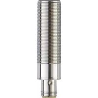
DTM426 - RFID system IFM - Free user manual and instructions
Find the device manual for free DTM426 IFM in PDF.


User questions about DTM426 IFM
0 question about this device. Answer the ones you know or ask your own.
Ask a new question about this device
Download the instructions for your RFID system in PDF format for free! Find your manual DTM426 - IFM and take your electronic device back in hand. On this page are published all the documents necessary for the use of your device. DTM426 by IFM.
USER MANUAL DTM426 IFM
Operating instructions
J1939 interface
RF-identification system
DTM426
DTM427
Read/write head
Contents
1 Preliminary note 3
1.1 Symbols used 3
1.2 Warnings.... 3
1.3 Legal and copyright information 3
1.4 Open source information.... 3
2 Safety instructions.... 4
2.1 Safety symbols on the unit 4
2.2 Safety note on high-frequency electromagnetic radiation 4
2.3 Cybersecurity 5
3 Intended use.... 6
3.1 Application area 6
4 Items supplied.... 7
5 Function 8
5.1 ID tags 8
5.2 Device overview 8
6 Installation.... 9
6.1 Notes on the unit installation 9
6.2 Avoiding interference 9
6.3 Mechanical design 9
6.4 Install device.... 10
6.5 Mounting distances.... 10
6.6 Positioning of the ID tags 11
7 Electrical connection.... 13
7.1 Wiring 13
8 Operating and display elements 14
9 Operation 15
9.1 J1939 interface 15
9.1.1 Proprietary protocol in PDU format 1.... 16
9.1.2 Configuration example 16
9.2 Parameter mapping.... 17
9.3 Device status 17
9.4 ID tag data access 19
9.4.1 Read data from ID tag.... 19
9.4.2 Write data to ID tag 19
9.5 Settings.... 20
9.5.1 Device address (0x2000) and baud rate (0x2001). 20
9.5.2 Address claiming.... 20
9.5.3 Reset read/write head 20
10 Maintenance, repair and disposal 21
11 Approvals/standards 22
Glossary 23
1 Preliminary note
You will find instructions, technical data, approvals and further information using the QR code on the unit / packaging or at documentation.ifm.com.
1.1 Symbols used
√ Requirement
Instructions
Reaction, result
[...] Designation of keys, buttons or indications
→ Cross-reference

Important note
Non-compliance may result in malfunction or interference.

Information
Supplementary note
1.2 Warnings
Warnings indicate the possibility of personal injury and damage to property. This enables safe product handling. Warnings are graded as follows:

WARNING
Warning of serious personal injury
▷ If the warning is not observed, fatal and serious injuries are possible.

CAUTION
Warning of minor to moderate personal injury
▷ If the warning is not observed, minor to moderate injuries are possible.
ATTENTION
Warning of damage to property
▷ If the warning is not observed, damage to property is possible.
1.3 Legal and copyright information
© All rights reserved by ifm electronic gmbh. No part of these instructions may be reproduced and used without the consent of ifm electronic gmbh.
All product names, pictures, companies or other brands used on our pages are the property of the respective rights owners.
1.4 Open source information

For more open source information see: documentation.ifm.com.
2 Safety instructions
- The unit described is a subcomponent for integration into a system.
- The system architect is responsible for the safety of the system.
-
The system architect undertakes to perform a risk assessment and to create documentation in accordance with legal and normative requirements to be provided to the operator and user of the system. This documentation must contain all necessary information and safety instructions for the operator, the user and, if applicable, for any service personnel authorised by the architect of the system.
-
Read this document before setting up the product and keep it during the entire service life.
- The product must be suitable for the corresponding applications and environmental conditions without any restrictions.
- Only use the product for its intended purpose (→ Intended use).
- If the operating instructions or the technical data are not adhered to, personal injury and/or damage to property may occur.
- The manufacturer assumes no liability or warranty for any consequences caused by tampering with the product or incorrect use by the operator.
- Installation, electrical connection, set-up, operation and maintenance of the product must be carried out by qualified personnel authorised by the machine operator.
- Protect units and cables against damage.
• Store the product in its original packaging.
2.1 Safety symbols on the unit
The following symbols are used on the device. Observe the instructions in order to avoid hazards:


• Electric supply must correspond to IEC 61010-1, chapter 9.4 - Limited-energy circuit.
• Device of protection class III. Only for operation in SELV/PELV circuits.
2.2 Safety note on high-frequency electromagnetic radiation
Under application-specific conditions, the risk for the user may differ depending on the installation situation and the device settings.
The system architect/operator is required to carry out a hazard analysis and to take appropriate measures for the protection of persons. In particular national regulations also have to be adhered to. Possible protective measures may include guaranteed minimum distances of a user, access controls and user training.

WARNING
Operation of this device can cause radio interference in residential areas.
▷ The device emits high-frequency electromagnetic waves that may interfere with the operation of electronic devices in the vicinity, including pacemakers, hearing aids and defibrillators.
▶ Due to human exposure regulations, a minimum distance of 20 cm must be maintained between the device and persons.
▶ If you have a pacemaker or other implanted medical product, do not use the device without first consulting your doctor or the manufacturer of your medical product. Keep a safe distance between the device and your medical devices and refrain from further use of the device if you observe permanent impairment of your medical product.
2.3 Cybersecurity
Installation
The device is suitable for operation in a secure environment according to IEC 62443-1-1.
The device was designed for operation behind a firewall.
▶ Carry out a risk assessment of the system according to IEC 62443-1-1.
▶ Take measures to ensure physical security.
Operation
▶ Observe the security functions described in the product documentation and the recommendations for their use.
Maintenance
▶ Regularly check whether software updates are available for the device.
- ▶ Back up system configuration and system data in accordance with your company's change management processes.
Decommissioning
▶ Ensure that no sensitive information can fall into unauthorised hands.
▶ Always reset the system settings to the factory settings before decommissioning the device.
3 Intended use
The read/write head reads and writes ID tags without contact.
The data is made available as process data via the CAN bus interface.
3.1 Application area
The device safety is rated for use under the following operating conditions:
- Protection class 3 (SELV/PELV) and supply of the device to limited energy according to IEC 61010-1, chapter 9.4. Isolate the external circuits as shown in figure 102 in IEC 61010-2-201.
- Indoor and outdoor use.
• Altitudes up to 2000 m. - Relative air humidity up to max. 80 %, non condensing.
- Pollution degree 2.
4 Items supplied
- Read/write head

The device is supplied without installation and connection accessories.
Available accessories: www.ifm.com.
The optimum function is not ensured when using components from other manufacturers.
5 Function
5.1 ID tags
The ID tags are passively operated without a battery. The energy required for operation is provided by the read/write head.
The energy is provided via an inductive coupling. The integrated antenna coil in the read/write head generates a magnetic field which partly penetrates the antenna coil of the ID tag. A voltage is generated by induction that supplies the data carrier with energy.
The device supports ID tags according to ISO 15693.
5.2 Device overview
DTM426
 | Article number: | DTM426 |
| Function: | Read/write head | |
| Type designation: | DTMHF GBRWCJUS03 | |
| Type: | M18, flush mountable |
DTM427
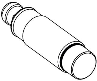 | Article number: | DTM427 |
| Function: | Read/write head | |
| Type designation: | DTMHF GNRWCJUS03 | |
| Type: | M18, non flush mountable |
6 Installation
6.1 Notes on the unit installation
When mounting several RFID units adhere to the minimum distances between the systems.
Flush mounting of a read/write head in metal reduces the read/write distance.
Device performance can be affected if positioned in the immediate vicinity of powerful HF emission sources such as welding transformers or converters.
6.2 Avoiding interference
The device generates a modulated electrical field with a frequency of 13.56 MHz.
Avoid interference with data communication:
▶ Do not operate any devices in the vicinity that use the same frequency band.
▷ Such devices are for example frequency converters and switched-mode power supplies.
If there are other devices in the same frequency band in the vicinity:
▶ The mounting distances between the devices should be as large as possible.
▶ Use the devices in alternating operation.
▶ Switch the HF field of the device on/off.
6.3 Mechanical design
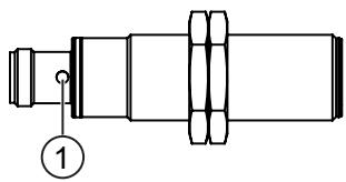
DTM426

Fig. 1: DTM426
1 Sensing face
DTM427

Fig. 2: DTM427
1 Sensing face
6.4 Install device
▶ Fix the device using the supplied nuts (M18).
DTM426

Fig. 3: Flush mounting
DTM427

Fig. 4: Non-flush mounting
6.5 Mounting distances
DTM426

| Operating mode | Distance side (A) | Distance front (B) |
| For reading and writing | ≥ 50 mm | ≥ 100 mm |
DTM427

| Operating mode | Distance side (A) | Distance front (B) |
| For reading and writing | ≥ 65 mm | ≥ 180 mm |
6.6 Positioning of the ID tags
The sensing face marks the centre of the integrated antenna coil of the read/write head.
▶ Align the sensing face of the read/write head and the ID tag in the same way.
For installation in or on metal use the ID tags provided for this purpose.
Position the ID tag in the area of the sensing face. When doing so, the angle of aperture and the operating distance must be adhered to (→ Data sheet of the device).
DTM426

Fig. 5: Position the ID tag
▶ Align the ID tag on the central axis of the antenna of the device.
The distance "D" is indicated in the data sheet.
DTM427

Fig. 6: Position the ID tag
▶ Align the ID tag on the central axis of the antenna of the device.
The distance "D" is indicated in the data sheet.
7 Electrical connection

The device must be connected by a qualified electrician.
Device of protection class III (PC III).
The electrical supply must only be made via PELV/SELV circuits.
▶ Disconnect power before connecting the device.
7.1 Wiring
▶ Connect the device to the CAN bus using the M12 connector.
▷ Voltage is supplied via the CAN bus.
| Pin assignment | Wiring |
| M12 connector, A-coded, 5 poles | |
| 1: Shield2: U+3: GND4: CAN high5: CAN low | |

The CAN bus connection is almost trouble-free if the following points are considered:
▶ Use cables approved for CAN bus.
▶ Terminate the cables with 120 Ω terminating resistors.

Information on available sockets see: www.ifm.com.
8 Operating and display elements
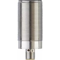
| DTM426 | DTM427 |
 |  |
1 LEDs green / yellow / red
| LED | State | Description |
| green | on | Operating status operational |
| flashes | Device deactivated | |
| yellow | on | ID tag detected |
| flashes once for 1/4 s | ID tag read or written successfully | |
| flashes briefly 4x | ID tag read or written with errors | |
| red | on | CAN bus not accessible |
| flashes | Device hardware fault |
9 Operation
9.1 J1939 interface
The RFID read/write heads have a standardised SAE J1939 interface. All measured values and parameters can be accessed via the J1939 protocol. The individual configuration can be saved in the internal permanent memory.
Structure of the SAE J1939 protocol
The SAE J1939 protocol uses a 29-bit CAN identifier (extended frame format CAN 2.0B). A J1939 message has the following structure:
| J1939 message | |||
| 29-bit CAN identifier | Data | ||
| Priority | Parameter Group Number (PGN) | Source address | User data of the message |
| 28...26 | 25...8 | 7...0 | 0...8 bytes |

| Parameter Group Number (PGN) | |||
| Ext. Data Page | Data Page | PDU Format (PF) | Target address / group extension (PS) |
| 25 | 24 | 23...16 | 15...8 |

| PDU format 1 (specific) | |
| 00h - EFh | Target Address (DA) |
| 23...16 | 15...8 |
| PDU format 2 (global) | |
| F0h - FFh | Group Extension (GE) |
| 23...16 | 15...8 |
PDU format 1
This format defines a message which is sent to a defined device. In this case the PDU-specific byte (PS) is the target address (DA) of the device. If the value of the PDU format field (PF) is between 0x00 and 0xEF, it is a PDU format 1 message.
For proprietary messages (manufacturer-specific) the PDU format value 0xEF is defined.
Ext. data page bit = 0 and data page bit = 0.
PDU format 2
This format defines a message which is sent globally. In this case the PDU specific byte (PS) corresponds to the group extension (GE). If the value of the PDU format field (PF) is between 0xF0 and 0xFF, it is a PDU format 2 message.
For proprietary messages (manufacturer-specific) the area PDU format (PF) and group extension (GE) 0xFF00 - 0xFFFF is defined.
Ext. data page bit = 0 and data page bit = 0.
9.1.1 Proprietary protocol in PDU format 1
The parameters of the device are listed in a table that is accessed per 16-bit index. To access the sensor parameters in reading or writing the proprietary PDU format 1 message is used. PDU format (PF) corresponds to the value 0xEF. In this case the PDU-specific byte (PS) is the target address (DA) of the device which is to receive the message. If more than 4 bytes are transferred, the J1939 transport protocol must be used.
Example
Address target device (ECU): 0x3B
Address control unit / master: 0x14
Priority of the message: 3
| CAN identifier | 8-byte data frame | |||
| ID | Parameter index | Read/Write | Status | 4-byte data |
| 29 bits | 2 bytes | 1 bytes | 1 bytes | |
Requirement: Master → ECU
| CAN identifier | 8-byte data frame | |||||||
| 0xFEFB14 | LSB | MSB | RW | 0 | LSB | .. | .. | MSB |
Response: Master ← ECU
| CAN identifier | 8-byte data frame | |||||||
| 0xCEF14EB | LSB | MSB | RW | SC | LSB | .. | .. | MSB |
Parameter index: 2-byte parameter index.
RW: Read parameter → 0x00 / write parameter → 0x01
SC: Status code
0x00: Ok
0x01: Parameter value too small
0x02: Parameter value too big
0x03: Parameter index does not exist
0x04: Parameter can only be read
0x05: Parameter can only be written
0x06: No access to parameter
0x07: Invalid data size
0x08: Parameter writing blocked
(Example: The value to be written is already set in the sensor)
0x09: Invalid command
0x0A: Unknown error
0x0B: Error while reading or writing from ID tag
9.1.2 Configuration example
Set block size of ID tag to 8, index 0x2800
Address target device (ECU): 0xEB
Address control unit / master: 0x14
Priority of the message: 3
Requirement: Master → ECU
| CAN identifier | 8-byte data frame | |||||||
| 0CEFEB14 | 0x00 | 0x28 | 0x01 | 0x00 | 0x08 | 0x00 | 0x00 | 0x00 |
Response: Master ← ECU
| CAN identifier | 8-byte data frame | |||||||
| 0xCEF14EB | 0x00 | 0x28 | 0x01 | 0x00 | 0x08 | 0x00 | 0x00 | 0x00 |
9.2 Parameter mapping
| Index | Type | Value | R/W | Saved | Preset |
| 0x0500 | Byte stream | Device Name | ro | ||
| 0x0501 | Byte stream | Software version | ro | ||
| 0x2000 | Unsigned8 | Default device address (may be changed after address claiming) | rw | X | 235 |
| 0x2001 | Unsigned16 | Baud rate in kbit/s | rw | X | 250 |
| 0x2002 | Boolean | Device reset | rw | ||
| 0x2080 | Unsigned8 | Device status | ro | ||
| 0x2800 | Unsigned8 | Block size | rw | X | 4 |
| 0xA000 | Byte stream | ID tag UID | ro | ||
| 0xA001 | Byte stream | ID tag data | rw |
9.3 Device status
The parameter with the index 0x2080 represents the current device status:
| Bit | 31 | 30 | 29 | 28 | 27 | 26 | 25 | 24 |
| Status | tag_err | |||||||
| Bit | 23 | 22 | 21 | 20 | 19 | 18 | 17 | 16 |
| Status | acc_err | |||||||
| Bit | 15 | 14 | 13 | 12 | 11 | 10 | 9 | 8 |
| Status | r | r | r | r | r | r | r | J1939_err |
| Bit | 7 | 6 | 5 | 4 | 3 | 2 | 1 | 0 |
| Status | claim | r | buf_ovfl | fr_err | r | present | ant | pow |
| Status | Value | Description |
| pow | 1 | Power enabled (value always 1) |
| ant | 0 | Antenna deactivated |
| 1 | Antenna activated | |
| present | 0 | No ID tag present |
| 1 | ID tag present | |
| fr_err | 0 | Front end OK |
| 1 | Front end error detected (hardware problem) | |
| buf_ovfl | 0 | Buffer OK |
| 1 | Buffer overflow detected | |
| claim | 0 | Address claiming OK |
| 1 | Address claiming not successful | |
| J1939_err | 0 | No J1939 error occurred |
| 1 | J1939 error occurred | |
| acc_err | Error of last write operation | |
| tag_err | 1 | Error message ID tag for last operation |
Access error codes
Updated after each write or read access of the ID tag.
| Index | Value | Description |
| 0x00 | ISO_COMMAND_ERROR_NO_ERROR | No error, command successfully executed. |
| 0x01 | ISO_COMMAND_ERROR_NO_RESPONSE | ID tag did not answer. Maybe ID tag is not in the field anymore. |
| 0x02 | ISO_COMMAND_ERROR_RX_ERROR | Error while receiving the answer from the ID tag (CRC error, framing error, collision, etc.). |
ID tag error codes
Updated after each read or write access of the ID tag.
| Index | Value | Description |
| 0x00 | ISO_TAG_ERROR_NO_ERROR | No error from the ID tag. |
| 0x01 | ISO_TAG_ERROR_COMMAND_NOT_SPECIFIED | The command is not supported. |
| 0x02 | ISO_TAG_ERROR_COMMAND_SYN-TAX | Cannot recognise the command. The number of blocks is too high. Example: format error. |
| 0x03 | ISO_TAG_ERROR_OPTION_NOT_SUPPORTED | Option is not supported. |
| 0x0F | ISO_TAG_ERROR_OTHER | Other error. |
| 0x10 | ISO_TAG_ERROR_BLOCK_NOT_USA-BLE | The specified block cannot be used (or was not found). |
| 0x11 | ISO_TAG_ERROR_BLOCK_AL-READY_BLOCKED | The specified block is locked and cannot be locked again. |
| 0x12 | ISO_TAG_ERROR_BLOCK_NOT_UP-DATEABLE | The specified block is locked and its contents cannot be up-dated. |
| 0x13 | ISO_TAG_ER-ROR_BLOCK_WRITE_VERIFY | The specified block cannot be programmed (a write verify er-ror occurred). |
| 0x14 | ISO_TAG_ER-ROR_BLOCK_LOCK_VERIFY | The specified block cannot be locked (a lock verify error oc-curred). |
9.4 ID tag data access
9.4.1 Read data from ID tag
The data is read by the ID tag by sending a "read parameter" frame with the following information:
- Data address
- Data length
| CAN identifier | 8-byte data frame | |||||||
| ID29 bits | Parameter index2 bytes | Read/Write1 byte | Status1 byte | ID tagData address | ID tagData length | |||
| 0x01 | 0xA0 | 0x00 | 0x00 | LSB | MSB | LSB | MSB | |
Example
Read 8 bytes of data from ID tag address 4.
Requirement: Master → ECU
| CAN identifier | 8-byte data frame | |||||||
| 0CEFEB14 | 0x01 | 0xA0 | 0x00 | 0x00 | 0x04 | 0x00 | 0x08 | 0x00 |
Response: Master ← ECU
| CAN identifier | 8-byte data frame | |||||||
| 0xCEF14EB | 0x01 | 0xA0 | 0x00 | 0x00 | Data[0] | Data[1] | Data[2] | ... |
For successful reading and writing, the ID tag must be in the detection range of the read/write head. In the event of data read and write errors, the status byte responds with 0x0B.
9.4.2 Write data to ID tag
The data is written to the ID tag by sending a "write parameter" frame with the following information:
- Data address
- Data length
- Data
| CAN identifier | x-byte data frame | |||||||||
| ID29 bits | Parameter index2 bytes | Read/Write1 byte | Status1 byte | ID tagData address | ID tagData length | ID tagData | ||||
| 0x01 | 0xA0 | 0x00 | 0x00 | LSB | MSB | LSB | MSB | Data[0] | Data[x] | |
Example
Write 4 bytes of data (0xAA,0xBB,0xCC,0xDD) to ID tag address 2.
Requirement: Master → ECU
| CAN identifier | x-byte data frame | |||||||||||
| 0xCEF EB14 | 0x01 | 0xA0 | 0x01 | 0x00 | 0x02 | 0x00 | 0x04 | 0x00 | 0xAA | 0xBB | 0xCC | 0xDD |
Response: Master ← ECU
| CAN identifier | x-byte data frame | |||
| 0xCEF14EB | 0x01 | 0xA0 | 0x01 | 0x00 |

For successful reading and writing, the ID tag must be in the detection range of the read/write head. In the event of data read and write errors, the status byte responds with 0x0B.
9.5 Settings
9.5.1 Device address (0x2000) and baud rate (0x2001)
Valid values for the device address are: 0 to 253.
Preferably use the preset device address. Via "address claiming" the device address can be changed. Valid values for the baud rate are: 250 kBits/s, 500 kBits/s.

Default settings of the device:
▷ Device address (ECU): 235
▷ Baud rate: 250 kBits/s

Use the set device address only once in the CAN network.
▶ Use “address claiming” in the CAN network to avoid conflicts. (→ Address claiming ☐ 20)

Only after resetting the read/write head will a changed device address and baud rate become effective.
▶ Reset the read/write head with the reset command or hardware reset. (→ Reset read/write head ☐ 20)
9.5.2 Address claiming
The read/write head supports "dynamic address claiming".
By default, the device address is 235. With the device address, the sensor logs in to the network during start-up. Unless there is an address conflict with other network participants, the sensor starts communication automatically.
Arbitrary address capable (CA)
If the set address of the device is already used in the network, the participant with a higher priority will be accepted by the network. The rejected network participant with a lower priority will be assigned another valid device address.
9.5.3 Reset read/write head
By writing the value "1" to the parameter index 0x2002 the read/write head is reset.

After writing the value, the read/write head is reset immediately. No response frame is sent from the read/write head.
10 Maintenance, repair and disposal
The unit is maintenance-free.
▶ Contact ifm in case of malfunction.
▶ Do not open the housing as the unit does not contain any components which can be maintained by the user. The unit must only be repaired by the manufacturer.
▶ Clean the device using a dry cloth.
▶ Dispose of the unit in accordance with the national environmental regulations.
11 Approvals/standards
For approvals and standards, the following information is available:
• Test standards and regulations: documentation.ifm.com
• EU declaration of conformity and approvals: documentation.ifm.com
• Notes relevant for approval: Package insert of the device and documentation.ifm.com
Glossary
CAN
Controller Area Network, bus system for use in mobile applications.
ID tag
An ID tag is used to identify objects. A read/write device is used to read the ID tag via a high-frequency radio signal. An ID tag consists of an antenna, an analogue circuit for receiving and transmitting (transceiver), a digital circuit and a non-volatile memory.
- 1 PRELIMINARY NOTE
- 1.1 SYMBOLS USED
- 1.2 WARNINGS
- 1.3 LEGAL AND COPYRIGHT INFORMATION
- 1.4 OPEN SOURCE INFORMATION
- 2 SAFETY INSTRUCTIONS
- 2.1 SAFETY SYMBOLS ON THE UNIT
- 2.2 SAFETY NOTE ON HIGH-FREQUENCY ELECTROMAGNETIC RADIATION
- 2.3 CYBERSECURITY
- 3 INTENDED USE
- 3.1 APPLICATION AREA
- 4 ITEMS SUPPLIED
- 5 FUNCTION
- 5.1 ID TAGS
- 5.2 DEVICE OVERVIEW
- 6 INSTALLATION
- 6.1 NOTES ON THE UNIT INSTALLATION
- 6.2 AVOIDING INTERFERENCE
- 6.3 MECHANICAL DESIGN
- 6.4 INSTALL DEVICE
- 6.5 MOUNTING DISTANCES
- 6.6 POSITIONING OF THE ID TAGS
- 7 ELECTRICAL CONNECTION
- 7.1 WIRING
- 8 OPERATING AND DISPLAY ELEMENTS
- 9 OPERATION
- 9.1 J1939 INTERFACE
- 9.1.1 PROPRIETARY PROTOCOL IN PDU FORMAT 1
- 9.1.2 CONFIGURATION EXAMPLE
- 9.2 PARAMETER MAPPING
- 9.3 DEVICE STATUS
- 9.4 ID TAG DATA ACCESS
- 9.4.1 READ DATA FROM ID TAG
- 9.4.2 WRITE DATA TO ID TAG
- 9.5 SETTINGS
- 9.5.1 DEVICE ADDRESS (0X2000) AND BAUD RATE (0X2001)
- 9.5.2 ADDRESS CLAIMING
- 9.5.3 RESET READ/WRITE HEAD
- 10 MAINTENANCE, REPAIR AND DISPOSAL
- 11 APPROVALS/STANDARDS
Brand : IFM
Model : DTM426
Category : RFID system