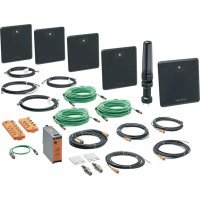
ZZ0817 - RFID system IFM - Free user manual and instructions
Find the device manual for free ZZ0817 IFM in PDF.


User questions about ZZ0817 IFM
0 question about this device. Answer the ones you know or ask your own.
Ask a new question about this device
Download the instructions for your RFID system in PDF format for free! Find your manual ZZ0817 - IFM and take your electronic device back in hand. On this page are published all the documents necessary for the use of your device. ZZ0817 by IFM.
USER MANUAL ZZ0817 IFM
Instructions for set-up
RF-identification system
ZZ0814
ZZ0815
ZZ0816
ZZ0817
Incoming/outgoing goods
Contents
1 Preliminary note 3
1.1 Symbols used 3
1.2 Warnings.... 3
1.3 Legal and copyright information 3
2 Safety instructions.... 4
2.1 Safety instructions for loading/unloading 4
3 Intended use.... 5
4 Items supplied.... 6
5 Function 8
5.1 Load control 9
5.2 Logging....9
5.3 Loading Unloading 10
6 Installation.... 11
6.1 Installing set ZZ0814.... 11
6.2 Installing set ZZ0816.... 12
6.3 Installing sets next to each other with divider grid 13
7 Electrical connection.... 14
7.1 Connecting the ZZ0814 15
7.2 Connecting the ZZ0815 15
7.3 Connecting the ZZ0816 16
7.4 Connecting the ZZ0817.... 16
7.5 ZZ1124 pin assignment.... 17
7.6 DTE830 pin assignment 18
7.7 Wiring AL1326 20
7.8 AL3050 pin assignment.... 22
7.9 O3D354 pin assignment 23
8 Set-up 24
8.1 DTE830....24
8.2 O3D354 24
8.2.1 Connecting ifm Vision Assistant 24
8.2.2 Creating an application 24
8.3 ZZ1124 25
8.3.1 Data exchange between ZZ1124 and higher-level system 25
8.3.1.1 File exchange with result file 27
8.3.1.2 File exchange without result file 28
8.3.2 Structure of the feedback file.... 28
8.3.2.1 Examples 29
8.3.3 Structure of the results file.... 29
8.3.3.1 Examples 30
8.3.4 Retrieving the feedback file via SSH 31
8.3.5 MQTT 32
8.4 DV2510.... 34
9 Maintenance, repair and disposal 36
10 Approvals/standards 37
Glossary 38
1 Preliminary note
You will find instructions, technical data, approvals and further information using the QR code on the unit / packaging or at www.ifm.com.
1.1 Symbols used
√ Requirement
Instructions
Reaction, result
[...] Designation of keys, buttons or indications
→ Cross-reference

Important note
Non-compliance may result in malfunction or interference.

Information
Supplementary note
1.2 Warnings
Warnings indicate the possibility of personal injury and damage to property. This enables safe product handling. Warnings are graded as follows:

WARNING
Warning of serious personal injury
▷ If the warning is not observed, fatal and serious injuries are possible.

CAUTION
Warning of minor to moderate personal injury
▷ If the warning is not observed, minor to moderate injuries are possible.
ATTENTION
Warning of damage to property
▷ If the warning is not observed, damage to property is possible.
1.3 Legal and copyright information
© All rights reserved by ifm electronic gmbh. No part of these instructions may be reproduced and used without the consent of ifm electronic gmbh.
All product names, pictures, companies or other brands used are the property of the respective rights owners.
2 Safety instructions
- The unit described is a subcomponent for integration into a system.
- The system architect is responsible for the safety of the system.
-
The system architect undertakes to perform a risk assessment and to create documentation in accordance with legal and normative requirements to be provided to the operator and user of the system. This documentation must contain all necessary information and safety instructions for the operator, the user and, if applicable, for any service personnel authorised by the architect of the system.
-
Read this document before setting up the product and keep it during the entire service life.
- The product must be suitable for the corresponding applications and environmental conditions without any restrictions.
- Only use the product for its intended purpose (→ Intended use).
- If the operating instructions or the technical data are not adhered to, personal injury and/or damage to property may occur.
- The manufacturer assumes no liability or warranty for any consequences caused by tampering with the product or incorrect use by the operator.
- Installation, electrical connection, set-up, operation and maintenance of the product must be carried out by qualified personnel authorised by the machine operator.
- Protect units and cables against damage.
2.1 Safety instructions for loading/unloading

WARNING
Severe injuries and bruises
▷ The ZZ081x set does not replace the proper loading and unloading of goods.
▷ Goods that are not loaded and unloaded properly can fall and injure people in the vicinity.
▶ Load and unload incoming and outgoing goods properly and safely.
3 Intended use
The ZZ081x set is a system to detect incoming and outgoing goods in outdoor and indoor areas. The incoming and outgoing goods are equipped with ID tags and are recorded by RFID read/write heads.
Data such as the loading direction and the time stamp are recorded via the ID tags.
If the gate function Load control is activated, the data is provided and the system waits for a response from the ERP system.
If the gate function Logging is activated, the data is provided as a feedback file. The feedback file is retrieved from an ERP system or MQTT broker. The ERP system or the MQTT broker must be provided by the operator.
The ERP system saves successful unloading and loading in a result file. The result file is sent to the edge
Controller. The edge
Controller analyses the unloading and loading of goods via the results file. The result can then be signalled via the connected signal light and the buzzer.
Clients connected to the MQTT broker can retrieve and process the data.
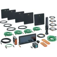
The set ZZ081x includes all devices and cables necessary for operation. The ID tags are not included.
The devices are pre-programmed. The O3
Dxxx device must be set up for the application using the ifm Vision Assistant software. The ZZ081x set can then be put into operation after assembly and electrical connection.
4 Items supplied
The ZZ081x sets are divided into gates and detection of the loading direction.
• Master gate: ZZ0814, ZZ0816
• Extension gate: ZZ0815, ZZ0817

Up to 9 extension gates can be operated on one master gate.
The loading direction of the goods is detected differently by the sets:
• Detection via O3D 3D sensor: ZZ0814, ZZ0815
• Detection via 2x light barrier: ZZ0816, ZZ0817

The device is supplied without installation and connection accessories.
Available accessories: www.ifm.com.
The optimum function is not ensured when using components from other manufacturers.
Scope of delivery ZZ0814, ZZ0815 (detect loading direction via O3D 3D sensor)
| Article | ZZ0814 master gate | ZZ0815 extension gate | Description |
| ZZ1124 | 1 | 0 | edge Controller with gate soft-ware |
| E70450 | 1 | 0 | Connection cable for ZZ1124 |
| DTE830 | 1 | 1 | RFID evaluation unit UHF |
| ANT860 | 4 | 4 | RFID antenna UHF |
| E80332 | 4 | 1 | Connection cable |
| AL3050 | 1 | 1 | Ethernet switch (M12) |
| AL1326 | 1 | 1 | IO-Link master with Ether Net/IP interface |
| O3D354 | 1 | 1 | 3D sensor |
| DV2510 | 1 | 1 | 5-segment light tower |
| EVC108 | 1 | 1 | Connection cable |
| DN4032 | 1 | 1 | Switched-mode power supply 24 V DC |
| EVC003 | 4 | 4 | Connection cable with socket |
| E12166 | 1 | 1 | Connection cable with socket for O3D |
| EVC928 | 1 | 0 | Ethernet connection cable with RJ45 plug |
| EVC907 | 1 | 1 | Ethernet connection cable, 5 m |
| EVC908 | 3 | 3 | Ethernet connection cable, 10 m |
| E80412 | 1 | 1 | Adapter cable for DTE830 |
Scope of delivery ZZ0816, ZZ0817 (detect loading direction via 2x light barrier)
| Article | ZZ0816 master gate | ZZ0817 extension gate | Description |
| ZZ1124 | 1 | 0 | edge Controller with gate soft-ware |
| E70450 | 1 | 0 | Connection cable for ZZ1124 |
| DTE830 | 1 | 1 | RFID evaluation unit UHF |
| ANT860 | 4 | 4 | RFID antenna UHF |
| E80332 | 4 | 1 | Connection cable |
| AL3050 | 1 | 1 | Ethernet switch (M12) |
| AL1326 | 1 | 1 | IO-Link master with Ether Net/IP interface |
| OGP700 | 2 | 2 | Laser retro-reflective sensor |
| E20722 | 2 | 2 | Reflector for retro-reflective laser sensor |
| DV2510 | 1 | 1 | 5-segment light tower |
| EVC108 | 3 | 3 | Connection cable |
| DN4032 | 1 | 1 | Switched-mode power supply 24 V DC |
| EVC003 | 4 | 4 | Connection cable with socket |
| EVC928 | 1 | 0 | Ethernet connection cable with RJ45 plug |
| EVC907 | 1 | 1 | Ethernet connection cable, 5 m |
| EVC908 | 3 | 3 | Ethernet connection cable, 10 m |
| E80412 | 1 | 1 | Adapter cable for DTE830 |
5 Function
The ZZ081x set is a system to detect incoming and outgoing goods in outdoor and indoor areas. The incoming and outgoing goods are equipped with ID tags and are recorded by RFID read/write heads.

The ID tags must be designed for the UHF band (ISO 18000-6C EPC Class1 Gen2).
The UHF devices included in the ZZ081x set are connected to the edge
Controller via TCP/IP. The data is processed in the edge
Controller.
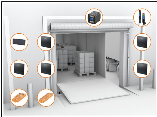
Contents of set ZZ0814:
O3D354 3D sensor
edge
Controller ZZ1124
RFID evaluation unit DTE830
RFID antenna ANT860
Ethernet switch AL3050
AL1122 IO-Link master
Signal light DV2510

Contents of set ZZ0816:
Retro-reflective laser sensor OGP700
edge
Controller ZZ1124
RFID evaluation unit DTE830
RFID antennas ANT860
Ethernet switch AL3050
AL1122 IO-Link master
Signal light DV2510
Functions
The ZZ0814 and ZZ0816 sets have the following functions:
- TCP/IP communication with up to 10 DTE830 UHF evaluation units (1x Master Gate and 9x Extension Gate)
- Set ZZ0814: Detection of the loading direction of the goods via O3D354 3D sensor
- Set ZZ0816: Detect the loading direction of the goods via the OGP700 retro-reflective laser sensor
- Creating a feedback file via the edge
Controller - Reading a result file via the edge
Controller
• Show status on the display of the edge
Controller and the light tower / buzzer - Simple user interface for evaluation unit configuration
- Gate function [Load control:] Providing the data and waiting for a response from the ERP system (→ Load control ☐ 9)
- Gate function [Logging]: Providing the data as a feedback file (→ Logging ☐ 9)
- Gate function [Loading Unloading]: Behaviour of the gate when detecting movements (→ Loading Unloading ☐ 10)
Functions not included
The following functions must be provided by the client:
- A program that collects the feedback file from the edge
Controller ZZ1124, sends it to the ERP system and then deletes it from the edge
Controller
• Evaluation in the ERP system
- Creation of a results file by the ERP system with pass/fail information
• A program for transferring the results file from the ERP system to the edge
Controller ZZ1124
• Mounting accessories for the devices
5.1 Load control
With activated gate function [Load control]:
• The data is provided.
- The system waits for a response from the higher-level ERP system. The response is sent as a result file from the connector program.

▶ Use the [File exchange] transfer method for the [Load control] gate function.
The [File exchange] transfer method requires a file exchange system.
The file exchange system is provided by the operator. The file exchange system retrieves the feedback file and forwards it to the higher-level ERP system. The feedback file contains the data from the last reading in JSON data format.
The higher-level ERP system compares the feedback file with the delivery note. The result of the comparison is written to the ERP results file. The ERP results file is sent back to the edge
Controller for evaluation. The edge
Controller uses the ERP results file to analyse the loading and unloading of goods.
5.2 Logging
If the gate function [Logging] is activated:
- The data from the readings is provided as a feedback file. As soon as >10 feedback files are available in the file system, the oldest one will be overwritten (ring buffer). Separate feedback files are provided for each gate.
- The system waits not for a response from the higher-level system.

▶ For the gate function [Logging], use the transmission method [File exchange] or [MQTT].
The [MQTT] transmission method requires a connected MQTT broker.
The MQTT broker is provided by the operator. The data read from the RFID incoming and outgoing goods recording system is sent from the edge
Controller to the MQTT broker. Clients connected to the MQTT broker then retrieve the data and process it further.
5.3 Loading Unloading
The [Loading Unloading] function sets the behaviour of the gate when movements are detected. Available settings:
| [Loading]: Book goods when moving towards the lorry. | [Unloading]: Book goods when moving from the direction of the lorry. | [Loading + Unloading]: Book goods when moving from and to the lorry. |
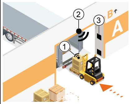 | 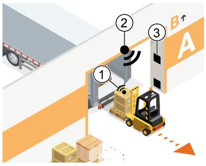 | 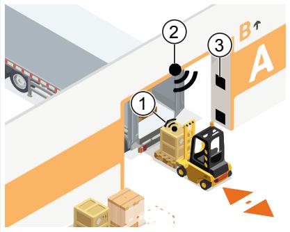 |
1: ID tag
2: Detection of direction
3: Antenna array
Loading
With the setting [Loading], goods are booked when moving towards the lorry. A movement in the opposite direction can be booked manually.
Depending on the orientation of the ID tag and in the case of a lorry trailer with fixed side walls (e.g. box body construction), the goods can be booked out automatically.
▶ Select the [Loading] setting for loading.
▶ Only allow goods to be booked out via manual confirmation.
▶ With direction detection via 3D sensor or laser reflex light barrier, only activate the antenna field when loading.
Unloading
With the setting [Unloading], goods are booked for a movement from the direction of the lorry. A movement in the opposite direction can be booked manually.
Depending on the orientation of the ID tag and in the case of a lorry trailer with fixed side walls (e.g. box body construction), the goods can book themselves in automatically.
▶ Select the [Unloading] setting for unloading.
▶ Only allow goods to be booked in via manual confirmation.
▶ With direction detection via 3D sensor or retro-reflective laser sensor, only activate the antenna array when unloading.
Loading + Unloading
With the setting [Loading + Unloading], goods are booked when moving from and to the lorry.
6 Installation
6.1 Installing set ZZ0814
The ZZ0814 set detects the loading direction via the O3D354 3D sensor.

1: edge
Controller ZZ1124
2: Direction detection with O3D354 3D sensor
3: Signal light DV2510
4: Upper RFID antennas ANT860
5: Lower RFID antennas ANT860
6: Distance between loading area and UHF gate
7: Distance between load and UHF gate
Fig. 1: Installed set ZZ0814
Install the devices in the set:
▶ Install the two lower ANT860 RFID antennas at a height of approx. 1 m (5).
▶ Install the upper two ANT860 RFID antennas at a height of approx. 2 m (4).
▷ A distance of at least 1 metre must be maintained between the loading area and the RFID antennas (6).
▷ A distance of at least 2.5 metres must be maintained between the load in the warehouse and the RFID antennas (7). If goods fitted with ID tags are stored too close to the RFID antennas, this can lead to errors being detected.
▶ Mount the DV2510 signal light so that it is clearly visible above the door (3).
▶ Mount the 3D sensor O3D354 in the centre above the door (2).
▷ The 3D sensor must be installed at a height of at least 2.50 metres. The exact height and position depends on the required detection range (ROI).
| Mounted height of the O3D354 | Detection zone |
| 2.50 m | 2.75 x 2.00 m |
| 3.00 m | 3.30 x 2.40 m |
| 3.50 m | 3.85 x 2.80 m |
| 4.00 m | 4.40 x 3.20 m |
▶ Install the edge
Controller ZZ1124 near the door (1).
▷ The set is installed.
6.2 Installing set ZZ0816
The ZZ0816 set detects the loading direction via the 2 OGP700 light barriers.

Fig. 2: Installed set ZZ0816
1: edge
Controller ZZ1124
2: Signal light DV2510
3: Upper RFID antennas ANT860
4: Lower RFID antennas ANT860
5: Direction detection with 2x OGP700 retro-reflective laser sensor
6: Distance between loading area and UHF gate
7: 2x reflector for retro-reflective laser sensor E20722
8: Distance between load and UHF gate
Install the devices in the set:
▶ Install the two lower ANT860 RFID antennas at a height of approx. 1 m (4).
▶ Install the upper two ANT860 RFID antennas at a height of approx. 2 m (3).
▷ A distance of at least 1 metre must be maintained between the loading area and the RFID antennas (6).
▷ A distance of at least 2.5 metres must be maintained between the load in the warehouse and the RFID antennas (8). If goods fitted with ID tags are stored too close to the RFID antennas, this can lead to errors being detected.
▶ Mount the DV2510 signal light so that it is clearly visible above the door (2).
▶ Install the OGP700 retro-reflective laser sensors (5) and the E20722 reflectors (7) at a height of approx. 0.5 m.
▷ Maintain a distance of 0.3 m between the light barriers.
▶ Install the edge
Controller ZZ1124 near the door (1).
▷ The set is installed.
6.3 Installing sets next to each other with divider grid
Several sets can be installed next to each other by installing dividers between the sets. The divider grids prevent interference between the sets.
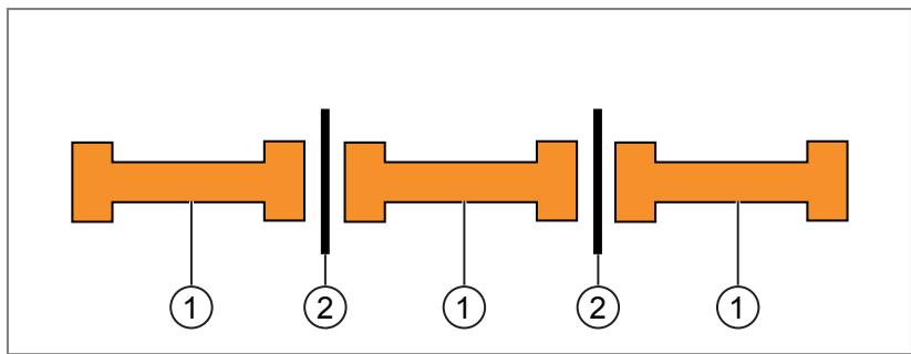
1: Set
2: Divider grid
Fig. 3: Sets mounted side by side with divider grid (bird's eye view)

Goods stored in the vicinity of the set can cause malfunctions.
▶ Do not store any goods within a radius of 2 metres.

The distances mentioned are rough guidelines and depend on the local installation situation and the settings used for the devices.
Install divider grids between the sets
Divider grids reduce the necessary distance between the sets.
Fit the divider grid between the sets:
▶ Keep a distance of 1 metre between the sets.
▶ Install a partition grid with minimum dimensions of 2.5 m x 2.0 m (height x width) between the sets.
Installing sets without divider grids
Without a divider grid between the sets, the distance required to avoid interference is greater.
Installing sets next to each other without divider grid:
▶ Keep a distance of 4 metres between the sets.
7 Electrical connection

The device must be connected by a qualified electrician.
Device of protection class III (PC III).
The electrical supply must only be made via PELV/SELV circuits.
▶ Disconnect power before connecting the device.
ATTENTION
The IP rating indicated in the data sheet is only reached if the M12 connectors are firmly screwed. Loosely screwed M12 connectors can damage the unit.
▶ Screw the M12 connector to the device applying 1 to 1.5 Nm.
▶ Cover unused device connections with protective covers.

Fig. 4: Connected devices
1: 24 V DV power supply (blue lines)
3: Ethernet (green lines)
5: Connection to the customer network (red line)
2: IO-Link (orange lines)
4: Coaxial connection (black lines)
Connect external PLC
Ports X01 and X02 of the AL1326 are used as standard for the OGP700 retro-reflective laser sensors. Alternatively, the ports can be used as digital inputs for an external PLC.
Further information on the digital inputs can be found in the AL1326 operating instructions: documentation.ifm.com
7.1 Connecting the ZZ0814
The Master Gate ZZ0814 detects the loading direction via the 3D sensor O3D354.
▶ Connect the devices as shown in the table.
| Starting the connection (device connection) | Connection via cable | Destination of the connection (device connection) |
| ZZ1124 - ETH0 | EVC908 | AL3050 - P1 |
| ZZ1124 – ETH 1 | EVC928 | Customer network |
| ZZ1124 - Supply | E70450 and EVC003 | DN4032 (24 V DC 5 A) |
| AL3050 - Supply | EVC003 | DN4032 (24 V DC 5 A) |
| DTE830 - PWR | EVC003 | DN4032 (24 V DC 5 A) |
| DTE830 - ETH | EVC907 and E80412 | AL3050 - P2 |
| DTE830 – AP 1 | E80332 | ANT860 (antenna 1) |
| DTE830 – AP 2 | E80332 | ANT860 (antenna 2) |
| DTE830 – AP 3 | E80332 | ANT860 (antenna 3) |
| DTE830 – AP 4 | E80332 | ANT860 (antenna 4) |
| AL1326 - PWR | EVC003 | DN4032 (24 V DC 5 A) |
| AL1326 – ETH0 | EVC908 | AL3050 - P3 |
| AL1326 – P3 | EVC108 | DV2510 |
| O3D - PWR | E12166 | DN4032 (24 V DC 5 A) |
| O3D – ETH | EVC908 | AL3050 - P4 |
7.2 Connecting the ZZ0815
The Extension Gate ZZ0815 is an extension for the master gate ZZ0814.
▶ Connect the devices as shown in the table.
| Starting the connection (device connection) | Connection via cable | Destination of the connection (device connection) |
| AL3050 – X31 | EVC003 | DN4032 (24 V DC 5 A) |
| AL3050 - P1 | EVC908 | ZZ0814 - free port of the AL3050 |
| DTE830 - PWR | EVC003 | DN4032 (24 V DC 5 A) |
| DTE830 - ETH | EVC907 and E80412 | AL3050 - P2 |
| DTE830 – AP 1 | E80332 | ANT860 (antenna 1) |
| DTE830 – AP 2 | E80332 | ANT860 (antenna 2) |
| DTE830 – AP 3 | E80332 | ANT860 (antenna 3) |
| DTE830 – AP 4 | E80332 | ANT860 (antenna 4) |
| AL1326 - PWR | EVC003 | DN4032 (24 V DC 5 A) |
| AL1326 – ETH0 | EVC908 | AL3050 - P3 |
| AL1326 – P3 | EVC108 | DV2510 |
| O3D - PWR | E12166 | DN4032 (24 V DC 5 A) |
| O3D – ETH | EVC908 | AL3050 - P4 |
7.3 Connecting the ZZ0816
The master gate ZZ0816 detects the loading direction via the OGP700 light barriers.
▶ Connect the devices as shown in the table.
| Starting the connection (device connection) | Connection via cable | Destination of the connection (device connection) |
| ZZ1124 - ETH0 | EVC908 | AL3050 - P1 |
| ZZ1124 – ETH 1 | EVC928 | Customer network |
| ZZ1124 - Supply | E70450 and EVC003 | DN4032 (24 V DC 5 A) |
| AL3050 - Supply | EVC003 | DN4032 (24 V DC 5 A) |
| DTE830 - PWR | EVC003 | DN4032 (24 V DC 5 A) |
| DTE830 - ETH | EVC907 and E80412 | AL3050 - P2 |
| DTE830 – AP 1 | E80332 | ANT860 (antenna 1) |
| DTE830 – AP 2 | E80332 | ANT860 (antenna 2) |
| DTE830 – AP 3 | E80332 | ANT860 (antenna 3) |
| DTE830 – AP 4 | E80332 | ANT860 (antenna 4) |
| AL1326 - PWR | EVC003 | DN4032 (24 V DC 5 A) |
| AL1326 – ETH0 | EVC908 | AL3050 - P3 |
| AL1326 – P3 | EVC108 | DV2510 |
| AL1326 – P1 | EVC108 | OGP700 |
| AL1326 – P2 | EVC108 | OGP700 |
7.4 Connecting the ZZ0817
The extension gate ZZ0817 is an extension for the master gate ZZ0816.
▶ Connect the devices as shown in the table.
| Starting the connection (device connection) | Connection via cable | Destination of the connection (device connection) |
| AL3050 – X31 | EVC003 | DN4032 (24 V DC 5 A) |
| AL3050 - P1 | EVC908 | ZZ0816 - free port of the AL3050 |
| DTE830 - PWR | EVC003 | DN4032 (24 V DC 5 A) |
| DTE830 - ETH | EVC907 and E80412 | AL3050 - P2 |
| DTE830 – AP 1 | E80332 | ANT860 (antenna 1) |
| DTE830 – AP 2 | E80332 | ANT860 (antenna 2) |
| DTE830 – AP 3 | E80332 | ANT860 (antenna 3) |
| DTE830 – AP 4 | E80332 | ANT860 (antenna 4) |
| AL1326 - PWR | EVC003 | DN4032 (24 V DC 5 A) |
| AL1326 – ETH0 | EVC908 | AL3050 - P3 |
| AL1326 – P3 | EVC108 | DV2510 |
| AL1326 – P1 | EVC108 | OGP700 |
| AL1326 – P2 | EVC108 | OGP700 |
7.5 ZZ1124 pin assignment
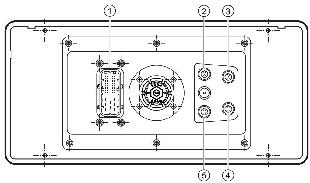
Fig. 5: ZZ1124 rear
1: Voltage supply
3: USB 1
5: Ethernet 1
2: USB 0
4: Ethernet 0
Voltage supply
| Pin assignment | Pin | Assignment |
 | 114 | L+ |
| 119 | L+ | |
| 120 | GND | |
| 121 | L+ |
Ethernet
| Pin assignment | Pin | Assignment |
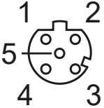 | 1 | TxD+ |
| 2 | RxD+ | |
| 3 | TxD- | |
| 4 | RxD- |
7.6 DTE830 pin assignment
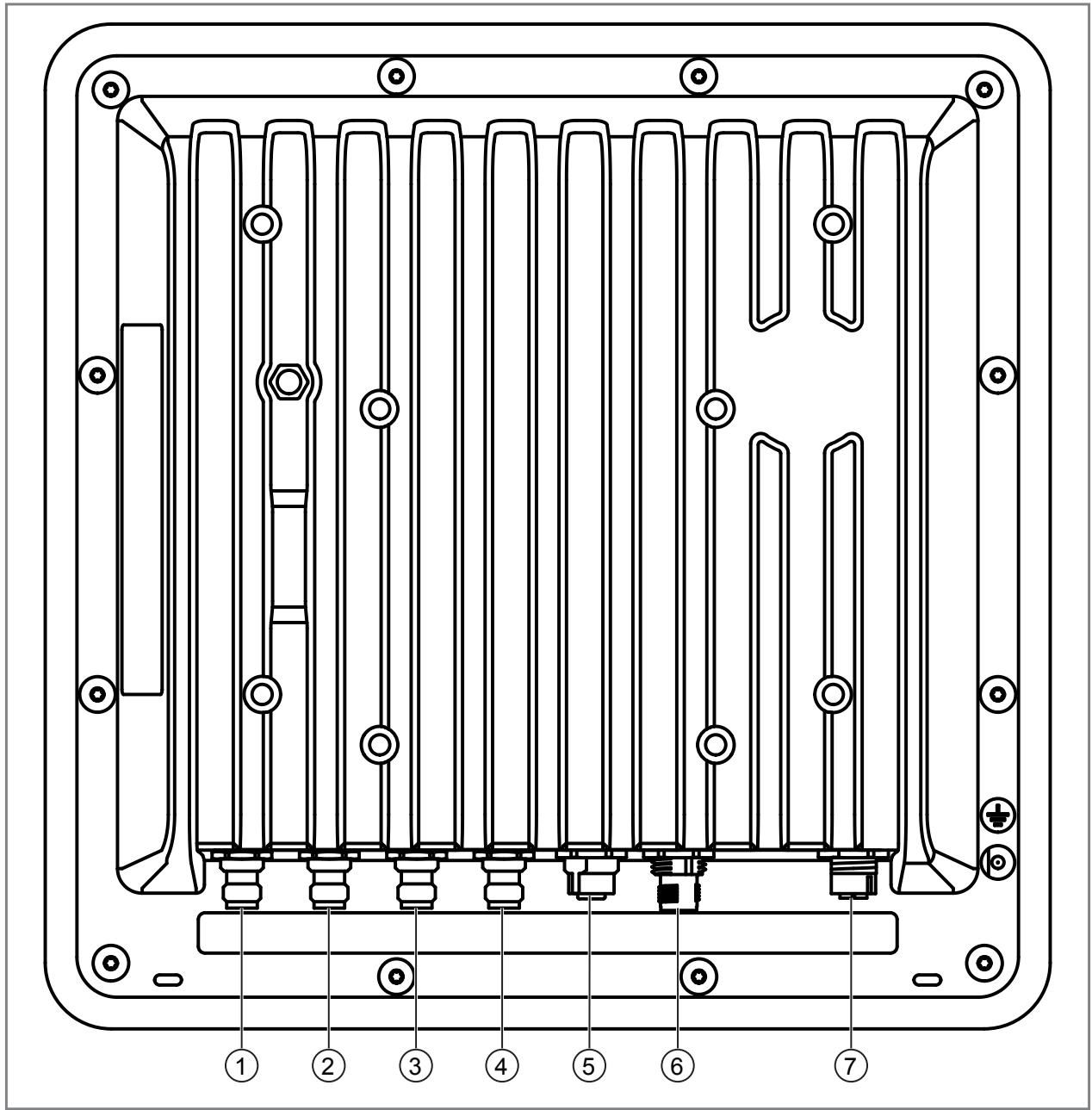
Fig. 6: DTE830 rear
1: Antenna 4, R-TNC 50 Ω
3: Antenna 2, R-TNC 50 Ω
5: GPIO, M12 socket, 12 poles, A-coded
7: Ethernet with PoE Plus (Power over Ethernet), M12 socket, 8 poles, X-coded
2: Antenna 3, R-TNC 50 Ω
4: Antenna 1, R-TNC 50 Ω
6: voltage supply, M12 connector, 4 poles, A-coded
GPIO
| Pin assignment | Pin | Assignment |
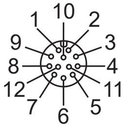 | 1 | OUT CMN |
| 2 | OUTPUT 1 | |
| 3 | INPUT 3 | |
| 4 | INPUT CMN | |
| 5 | INPUT 1 | |
| 6 | GND | |
| 7 | UB | |
 | 8 | OUTPUT 4 |
| 9 | OUTPUT 3 | |
| 10 | OUTPUT 2 | |
| 11 | INPUT 2 | |
| 12 | INPUT 4 |
Voltage supply
| Pin assignment | Pin | Assignment | |
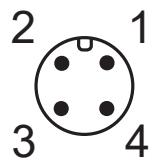 | 1 | +24 V DC | |
| 2 | GND | ||
| 3 | GND | ||
| 4 | +24 V DC | ||
Ethernet
| Pin assignment | Pin | Assignment |
 | 1 | TX+ / PoE+1 |
| 2 | TX- / PoE+1 | |
| 3 | TX+ / PoE+2 | |
| 4 | TX- / PoE+2 | |
| 5 | PoE+1 | |
| 6 | PoE+1 | |
| 7 | PoE+2 | |
| 8 | PoE+2 |
7.7 Wiring AL1326

Fig. 7: AL1326 front side
IN / OUT X21, X22, X23
| Pin assignment | Pin | Assignment |
| 1 25 4 3 | 1 | TX+ |
| 2 | RX+ | |
| 3 | TX- | |
| 4 | RX- | |
| 5 | Not used |
Voltage supply X31
| Pin assignment | Pin | Assignment |
 | 1 | +24 V DC |
| 2 | Not used | |
| 3 | GND | |
| 4 | Not used |
IO-Link port Class A X01.. X08
| Pin assignment | Pin | Assignment |
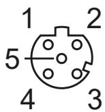 | 1 | Sensor supply (US) L+ |
| 2 | Digital input | |
| 3 | Sensor supply (US) L- | |
| 4 | C/Q IO-Link | |
| 5 | Not used |
Gate contact switch
Port X04 of the AL1326 is reserved for a gate contact switch:
• If the gate is open, ID tags are detected by the UHF gate.
- If the gate is closed, the UHF gate is in sleep mode and does not detect any ID tags.
Switch the UHF gate to sleep mode:
▶ Apply a high signal to the digital input of port X04.
Connect external PLC
Ports X01 and X02 of the AL1326 are used as standard for the OGP700 retro-reflective laser sensors. Alternatively, the ports can be used as digital inputs for an external PLC.
Further information on the digital inputs can be found in the AL1326 operating instructions: documentation.ifm.com
7.8 AL3050 pin assignment
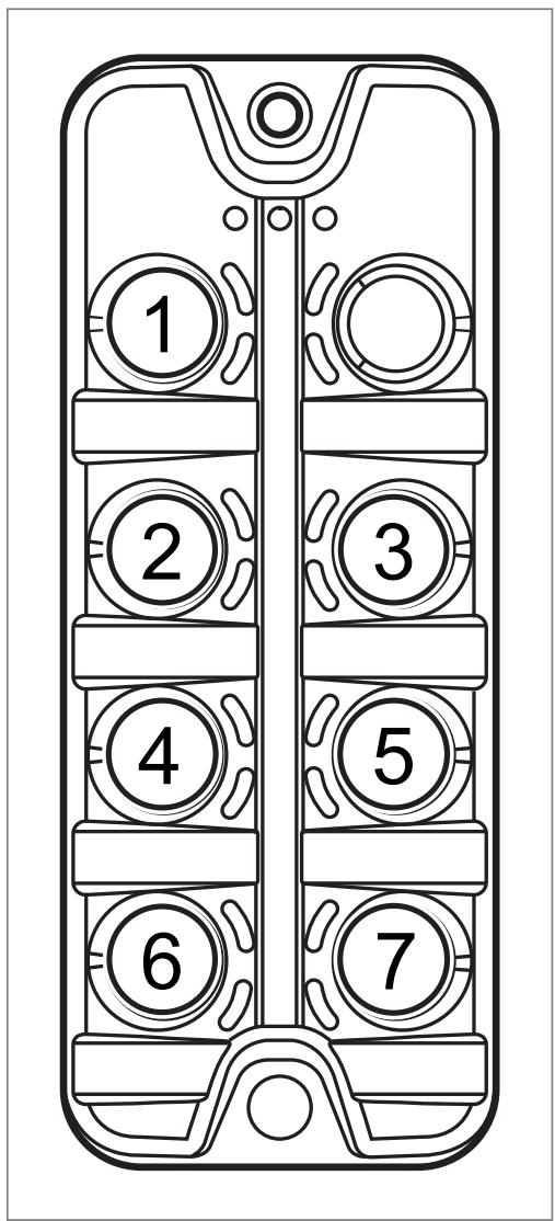
Fig. 8: AL3050 front side
1: Voltage supply X31
2: Ethernet X01
3: Ethernet X02
4: Ethernet X03
5: Ethernet X04
6: Ethernet X05
7: Ethernet X06
Voltage supply X31
| Pin assignment | Pin | Assignment |
 | 1 | +24 V DC (US) |
| 2 | Not used | |
| 3 | GND (US) | |
| 4 | Not used |
Ethernet X01.. X06
| Pin assignment | Pin | Assignment |
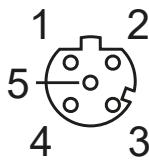 | 1 | TX+ |
| 2 | RX+ | |
| 3 | TX- | |
| 4 | RX- | |
| 5 | Not used |
7.9 O3D354 pin assignment

Fig. 9: O3D354 rear
1: Ethernet
2: Power supply and switching inputs/outputs
Ethernet
| Pin assignment | Pin | Assignment |
 | 1 | TX+ |
| 2 | RX+ | |
| 3 | TX- | |
| 4 | RX- |
Power supply and switching inputs/outputs
| Pin assignment | Pin | Assignment |
 | 1 | U+ |
| 2 | Trigger input | |
| 3 | GND | |
| 4 | Switching output 1 (digital or analogue) | |
| 5 | Switching output 3 / ready | |
| 6 | Switching output 2 (digital) | |
| 7 | Switching input 1 | |
| 8 | Switching input 2 |
8 Set-up
Before set-up, the units are to be mounted ( → Installation ☐ 11) and electrically connected ( → Electrical connection ☐ 14).
8.1 DTE830
The DTE830 is set using the UHF gate solution software. The software is used to set the DTE830 as a gate. In addition, the operating direction, the RFID reader and the RFID antennas are set.
The software is pre-installed on the edge
Controller ZZ1124. The software manual is available in the download area of the DTE830: documentation.ifm.com
Activating multiple gates
The gates must be activated one after the other:
▶ First activate the master gate and then the extension gates.

Simultaneous activation of the power supply to several gates causes connection problems
▷ If the power supplies of the gates are activated at the same time, the gates log on to the master gate with the same IP address. This causes the gates to be assigned incorrectly.
▶ Activate the power supplies of the gates one after the other.

Gate 1 is preset as the master gate.
8.2 O3D354
The O3D354 is set up with the ifm Vision Assistant software. The software, the software manual and the operating instructions are available in the download area of the O3D354: documentation.ifm.com
8.2.1 Connecting ifm Vision Assistant
▶ Connect the O3D354 to the ifm Vision Assistant software:
▶ Connect the O3D354 to the of the voltage supply and to the PC via Ethernet.
▷ See operating instructions, chapter "Electrical connection".

The following functions are described in detail in the software manual.
▶ Start the ifm Vision Assistant software.
▶ Select the [Find sensor] button.
▷ The [Find device] function searches for the O3D354 in the network and establishes a connection. The O3D354 is automatically assigned an IP address.
▶ Select the [Save] button:

8.2.2 Creating an application
Two applications must be created on the O3D354 using the ifm Vision Assistant software.
Direction detection and trigger application
Create the "Direction detection and trigger" application:
▶ Add a new application in the [Application] area.
▶ Select the [User defined mode] wizard for the new application.
▶ In the [Image settings] area, set the image of the O3D354 according to the installation situation.
▶ In the [Models] section, create a new [Level] model.
▷ Select the [Level model] [Underfilling].
▷ Select the [Measurement task] [ Maximum].
▶ For direction detection, create 2 [Search zones] (ROI) in front of the gate.
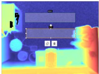
Fig. 10: View from top: 2 search zones (ROI) in front of the gate
▷ The search zone ROI 0 is orientated towards the stored goods in the warehouse.
▷ The ROI 1 search zone is aligned to the lorry.
▶ In the [Models] section, [measure] and [teach] the [Reference level].
▷ The area of the search zones must be free of objects when teaching the reference level.
▶ In the [Models] section, set the [switching thresholds] to the minimum object height.
▶ Automatically create a logic configuration in the [Logic] area.
▶ Check the behaviour of the switching thresholds in the [Overall test] area.
▶ Save the application.
▶ In the [Application] area, rename the application to "Direction detection and trigger".
▷ The application is created and tested.
Direction detection application and PAUSE mode trigger
Create the "Direction detection and PAUSE mode trigger" application:
▶ In the [Application] area, duplicate the "Direction detection and trigger" application.
▶ Edit the duplicated application.
▶ In the [Image settings] area, set the [Trigger] to [Process interface].
▶ Save the application.
▶ In the [Application] area, rename the application to "Direction detection and trigger PAUSE mode".
▷ The application is created.
8.3 ZZ1124
The UHF gate solution software is pre-installed on the edge
Controller ZZ1124. The software starts immediately after setting up the edge
Controller.
The software is described in the software manual. The software manual is available in the download area of the ZZ1124: documentation.ifm.com
8.3.1 Data exchange between ZZ1124 and higher-level system
Data is exchanged between the edge
Controller ZZ1124 and a higher-level system (ERP, MES, DCS) via feedback and result files. To do this, the UHF gate is set to the [Load control] or [Logging] function. A transfer method is then set for the function.
Load control
If the UHF gate is set to [Load control]:
• The data is provided.
- The system waits for a response from the higher-level ERP system. The response is sent as a result file from the connector program.

▶ Use the [File exchange] transfer method for the [Load control] gate function.
The [File exchange] transfer method provides a JSON file that contains the data read from the RFID goods receipt and goods registration system. The JSON file can be processed further.
Logging
If the UHF gate is set to [Logging]:
- The data from the readings is provided as a feedback file. As soon as >10 feedback files are available in the file system, the oldest one will be overwritten (ring buffer). Separate feedback files are provided for each gate.
- The system waits not for a response from the higher-level system.

▶ For the gate function [Logging], use the transmission method [File exchange] or [MQTT].
The [File exchange] transfer method provides a JSON file that contains the data read from the RFID goods receipt and goods registration system. The JSON file can be processed further.
The [MQTT] transmission method provides the data read from the RFID goods receipt and goods registration system to an MQTT broker. Clients connected to the MQTT broker can then retrieve and process the data.
8.3.1.1 File exchange with result file
If the gate function [Load control] and the transmission method [File exchange] are set, a result file is provided.

Fig. 11: Data exchange with results file
8.3.1.2 File exchange without result file
If the gate function [Logging] and the transfer method [File exchange] are set, no result file is provided.
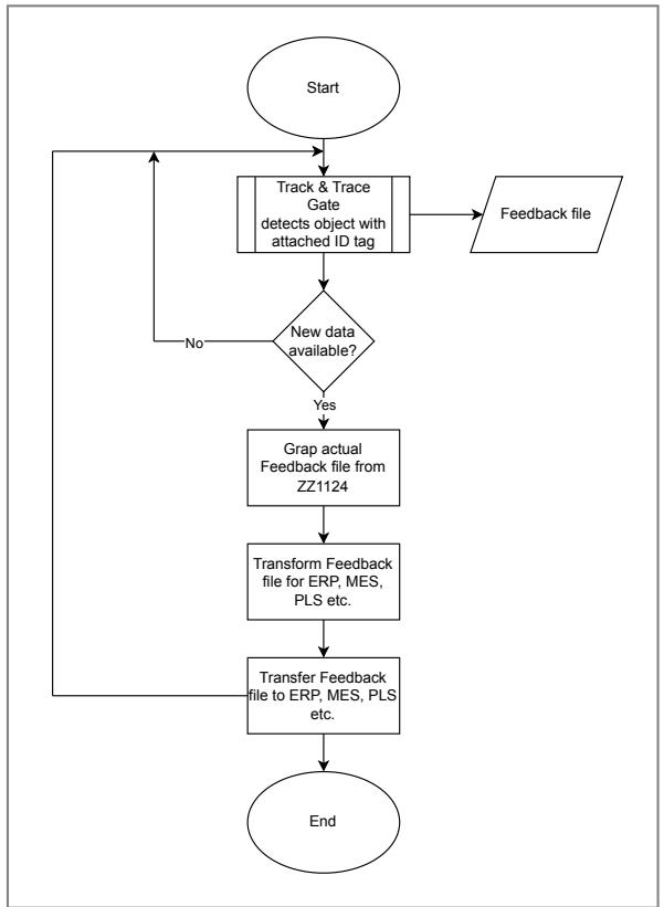
Fig. 12: Data exchange without result file
8.3.2 Structure of the feedback file
The feedback file generated by the ZZ1124 is saved in the JSON file format. The feedback file contains all the important information required by the higher-level system. The feedback file must be fetched from the file system of the ZZ1124 by the higher-level system and deleted.
The feedback file has the following structure:
| ID | Gate ID | Direction | EPC | TID | USER | ISO8601 (Time) |
| 1 | 490503 | IN | E2801114200087CB7700 2222 | / | / | 03/15/202113:14:30 |
| 2 | 490503 | OUT | E2801114200087AA7700 4265 | / | / | 03/15/202113:14:30 |
| 3 | 490402 | IN | E2801114200087AA7788 4265 | / | / | 03/15/202113:14:30 |
Id
Unique ID of the data record.
Gate ID
Unique ID (numerical value) of the gate. The gate ID is set in the gate configuration.
Direction
Loading direction (Direction
Type, Enum):
"θ": Incoming
"1": Outgoing
EPC
Electronic Product Code. Data on the ID tag assigned to a good.
TID
The transponder ID is a globally unique identification number of the ID tag.
The TID is currently not supported (as of 11/2021).
USER
The USER memory area is a memory area on the ID tag for application-specific data.
The USER memory area is currently not supported (as of 11/2021).
ISO8601 (Time)
Time stamp according to ISO 8601.
8.3.2.1 Examples
The following examples show data records from feedback files.
Example 1
[{"eventID":1,"gateID":490503,"direction":"IN","EPC":"E2801114200087CB77002222","TID":"E21F202100000000000000B","user":"","timestamp":"2021-03-15T13:14:30+0100"},
{"eventID":2,"gateID":490503,"direction":"IN","EPC":"E2801114200087CB77002223","TID":"E21F202100000000000C79F","user":"","timestamp":"2021-03-15T13:14:30+0100"},
{"eventID":3,"gateID":490503,"direction":"IN","EPC":"E2801114200087CB77002224","TID":"E21F20210000000000C714","user":"","timestamp":"2021-03-15T13:14:30+0100"},
{"eventID":4,"gateID":490503,"direction":"IN","EPC":"E2801114200087CB77002225","TID":"E21F2021000000000C723","user":"","timestamp":"2021-03-15T13:14:30+0100"}]}
Example 2
[{"eventID":5,"gateID":490502,"direction":"OUT","EPC":"E2801114200087CB77001234E21F2021000000000002AD5F","TID":"","user":"","timestamp":"2021-03-15T13:14:30+0100
Example 3
[{"eventID":6,"gateID":490512,"direction":"OUT","EPC":"E2801114200087CB77009876","TID":"E21F2021000000000001767B","user":"","timestamp":"2021-03-15T13:14:30+0100"}]
8.3.3 Structure of the results file
The higher-level system compares the feedback file with the stored delivery note. The higher-level system then sends its feedback back to the edge
Controller via a results file in JSON file format. The edge
Controller analyses the loading and unloading of goods via the results file.
The results file has the following structure:
| ID | Gate ID | direction | EPC | TID | USER | ISO8601 (time) | Result |
| 1 | 490503 | IN | E2801114200 087CB7700 2222 | / | / | 03/15/2021 13:14:30 | OK |
| 2 | 490503 | OUT | E2801114200 087AA7700 4265 | / | / | 03/15/2021 13:14:30 | Nok |
| 3 | 490402 | IN | E2801114200 087AA7788 4265 | / | / | 03/15/2021 13:14:30 | ok |
Id
Unique ID of the data record.
Gate ID
Unique ID (numerical value) of the gate. The gate ID is set in the gate configuration.
Direction
Loading direction (Enum):
"θ": Incoming
"1": Outgoing
EPC
Electronic Product Code. Data on the ID tag assigned to a good.
TID
The transponder ID is a globally unique identification number of the ID tag.
The TID is currently not supported (as of 11/2021).
USER
The USER memory area is a memory area on the ID tag for application-specific data.
The USER memory area is currently not supported (as of 11/2021).
ISO8601 (Time)
Time stamp according to ISO 8601.
Result
Displays the result of the evaluation with the higher-level system.
Result (UHFGateResults, Enum):
"OK 2: The item is in line with the plan."
"NOK": The item does not match the plan.
"ERROR": The item is incorrect or not in the system.
" COMPLETE": The delivery note was loaded completely without errors.
8.3.3.1 Examples
The following examples show data records from result files.
Example 1
[{"eventID":1,"gateID":490503,"direction":"IN","EPC":"E2801114200087CB77002222","TID":"E21F202100000000000000B","user":"","timestamp":"2021-03-15T13:14:30+0100","result":"OK"},
{"eventID":2,"gateID":490503,"direction":"IN","EPC":"E2801114200087CB77002223","TID":"E21F202100000000000C79F","user":"","timestamp":"2021-03-15T13:14:30+0100","result":"OK"},
{"eventID":3,"gateID":490503,"direction":"IN","EPC":"E2801114200087CB77002224","TID":"E21F202100000000000C714","user":"","timestamp":"2021-03-15T13:14:30+0100","result":"OK"},
{"eventID":4,"gateID":490503,"direction":"IN","EPC":"E2801114200087CB77002225","TID":"E21F20210000000000C723","user":"","timestamp":"2021-03-15T13:14:30+0100","result":"COMPLETE"}]
Example 2
[{"eventID":5,"gateID":490502,"direction":"OUT","EPC":"E2801114200087CB77001234E21F2021000000000002AD5F","TID":"","user":"","timestamp":"2021-03-15T13:14:30+0100","result":"COMPLETE"}]
Example 3
[{"eventID":6,"gateID":490512,"direction":"OUT","EPC":"E2801114200087CB77009876","TID":"E21F2021000000000001767B","user":"","timestamp":"2021-03-15T13:14:30+0100","result":"ERROR"}]
8.3.4 Retrieving the feedback file via SSH
The feedback file can be retrieved from the file system of the ZZ1124 via SSH. (→ Data exchange between ZZ1124 and higher-level system ☐ 25)
The following example shows how to retrieve the feedback file via SSH. The following settings are used for the example:
PORT: "22"
USER: "root"
PASSWD: "pdm3"
CODESYS_ROOT_PATH: "/home/cds-apps/JSONFiles/"
DATA_FILE: "./config/data.json"

Fig. 13: Sequence diagram of the SSH connection
Flow
-
The client tries to establish a connection to the ZZ1124 with q 2000 ms timeout.
-
The client reads and checks all new JSON files in the folder "/home/cds-apps/JSONFiles/" . The JSON files are then copied to a temporary folder.
-
The client compares and tags the registered ID tags from the host with the expected ID tags from the delivery note.
-
The client adds a ".result" suffix in the file name to the processed JSON files.
-
The client deletes all JSON files in the temporary folder.
8.3.5 MQTT
MQTT (Message Queueing Telemetry Transport) is an open network protocol for machine-to-machine (M2M) communication. It is used for communication with an ERP such as SAP. The transferred data is formatted in JSON. The data model and the interfaces follow the EPCIS standard (gs1.org).
| Device | EPCIS Scanner |
| Protocol | MQTTS/TLS |
| MQTT broker host and port | e7ff829e-a915-4650-a8ca-08005c2dc356.us10.cp.iot.sap:8883 |
| MQTT client ID | EPCISJSONMQTT |
| X.509 client certificate | |
| Client secret key | a! VxkUngDxmd#J6fzT09?#tr3nu9A6rK7?mt |
| Publishing topic | messages/EPCISJSONMQTT |
| Example of "Publish payload"(Example is optimised for ifm data structure) | { "EPCISBody":{ "Event List":[ { "Object Event":{ "event Time":"2020-11-03T20:35:31.116-06:00", "event TimeZoneOffset":"-06:00", "epcList":[ { "epc":"111234567000000204"möglich ist auch: urn:epc:id:sscc: 111234567000.000204 } ], "action":"IN",(direction) "read Point":"Dock1", "epcextension":[ { "EPC":"111234567000000204", "TID":"1", "USER":"ABC" } ] }} }}}}}}}}}}}}}}}}}}}}}}}}}}}}}}}}}}}}}}}}}}}}}}}}}}}}}}}}}}}}}}}}}}}}}}}}}}}}}}}}}}}}}}}}}}}}}}}}}}}}}}}}}}}}}}}}}}}}}}}}}}}}}}}}}}}}}}}}}}}}}}}}}}}}}}}}}}}}}}}}}}}}}}}}}}}}}}}}}}}}}}}}}}}}}}}}}}}}}}}}}} |
| Subscribable topic for confir-mation | ack/EPCISJSONMQTT |
8.4 DV2510
The signal light contains the following signalling elements:

1: LED segment 1
2: LED segment 2
3: LED segment 3
4: LED segment 4
5: LED segment 5
6: Buzzer
Fig. 14: Position of the display elements
Mode
The signalling light can be used in [Default Mode] or [Compatibility Mode].
Setting the mode is described in the ZZ1124 software manual: documentation.ifm.com
Default Mode
| LED segment | Colour | State | Description |
| (1) | green | Operating status | The gate is active. |
| Yellow | Pause | The gate was paused manually. | |
| red | Error | Error in the gate hardware, NTP, ERP etc. The gate has detected a goods transfer in the wrong direction. | |
| (2) | BlackLED segment not lit | BlackLED segment not lit | The LED segment (2) is not used in [Default Mode] and is not lit. |
| (3), (4) and (5) | BlackLED segment not lit | Wait for trigger | Wait for trigger. |
| blue | No ID tag | No ID tag detected, | |
| Yellow | Reading an ID tag | An ID tag is being read or a data transfer is active. | |
| (3), (4) and (5) | green | Result OK | The result of the goods turnover is OK and agrees with ERP. |
| red | Result not OK | The result of the goods turnover is not OK and does not match ERP. | |
| Purple | Goods handling completed | Goods handling is successfully completed and matches ERP. |
Compatibility Mode
| LED segment | LED behaviour | Colour | State | Condition ends when.. |
| (1) | Permanently. | green | The gate is active and waiting. | ... ID tags can be read. |
| Permanently. | Yellow | An ID tag is being read or a data transfer is active. | ... the reading of ID tags is finished. | |
| Permanently. | Red | The gate was paused manually. | ... pausing is ended manually. | |
| Permanently. | Red | Error in the gate hardware, NTP, ERP etc. The gate has detected a goods transfer in the wrong direction. | ... the error has been rectified. | |
| (2) | Permanently. | Green | The result of the goods turnover is OK and agrees with ERP. | ...new ID tags are read. |
| Flashes | red | The result of the goods turnover is not OK and does not match ERP. | ... the error has been rectified. | |
| (444 / 3) | Flashes | blue | No ID tag detected or ID tag is defective. | ... 15 s are over. |
| (4) | Permanently. | green | Goods handling is successfully completed and matches ERP. | ... 2 minutes have passed or new ID tags are read. |
| Permanent / flashing | Yellow | Goods handling is processed. The behaviour depends on the LED segment (2). | ... the goods handling is completed. |
9 Maintenance, repair and disposal
The unit is maintenance-free.
▶ Contact ifm in case of malfunction.
▶ Do not open the housing as the unit does not contain any components which can be maintained by the user. The unit must only be repaired by the manufacturer.
▶ Clean the device using a dry cloth.
▶ Dispose of the unit in accordance with the national environmental regulations.
10 Approvals/standards
For approvals and standards, the following information is available:
• Test standards and regulations: documentation.ifm.com
• EU declaration of conformity and approvals: documentation.ifm.com
• Notes relevant for approval: Package insert of the device and documentation.ifm.com
Glossary
ERP
ERP (Enterprise Resource Planning) refers to the planning, control and management of personnel, resources, capital, equipment, materials, information and communication technology, with the focus on an efficient operational value creation process and continuously optimised control of business and operational processes.
MQTT
MQTT (Message Queueing Telemetry Transport) is an open network protocol for machine-to-machine (M2M) communication. The protocol transmits telemetry data between devices in the form of messages. High delays and limited networks are not a problem. An MQTT server (broker) stores the data of the communication partners and can be used as a status database. This makes it possible to connect small, non-performant MQTT devices to an MQTT broker, with the devices collecting data or receiving commands. A complex situation picture is created on the MQTT broker. The situation picture can be analysed on the broker or by a powerful communication partner.
ROI
Region of Interest (ROI) is the area that is taken into account when evaluating the target reflections. Targets outside this area will not be taken into account. The area can be adjusted individually under the radar settings.
- 1 PRELIMINARY NOTE
- 1.1 SYMBOLS USED
- 1.2 WARNINGS
- 1.3 LEGAL AND COPYRIGHT INFORMATION
- 2 SAFETY INSTRUCTIONS
- 2.1 SAFETY INSTRUCTIONS FOR LOADING/UNLOADING
- 3 INTENDED USE
- 4 ITEMS SUPPLIED
- 5 FUNCTION
- 5.1 LOAD CONTROL
- 5.2 LOGGING
- 5.3 LOADING UNLOADING
- 6 INSTALLATION
- 6.1 INSTALLING SET ZZ0814
- 6.2 INSTALLING SET ZZ0816
- 6.3 INSTALLING SETS NEXT TO EACH OTHER WITH DIVIDER GRID
- 7 ELECTRICAL CONNECTION
- 7.1 CONNECTING THE ZZ0814
- 7.2 CONNECTING THE ZZ0815
- 7.3 CONNECTING THE ZZ0816
- 7.4 CONNECTING THE ZZ0817
- 7.5 ZZ1124 PIN ASSIGNMENT
- 7.6 DTE830 PIN ASSIGNMENT
- 7.7 WIRING AL1326
- 7.8 AL3050 PIN ASSIGNMENT
- 7.9 O3D354 PIN ASSIGNMENT
- 8 SET-UP
- 8.1 DTE830
- 8.2 O3D354
- 8.2.1 CONNECTING IFM VISION ASSISTANT
- 8.2.2 CREATING AN APPLICATION
- 8.3 ZZ1124
- 8.3.1 DATA EXCHANGE BETWEEN ZZ1124 AND HIGHER-LEVEL SYSTEM
- 8.3.1.1 FILE EXCHANGE WITH RESULT FILE
- 8.3.1.2 FILE EXCHANGE WITHOUT RESULT FILE
- 8.3.2 STRUCTURE OF THE FEEDBACK FILE
- 8.3.2.1 EXAMPLES
- 8.3.3 STRUCTURE OF THE RESULTS FILE
- 8.3.3.1 EXAMPLES
- 8.3.4 RETRIEVING THE FEEDBACK FILE VIA SSH
- 8.3.5 MQTT
- 8.4 DV2510
- 9 MAINTENANCE, REPAIR AND DISPOSAL
- 10 APPROVALS/STANDARDS
Brand : IFM
Model : ZZ0817
Category : RFID system