
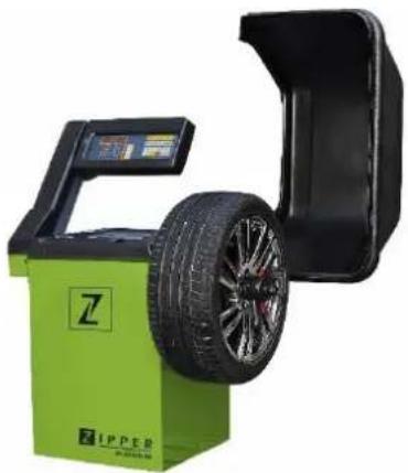
ZIRWM99 - Wheel balancer Zipper - Free user manual and instructions
Find the device manual for free ZIRWM99 Zipper in PDF.

| Product type | Semi-automatic wheel balancer |
| Brand | Zipper |
| Model | ZIRWM99 |
| Category | Wheel balancer |
| Power supply | 230 V / 50 Hz (according to nameplate) |
| Dimensions (approx.) | 800 x 600 x 900 mm |
| Weight (approx.) | 80 kg |
| Balancing type | Dynamic and static balancing |
| Main functions | Self-calibration, modes Normal, Static, ALU1, ALU2, ALU3, imbalance optimization, visual control of the rolling plane |
| Display | Digital with LEDs |
| Manual dimension input | Distance (a), width (b), diameter (d) |
| Wheel fixation | By cone and quick-release nut |
| Protective cover | With safety switch |
| Safety | Emergency stop, cover safety switch, grounding |
| Maintenance | Weekly screw check, safety label check, regular cleaning |
| Cleaning | Water and mild detergent, avoid solvents and high-pressure cleaners |
| Spare parts and repairability | Original parts recommended, 2-year warranty (DIY) / 1 year (pro), contact dealer |
| Error codes | Displayed on screen (e.g. #1 to #8), solutions in manual |
| Intended use | Balancing car and motorcycle wheels |
Frequently Asked Questions - ZIRWM99 Zipper
User questions about ZIRWM99 Zipper
0 question about this device. Answer the ones you know or ask your own.
Ask a new question about this device
Download the instructions for your Wheel balancer in PDF format for free! Find your manual ZIRWM99 - Zipper and take your electronic device back in hand. On this page are published all the documents necessary for the use of your device. ZIRWM99 by Zipper.
USER MANUAL ZIRWM99 Zipper
16.3.1 Mounting the threaded shaft 25
16.3.2 Mounting the hood 26
16.3.3 Connection to the power supply 27
16.3.4 Calibration 27
17 OPERATION 27
17.1 Mounting the tyre 27
17.2 Setting the dimension 28
17.2.1 Determining and setting the distance value (a) 28
17.2.2 Determining and adjusting the nominal size (b) 28
17.2.3 Determining and adjusting the nominal diameter (d) 28
17.3 Self-Calibration 29
17.4 Measuring unbalance 29
17.5 Recalculation of the unbalance 30
17.6 Minimizing static unbalance 30
17.7 Functions 30
17.7.1 Static - Alu 30
17.7.2 Optimizing an unbalance 30
17.7.3 Visual inspection of the running surface 31
18 MAINTENANCE 32
19 CLEANING 32
20 TRANSPORT 32
21 STORAGE 32
21.1 Disposal 32
22 TROUBLESHOOTING 33
22.1 Error Codes 33
22.2 Inconsistent unbalance measured values 33
23 PREDMLUVA (CZ) 34
24 BEZPECNOST 35
24.1 Ucel pouzití stroje 35
24.2 Pro yasi bezpečnost 35
25 ZACINAME 36
25.1 Rozbalte a zkontrolujte dodávku 36
25.2Nastaveni stroje 36
25.3 Sestava 36
EN EC-CONFORM: This product complies with the EC-directives.
EN READ THE MANUAL! Read the user and maintenance manual carefully and g familiar with the controls in order to use the machine correctly and to avoid injuries and machine defects.
EN Personal protective equipment!
EN Stop and pull out the power plug before any break and engine maintenance!
CZ Stoj (^r)udzbou a (^r)estavkami vypnete a odpoje ze sife!
EN Only trained staff!
EN Warning of rotating parts!
This operating manual contains information and important notes on commissioning and handling the ZI-RWM99 wheel balancer.
In the following, the commercial designation of the machine is replaced by the designation "machine" in the cover sheet of this operating manual.
The operating manual is part of the machine and must not be removed. Keep it for future reference and include these instructions with the machine if you pass it on to third parties!
Please observe the safety instructions!

Please observe the safety instructions!
Read these instructions carefully before putting the machine into operation. This facilitates proper handling and prevents misunderstandings and possible damage.
Follow the warnings and safety instructions. Failure to do so may result in serious injury and/or damage to the machine.
Due to constant further development of our products, illustrations and contents may differ slightly. If you find any errors, please inform us.
Subject to technical changes!
Copyright
© 2018
This document is protected by international copyright law. Any unauthorized duplication, translation or use of pictures, illustrations or text of this manual will be pursued by law. Court of jurisdiction is the Linz Regional court or the court responsible for 4707 Schlüsslberg, Austria!
Customer Service Address
This semi-automatic balancing machine is exclusively designed for balancing motorcycle or car wheels.
This machine is not intended for use by persons (including children) with limited physical, sensory or mental abilities or lack of experience and/or knowledge, unless they are supervised by a person responsible for their safety or receive instructions from them on how to use the machine.
Never allow children or persons not equipped with the necessary expertise to operate the machine.
ZIPPER-MASCHINEN assumes no responsibility or warranty for any use of the machine other than the intended use or for any resulting personal injury or property damage.
In particular inadmissible or forbidden is/are:
- the operation of the machine under conditions outside the limits specified in this manual
- changes in the construction of the machine
- the operation of the machine without the provided safety devices
- altering or rendering ineffective the safety equipment of the machine (protective devices)
- the operation of the machine in a manner or for purposes contrary to the instructions in this manual
15.2 For your safety
Only use the machine when it is in intact technical condition and in accordance with its intended purpose, safety and hazard awareness! Check the operational safety of the machine before each use. Immediately rectify any faults that could impair safety!
Warning signs and/or stickers on the machine that are illegible or have been removed must be replaced immediately!
Local laws and regulations may determine the minimum age of the operator and limit the use of this machine!
Observe the recommended operating, maintenance and repair measures and, without exception, observe the safety instructions contained in the manual for this machine.
In addition, observe the following general recommendations for safe working:
- Only place the machine on a stable surface that does not give way.
- Only operate the machine in sufficiently good lighting conditions.
- Always wear sturdy and non-slip footwear (safety shoes S1) and other suitable personal protective equipment (tight-fitting work clothing, protective gloves according to EN 388, class 3111).
- Do not work on the machine in case of fatigue, lack of concentration or under the influence of medication, alcohol or drugs!
Operation with jewelry, tie or long hair forbidden! - Never leave the running machine unattended!
If you pass the machine on to third parties, the instructions for the machine must be included.
.
To avoid malfunctions, damages and health impairments, the following safety instructions must also be observed unconditionally:

DANGER
A safety instruction of this type indicates an imminently dangerous situation which, if not avoided, will result in death or serious injury.

WARNING
This type of safety information indicates a potentially dangerous situation which, if not avoided, could result in serious injury or even death.

CAUTIO N
A safety note designed in this way indicates a potentially dangerous situation which, if not avoided, may result in minor or slight injuries.

NOTICE
Such a safety note indicates a potentially dangerous situation which, if not avoided, can lead to property damage.
Despite all safety regulations, your quick horse sense and appropriate technical suitability/training remains the most important safety factor when operating the machine!
16 GETTING STARTED
16.1 Unpacking and checking scope of delivery
Remove the protective carton. Immediately after unpacking, check whether the equipment is complete. Check if any parts have been damaged. If something is wrong or missing, do not use the machine and contact your retailer immediately. Later complaints due to transport damage or incomplete delivery can no longer be accepted.
16.2 Setting up the device
Select a suitable location for setting up the machine. The floor at the place of installation must be firm and level and be able to support the weight of the machine. In addition, the place of installation must comply with the applicable regulations for workplace safety and must have a suitable power connection.
Special anchoring of the machine to the ground is not necessary for correct operation.
16.3 Assembly
16.3.1 Mounting the threaded shaft
As standard the machine is supplied with a universal cone adapter. The spring built into the adapter body cannot be removed. The threaded shaft can be removed to allow the installation of alternative adapters, e.g. for motorcycle wheels.
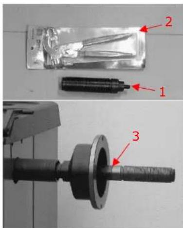
- Fasten the threaded shaft (1) to the main shaft (3) using the tool supplied (2).
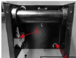
16.3.2 Mounting the hood

- Loosen the four screws on the back of the unit (shown in the picture on the left).
-
Position the bracket (4) and secure it with the previously loosened screws.
-
Attach the safety switch (5) to the bracket (as shown in the picture on the left).
-
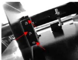
Connect the cable to the safety switch.
-
Insert hood rod into the hollow shaft and fasten it with the screws.
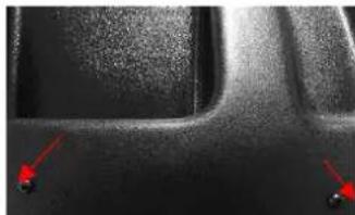
- Place hood to the hood rod and fix it with screws.
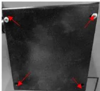
- Then put the cover onto the bracket and screw it tight (as shown in the picture on the left).

-
Slide a cone onto the threaded shaft and loosely tighten the quick-release nut.
-
The correctly mounted device now looks as shown in the picture on the left.
16.3.3 Connection to the power supply
WARNING
High electrical voltage! Connection of the machine to the power supply by persons who are not specially trained in the handling of electricity (electricians) can lead to serious injuries or death. The machine may therefore only be wired by persons specially trained for working with electricity (electricians)!
Observe the information on voltage and frequency on the type plate on the back of the machine!
It is recommended to provide the machine with its own electrical connection via a suitable circuit breaker.
The mains cable of the machine should be fitted with a plug that complies with the applicable regulations.
When connected directly to the mains control without plug, it is advisable to lock the main switch of the balancing machine with a padlock so that it can only be operated by authorised persons.
16.3.4 Calibration
For proper operation, the instrument must be calibrated after installation and connection to the power supply. In addition, calibration is always advisable if there are doubts about the correctness of the displayed measurement results.
17 OPERATION
17.1 Mounting the tyre
- Select the appropriate cone for the wheel center hole and slide it onto the threaded shaft.
- Slide the wheel onto the threaded shaft.
- Lock the wheel using the quick-release nut.
17.2 Setting the dimension
17.2.1 Determining and setting the distance value (a)
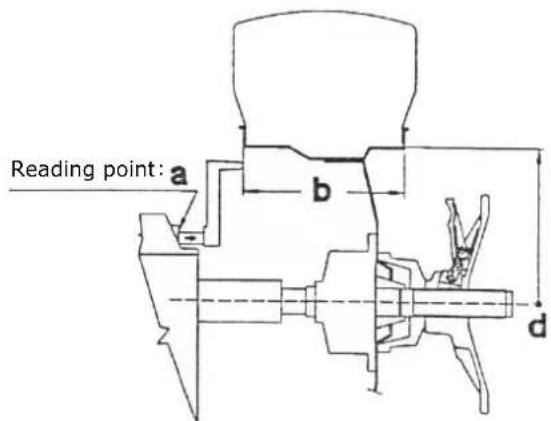

- Pull out the special gauge to the inner rim edge
(The increment of the scale is 0.5cm the full range is reached at 18 cm.)
-
Read the distance value from the scale.
-
Set the value a using the corresponding arrow keys on the control panel (MANUAL INPUT DISTANCE (a)) to the desired value.
17.2.2 Determining and adjusting the nominal size (b)
Set the nominal size (b). It usually can be found on the rim. If necessary, use the grab compass, to determine the nominal diameter (b) by placing the heads of the grab compass on the left and right side of the rim and reading the value from the scale on the grab compass (see diagram above).
The value is entered by pressing the MANUAL INPUT WIDTH key (b) on the control panel using the corresponding arrow keys.
The increment of the scale is 5 millimeters or for inch input 0.25 Inches. The following values are shown in the display (for inch-setting only):
.2 for 14 inches; .5 for 12 inches and .7 for 34 inches
17.2.3 Determining and adjusting the nominal diameter (d)
The nominal diameter is indicated on the tyres. Enter the value by pressing the MANUAL INPUT DIAMETER (d) key on the control panel using the corresponding arrow keys.
17.3 Self-Calibration

NOTICE
Entering the wrong dimensions will cause the machine to be incorrectly calibrated and all subsequent measurements to be incorrect until a new self-calibration with the correct dimensions is performed.
To self-calibrate the machine, proceed as follows:
- Mount any wheel on the shaft, even if it is not balanced; better still, if it has an average size.
- Set the exact dimensions of the wheel (a, b, d value).
| F + C → CAL | 3 Press the F and C button on the control panel simultaneously until the display shows CAL. | CAL. and the LEDs stop flashing. |
| START → Add | 4 Close the hood and press the START button. A complete turn is performed and the display shows Add 100. |
| 5 Attach a 100 gram reference weight to any position on the outside of the rim. | |
| 6 Press START again. | |
| START → End | 7. After a second cycle, the display shows END CAL. Now the calibration procedure is complete. |
| 8. Remove the reference weight and balance the wheel as described in the following section. |
The value measured by the machine during the self-calibration cycle is automatically kept in a special memory, which stores it even when the machine is switched off. This means that the machine is immediately ready for operation after being switched on again. Self-calibration should be carried out from time to time or if there are doubts about the correctness of the measured results.
17.4 Measuring unbalance
To perform an unbalance measurement, close the protective cover. Depending on the setting, also press the START button.
The wheel is brought up to speed within a few seconds, decelerated again and the unbalance values are displayed on the control panel.
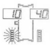
Slowly turn the wheel counterclockwise until all LED's of the digital display for the internal unbalance value light up. The correct position for attaching the weight is then exactly in the 12 o'clock position on the inside of the rim.


Then slowly turn the wheel clockwise until all the LED's on the digital display for the external unbalance value light up. The correct position for attaching the weight is then exactly in 12 o'clock position on the outside of the rim.
Note: Lightly pressing Button C in the 12 o'clock position displays the preset dimensions one after the other.
To measure again, close the hood after attaching the weights and press the START button if necessary.
17.5 Recalculation of the unbalance
To recalculate the unbalance, set the dimensions as described in chapter 17.2 Setting the dimension
Without repeating the measurement cycle press key C.
The newly determined unbalance values are displayed.
17.6 Minimizing static unbalance
For commercial weights with a gradation of five grams (5 g) each, static unbalances of up to 4 g can remain, as they fall below the sensitivity of the display. In such cases, the device displays zero. To display such "residual unbalances" (< 5 g), press the FINE key.
17.7 Functions
17.7.1 Static - Alu
The available functions indicate where the correction weights are to be placed in positions other than the normal positions. To select a specific function, press the ALU and F keys.
The unbalances are displayed according to the selected correction position.
| Symbol | Function | Description |
| Normal | The Normal function is used for balancing steel or light alloy rims by applying weights to the rim edges. | |
| Static | The Static function is required on motorcycle wheels or when it is not possible to place the weights on both sides of the rim. | |
| ALU1 | The ALU1 function is used to balance light alloy wheels by attaching the adhesive weights to the rim shoulders. | |
| from rim plane of rest | ALU2 | The ALU2 function is used for balancing light alloy wheels with concealed application of the outer adhesive weight. (The position of the external weight is as shown in the figure.) |
| ALU3 | Function ALU3 - Combined balancing: Attachment weight inside; concealed attachment of the adhesive weight outside. |
17.7.2 Optimizing an unbalance

NOTICE
Carry out the following steps with the utmost care in order to achieve the best possible result.
The optimization function is used to reduce the weight to be added to the wheel to balance it. This design is recommended if the static unbalance is more than 30 grams. In many cases this can improve the residual eccentricity of the wheel.
The function is called by pressing the OPT key (to exit, press the STOP key)
Press the Start key. The display shows the required rotation of the tyre (180irc) . Mark adapter and rim with chalk with a reference mark so that you are able to mount the rim in the same position again later. (Use index on the shaft.)
Turn the tyre 180irc on the rim using a tyre remover.
Refit the rim to the threaded shaft in the previous position.
Press the START key again.
Right display: Value of the possible reduction of the left unbalance in relation to the current wheel situation in percent. Left display: current static unbalance value in grams. (It is the value that can be reduced by a wheel-rim rotation.)
Turn the wheel until the outer LEDs light up.
Mark the tyre at the top (12 o'clock)
Also mark the border according to the position indicated by the inner LEDs.
In the example given here, the static unbalance of 45g is reduced by 80% with a remaining residual unbalance of approx. 9g .
17.7.3 Visual inspection of the running surface
To perform a visual inspection of the tread condition, it is necessary to rotate the wheel with the guard open.
Performing:
- Press the F key with one hand while pressing the START key with the other hand.
→ A complete cycle is performed. The function is then automatically deactivated.
18 MAINTENANCE
WARNING
Dangerous electrical voltage! The elimination of faults or defects by persons not specially trained in handling electricity (electricians) can result in serious injuries or even death. Therefore, malfunctions or defects may only be remedied by persons specially trained in working with electricity!
The machine requires little maintenance and only a few parts have to be serviced:
- Before each operation, check that the safety devices are in perfect condition.
- Check the screw connections for tightness at least once a week.
- Regularly check that the warning and safety labels on the machine are in perfect and legible condition and replace them if necessary.
Malfunctions or defects that could impair your safety may only be remedied by qualified personnel!
19 CLEANING

NOTICE
The use of solvents, aggressive chemicals or abrasives can lead to damage to paintwork and other property on the machine!
Free the machine from dust and other deposits after each use. Only use water and, if necessary, a mild detergent for cleaning! The use of compressed air or high-pressure cleaners is not recommended. The latter can reduce the operational suitability of the machine or shorten its service life, because water (moisture) could get inside the machine when it is used.
20 TRANSPORT

NOTICE
The wheel balancer may only be transported in its original packaging.
The wheel balancer may only be transported in its original packaging. Always switch off the motor before transport and allow the machine to cool down if necessary.
Use a forklift truck with suitable capacity to move the packed machine.
21 STORAGE
Thoroughly clean the machine before storage, empty liquid tanks if necessary and dispose of liquids in accordance with national regulations. Pack cleaned machine and store in a dry and clean place.
21.1 Disposal
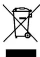
Observe the national waste disposal regulations. Do not dispose of the machine, machine components or equipment in residual waste. If necessary, contact your local authorities for information on the disposal options available.
If you buy a new machine or an equivalent device from your specialist dealer, he is obliged in certain countries to dispose of your old machine properly.
22 TROUBLESHOOTING
22.1 Error Codes
Certain errors occurring during operation are automatically detected by the device system and shown on the display by means of an error code - see table below:
| Error Code | Fault | Possible cause | Remedy |
| 1 | No rotation signal | Faulty position sensor, rotation obstacle (something prevents the wheel from turning) or faulty computer board | Replace position encoder Remove obstacle If necessary, contact your dealer. |
| 2 | Speed is less than 60 revolutions per minute | No wheel mounted, faulty position sensor or faulty computer board | Mounting tyres Replace position encoder If necessary, contact your retailer |
| 3 | Miscalculation | Incorrect self-calibration, excessive unbalance or faulty circuit board | Repeat self-calibration, check correct wheel centering on the shaft; contact your retailer if necessary |
| 4 | Wrong direction of rotation | Incorrect direction of rotation, faulty position encoder or faulty computer board | Replace position sensor, correct direction of rotation, contact your retailer if necessary |
| 5 | Faulty computer board | Faulty computer board | If necessary, contact your retailer |
| 7 | Card related error | Incorrect self-calibration or faulty computer board | Repeat self-calibration; contact your retailer if necessary |
| 8 | Memory error during self-calibration | Start of a second cycle without reference weight, crack in transformer cable, faulty computer board or faulty power supply board | Attach reference weight, replace transformer cable, contact your retailer if necessary |
22.2 Inconsistent unbalance measured values
When a wheel that has already been balanced is mounted again for balancing, it sometimes seems as if the wheel has not yet been balanced.
This is usually not due to an incorrect display of the machine, but to the mounting of the wheel on the adapter - i.e. in the two brackets the wheel has taken a different position in relation to the centre line of the balancing machine.
Small errors of up to ten grams (4 oz) are considered normal for wheels fixed by cones; for wheels locked with screws or bolts, the error is usually greater.
If the wheel is mounted on the adapter with screws, it may be that the screws are not tightened properly - they should be tightened one by one, or, as is often the case, holes have been drilled on the wheel with too much tolerance.
If a balanced wheel does not run smoothly after being reinstalled in the vehicle, this may also be due to an imbalance in the car brake drum or (very often) to holes drilled in the rim and drum bolts with excessive tolerances. In this case, rebalancing with the wheel mounted on the vehicle can be useful.
23 PREDMLUVA (CZ)
Vázéní zákaznici!
If wrong dimensions are entered, the machine will be incorrectly calibrated and all subsequent measurements will be incorrect until a new self-calibration with the correct dimensions is performed.
With original HOLZMANN spare parts you use parts that are attuned to each other shorten the installation time and elongate your products lifespan.
IMPORTANT
The installation of other than original spare parts voids the warranty!
So you always have to use original spare parts
When you place a spare parts order please use the service form you can find in the last chapter of this manual. Always take a note of the machine type, spare parts number and part name. We recommend to copy the spare parts diagram and mark the spare part you need.
You find the order address in the preface of this operation manual.
| N°. | Bezeichnung/Decryption | Qty. | N°. | Bezeichnung/Decryption | Qty. |
| 1 | Case | 1 | 24 | Keyboard | 1 |
| 2 | Stand column | 1 | 25 | M10x135 | 1 |
| 3 | Rotating shaft | 1 | 26 | Pressure ring screw | 1 |
| 4 | Hexa agon bolt M10x30 | 5 | 27 | Flat gasket 10x2 | 5 |
| 5 | Flat gasket 10x2 | 5 | 28 | Pressure sensor | 2 |
| 6 | Motor | 1 | 29 | Pressure spring | 1 |
| 7 | Motor plate | 1 | 30 | Box of wheel cover | 1 |
| 8 | Hex nut M6 | 13 | 31 | Shaft of wheel cover | 1 |
| 9 | Belt pulley | 1 | 32 | Travel switch | 1 |
| 10 | Measuring scale | 1 | 35 | Lead screwø36 | 1 |
| 11 | Head of measuring scale | 1 | 36 | Center pole of lead screw M10x160 | 1 |
| 12 | Short rubber gasket | 1 | 37 | Plate of computer board | 1 |
| 13 | Long rubber gasket | 1 | 38 | Cover of display | 1 |
| 14 | Elastic collar 25x1,2 | 2 | 39 | Support of wheel cover | 1 |
| 15 | Power board | 1 | 40 | Wheel cover | 1 |
| 16 | Capacitance | 1 | 41 | Cover of stand column | 1 |
| 17 | Position sensor bracket | 1 | 42 | Tool box cover | 1 |
| 18 | Posotopn sensor | 1 | 400 | Quick nut | 1 |
| 19 | Belt | 1 | 401 | Width of measuring scale | 1 |
| 20 | Tool hanging rod | 4 | 403 | Balance pliers | 1 |
| 21 | Hex nut M10 | 11 | 404 | 100g weight | 1 |
| 22 | Switch | 1 | 405 | Cones | 1 |
| 23 | Computer board | 1 |
Company ZIPPER Maschinen GmbH grants for mechanical and electrical components a warranty period of 2 years for amateur use; and warranty period of 1 year for professional use, starting with the purchase of the final consumer. In case of defects during this period, which are not excluded by paragraph 3, ZIPPER will repair or replace the machine at its own discretion.
2.) Report:
In order to check the legitimacy of warranty claims, the final consumer must contact his dealer. The dealer has to report in written form the occurred defect to ZIPPER. If the warranty claim is legitimate, ZIPPER will pick up the defective machine from the dealer. Returned shipments by dealers which have not been coordinated with ZIPPER, will not be accepted and refused.
3.) Regulations:
a) Warranty claims will only be accepted, when a copy of the original invoice or cash voucher from the trading partner of ZIPPER is enclosed to the machine. The warranty claim expires if the accessories belonging to the machine are missing.
b) The warranty does not include free checking, maintenance, inspection or service works on the machine. Defects due to incorrect usage of the final consumer or his dealer will not be accepted as warranty claims either. Some examples: usage of wrong fuel, frost damages in water tanks, leaving fuel in the tank during the winter, etc.
c) Defects on wear parts are excluded, e.g. carbon brushes, collection bags, knives, cylinders, cutting blades, clutches, sealings, wheels, saw blades, splitting crosses, riving knives, riving knife extensions, hydraulic oils, oil/air/fuel filters, chains, spark plugs, sliding blocks, etc.
d) Also excluded are damages on the machine caused by incorrect or inappropriate usage, if it was used for a purpose which the machine is not supposed to, ignoring the user manual, force majeure, repairs or technical manipulations by not authorized workshops or by the customer himself, usage of non-original ZIPPER spare parts or accessories.
e) After inspection by our qualified personnel, resulted costs (like freight charges) and expenses for not legitimated warranty claims will be charged to the final customer or dealer.
f) In case of defective machines outside the warranty period, we will only repair after advance payment or dealer's invoice according to the cost estimate (incl. freight costs) of ZIPPER.
g) Warranty claims can only be granted for customers of an authorized ZIPPER dealer who directly purchased the machine from ZIPPER. These claims are not transferable in case of multiple sales of the machine.
4.) Claims for compensation and other liabilities:
The liability of company ZIPPER is limited to the value of goods in all cases. Claims for compensation because of poor performance, lacks, damages or loss of earnings due to defects during the warranty period will not be accepted. ZIPPER insists on its right to subsequent improvement of the machine.
67 ZARUKA (CZ)
1.) Záruka:
We monitor the quality of our delivered products in the frame of a Quality Management policy.
Your opinion is essential for further product development and product choice. Please let us know about your:
- Impressions and suggestions for improvement.
- experiences that may be useful for other users and for product design
- Experiences with malfunctions that occur in specific operation modes
We would like to ask you to note down your experiences and observations and send them to us via FAX, E-Mail or by post
Please describe amongst others in the problem: What has caused the problem/defect, what was the last activity before you noticed the problem/defect? For electrical problems: Have you had checked you electric supply and the machine already by a certified electrician?
3. Bitebeachten
Additional information
INCOMPLETELY Filled SERVICE FORMS CANNOT BE PROCESSED! FOR GUARANTEE CLAIMS PLEASE ADD A COPY OF YOUR ORIGINAL SALES/ DELIVERY RECEIPT OTHERWISE IT CANNOT BE ACCEPTED. FOR SPARE PART ORDERS PLEASE ADD TO THIS SERVICE FORM A COPY OF THE RESPECTIVE EXPLODED DRAWING WITH THE REQUIRED SPARE PARTS BEING MARKED CLEARLY AND UNMISTAKABLE. THIS HELPS US TO IDENTIFY THE REQUIRED SPARE PARTS FASTLY AND ACCELERATES THE HANDLING OF YOUR INQUIRY.

- OPERATION 27
- MAINTENANCE 32
- CLEANING 32
- TRANSPORT 32
- STORAGE 32
- Please observe the safety instructions!
- Copyright
- Customer Service Address
- For your safety
- DANGER
- WARNING
- CAUTIO N
- NOTICE
- GETTING STARTED
- Unpacking and checking scope of delivery
- Setting up the device
- Assembly
- Mounting the threaded shaft
- Mounting the hood
- Connection to the power supply
- Calibration
- OPERATION
- Mounting the tyre
- Setting the dimension
- Determining and setting the distance value (a)
- Determining and adjusting the nominal size (b)
- Determining and adjusting the nominal diameter (d)
- Self-Calibration
- Measuring unbalance
- Recalculation of the unbalance
- Minimizing static unbalance
- Functions
- Static - Alu
- Optimizing an unbalance
- Visual inspection of the running surface
- MAINTENANCE
- CLEANING
- TRANSPORT
- STORAGE
- Disposal
- TROUBLESHOOTING
- Error Codes
- Inconsistent unbalance measured values
- PREDMLUVA (CZ)
- Vázéní zákaznici!
- IMPORTANT
- The installation of other than original spare parts voids the warranty!
- 2.) Report:
- 3.) Regulations:
- 4.) Claims for compensation and other liabilities:
- ZARUKA (CZ)
- 1.) Záruka:
- Bitebeachten
- Additional information
Brand : Zipper
Model : ZIRWM99
Category : Wheel balancer