USER MANUAL E7015S IFM
Original operating instructions AS-i Safety PCB
- According to the machine directive 2006/42/EC the original operating instructions and a translation of these operating instructions into the language or languages of the EU user country must be provided when a unit or protective system is put into operation within the member countries of the European Union (EU).
- If no operating instructions or EC declaration of conformity is supplied with this product in the language of the EU user country, these can be requested from your dealer (see delivery note) or manufacturer (see cover sheet / back).
- Only qualified personnel is allowed to set up the product. Furthermore, we expressly point out that any liability is excluded resulting from putting the unit into operation without the corresponding operating instructions in the language of the EU user country.
ES Espanol
Safety instructions 3
Installation / Set-up. 4
Installation / Electrical connection 5
Response times 8
Consideration of the residual error probability to IEC 61508 .8
Addressing. 9
Operation 9
Limited voltage 9
Scale drawing 11
Safety instructions
Follow the operating instructions.
Non-observation of the instructions, operation which is not in accordance with use as prescribed below, wrong installation or handling can affect the safety of people and machinery.
For installation and prescribed use of the unit the notes in the operating instructions must be carefully observed and the applicable technical standards relevant for the application have to be considered.
In case of non-observation of notes or standards, specially when tampering with and/or modifying the unit, any liability is excluded.
The unit must be installed, connected and put into operation by a qualified electrician trained in safety technology.
After installation the system has to be subjected to a complete function check. Disconnect the unit externally before handling it. Also disconnect any independently supplied relay load circuits.
Installation must be in accordance with EN 60204 and EN 62026-2.
If an AS-i network is controlling a machine with potentially dangerous movements and EN 60204-1 applies, a special insulation monitoring device must also be installed.
In case of malfunction of the unit please contact the manufacturer. Tampering with the unit can seriously affect the safety of operators and machinery. This is not permitted and leads to an exclusion of liability and warranty.
GB
Installation / Set-up
Applications
The AS-i safety PCB is used for the detection of safety-related switching states, e. g. 1-channel or 2-channel mechanical contacts. For this purpose a code table is transferred via the AS-i system with 8 × 4 bits which is evaluated by the AS-i safety monitor.
When operated correctly, the system can be used in applications up to the control category 4 according to EN 954-1 or IEC 61508/SIL3 (see notes Electrical connection).
Attention!

Depending on the safety components used the complete safety system might also be classified for a lower control category.
Function and electrical connection
Observe all information in the description of the configuration software and the operating instructions of the AS-i safety monitor. These documents provide all required instructions concerning installation, configuration, operation and maintenance of the AS-i safety system.
Information on the parameterisable safety functions of the AS-i safety PCB can be found in the chapter "Monitoring devices" of the configuration software manual.
Important note:

The products described herein are designed to be components of a safety-oriented machine or control system. A complete safety-related system normally includes sensors, evaluation units, signalling devices and safe switching outputs. It is the responsibility of each manufacturer of a machine or installation to ensure a correct functioning of the whole system. The manufacturer of the AS-i safety PCB, his subsidiaries and affiliates are not in a position to evaluate all of the characteristics of a given plant or machine which was not designed by him.
The manufacturer accepts no liability for any recommendation that may be implied or stated herein.
The warranty contained in the contract of sale is the sole warranty. Any statements contained herein do not create new warranties or modify existing ones.
Compliance with the description of the configuration software, the operating instructions of the AS-i safety monitor and the operating instructions of the AS-i safety module are mandatory!
Maintenance requirement

A minimum of one testing per year is compulsory by a demand on the safety function!
Installation / Electrical connection
Connect the AS-i safety PCB to two mechanical (positively driven) NC contacts. In doing so, the two outer black connection wires are connected to one side of the NC contacts. The other side of the NC contacts is connected with the other two black wires.
The AS-i safety PCB must be installed in a protected location (e.g. control cabinet, housing). The appropriate housing must have a protection rating of at least IP54. The unused bare wires must be insulated. A set-up test must be carried out after installation of the AS-i safety PCB.

When the AS-i safety PCB is mounted, cross faults between the connections of the mechanical contacts must be prevented. The connection wires of the AS-I safety PCB must not be extended.
For a classification to EN 954 category 4 or EN 61508 SIL3, positively driven mechanical contacts to EN IEC 60947-5-1, rated for a voltage >120V and a current >0.8A , must be connected.
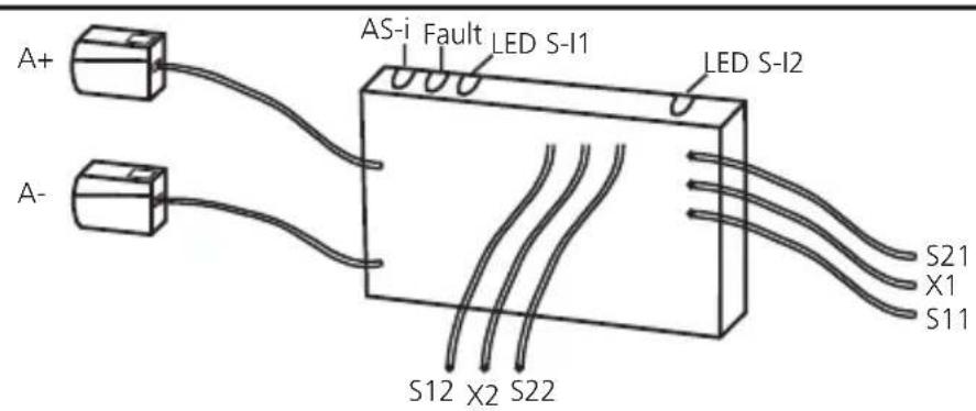
| Wiring |
| A+: AS-i + | | S11 S21 |
| A- AS-i - | |
| S11-S12 / S21-S22: switching input mechanical contact S-I1 / S-I2 | S12 S22 |
| LEDs 1: switching status indication inputs S-I1, S-I2 | X1 + Y2 |
| LEDs 2: AS-i, FAULT | |
| X1-X2: external LED alarm output |
The connected switching contacts must be configured as normally closed. The connection of two positively driven or two dependent switching contacts must be made to the wires S11 - S12 and S21 - S22.
The connection of two independent switching contacts is made to the wires S11 - S12 or to the wires S21 - S22.
An external alarm LED can be connected between wire X1 (red) and wire X2 (blue).
Data bits
| Data bit D3 D2 | D1 D0 | | | |
| In/Out SI-2 SI-2 | SI-1 SI-1/O-1 | | | |
| Activated input channel Bit sequence D3-D0 |
| SI-1 XX00 | |
| SI-2 00XX | |
| SI-1 and SI-2 0000 | |
| None XXXX | |
| Activated alarm outputs Bit sequence D3-D0 |
| O-1 XXX1 | |
GB
X = random
The code words 0000, XX00 and 00XX cause the AS-i safety monitor to bring the installation into the safe state.
For more details on the effect of the data bits on the transmission sequence refer to the configuration software manual (see the chapter "Monitoring devices").
Note:
If only one single-channel switch is to be connected to the module, it is to be connected to the input SI-1. The second input SI-2 must be bridged. Connect the wires S21 - S22.
Attention!
The wiring influences the achievable control category.
The requirements for external wiring and the selection of the connected switching contacts refer to the functionality to be accomplished and to the required control category (EN 954-1/ISO 13849-1 or EN/IEC 61508). The control category is either determined by means of a risk analysis (e.g. to EN 1050) or taken from a C standard. The control category or SIL level of the AS-i safety monitor must at least correspond to the control category or SIL level necessary for the application.
Response times
The response time of the safety PCB to a safety request is max. 10 ms.
Calculation of the total response time
For the calculation of the response time of the total system the response times of the other components also have to be added (mechanical switching contacts, data transmission, safety monitor and external relays or contactors possibly connected to the monitor output).
Example:
The response time of the E7015S to a safety request is max. 10 ms. In addition, the response time of the safety monitor has to be taken into account which is max. 40 ms including data transfer.
The sum of the individual response times results in a total response time of max. 50 ms before application of the signal to E7015S until the safe outputs of the safety monitors switch. Here, the switching times of the mechanical contacts (e-stops) and external relays or contactors possibly connected to the relay output of the safety monitor have not been taken into account.
Consideration of the residual error probability to IEC 61508
To calculate the PFH (probability of a dangerous failure per hour) of a safety-related function the PFH values of all components used in this function must be taken into account.
The probability of a dangerous failure per hour (PFH) is
1.8 × 10^-10 / h (per hour).
The maximum service life (T) is 10 years. The unit meets the requirements for SIL 3.
Explanation of the abbreviations:
- PFH = probability of a dangerous failure per hour
- SIL = safety integrity level
- T = life time (= service life)
The PFH values of the other components, especially of the AS-i safety monitor, can be found in the corresponding documentation.
Addressing
When mounted and wired the PCB can be addressed via the addressing unit AC1154.
Assign a free address between 1 and 31. At the factory the address is set to 0.
Operation
Check whether the unit operates correctly. Display by LEDs:
| · LEDs 1 yellow: inputs switched | (S-I1, S-I2) |
| · LED 2 green: voltage supply OK | (K PWR) |
| · LED 2 red lit: AS-i communication | on error, slave does not participate in the "normal" exchange of data, e.g. slave address 0 (FAULT) |
| · external LED alarm output (X1-X2): | alarm output O-1 (non-safe) (through the host system the alarm output LED can be set as a static or dynamic output) |

Core colours
AS-i +: brown
AS-i-:blue
S11, S12 S-I1 (safe input 1), black #1
S21, S22 S-I2 (safe input 2), black #2
X1: red + signal for LED output
X2: blue - signal for LED output
Limited voltage
The device shall be supplied from an isolating transformer having a secondary Listed fuse rated 5 A.
Technical data
| Electrical design 2 safe inputs / 1 unsafe LED output |
| Operating voltage 26.5 ... 31.6 V DC |
| Current consumption [mA] ≤ 50 mA |
| Inputs |
| Wiring DC PNP |
| Voltage supply via AS-i |
| Short circuit detection no |
| Input current typ. 5 mA |
| Cross fault monitoring no |
| LED output |
| Supply via AS-i yes |
| Integrated watchdog yes |
| Short-circuit proof no |
| Current rating LED output 10 mA |
| LED function display |
| Operation / fault / function green / red / yellow |
| Operating temperature -25...60°C |
| Protection rating depending on the housing |
| AS-interface / extended address mode possible | version 2.1 / no |
| AS-i profile | S-7.B.E |
| I/O configuration / ID code 7 [Hex] / B.E [Hex] |
| AS-i certificate | 74601 |
| Maximum number of safety modules per master | 31 |
| EMC | EN 50295 |
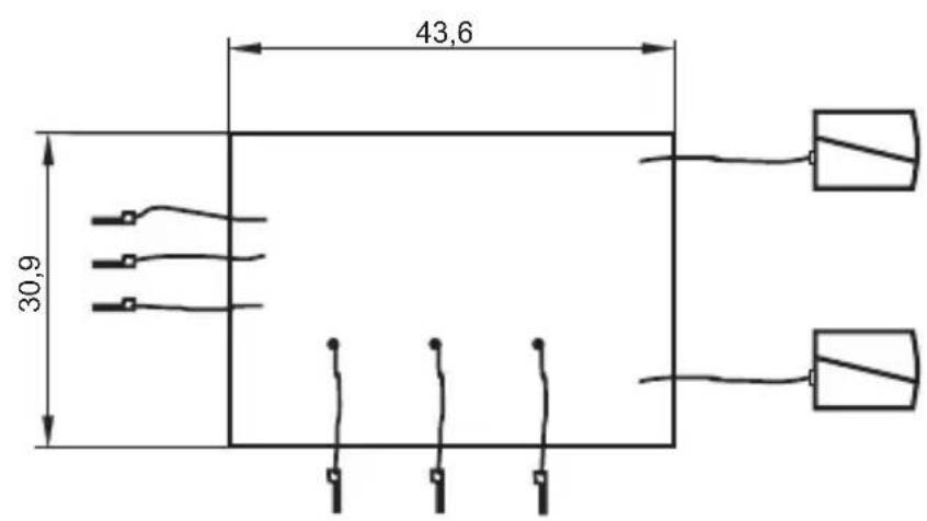
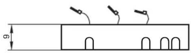
| Dimensions (WxHxD) | 30.9 X 9 X 43.6 mm |
Scale drawing
GB

Contenu