
AC2729 - Electronic board IFM - Free user manual and instructions
Find the device manual for free AC2729 IFM in PDF.
| Product type | Electronic card |
| Brand | IFM |
| Model | AC2729 |
| Category | AS-i printed circuit board |
| Main function | Detection of two non-safety switching states (mechanical contacts) |
| Number of inputs | 2 |
| Input type | Mechanical contacts (normally open or normally closed) |
| Power supply | Via AS-i bus |
| Supply voltage | 30 V DC (AS-i bus) |
| Required enclosure protection rating | IP54 minimum |
| LED display | LED 1 yellow (inputs I1, I2 switched), LED 2 green (PWR) and red (FAULT), external LED output X1-X2 |
| Addressing | Programmable address from 1A/1B to 31A/31B via addressing unit AC1144 |
| Data bits | D0 = I-1/O-1, D1 = I-2, D2/D3 unused |
| Connection | Black wires I1-1, I1-2, I2-1, I2-2; insulate unused stripped wires |
| Mounting | In a protected location (electrical cabinet or IP54 enclosure) |
| Maintenance and cleaning | Periodically check connections and proper operation |
| Safety | Insulate unused stripped wires; perform a commissioning test after installation |
| Manual available | Yes, free in PDF format on notice-facile.com |
Frequently Asked Questions - AC2729 IFM
User questions about AC2729 IFM
0 question about this device. Answer the ones you know or ask your own.
Ask a new question about this device
Download the instructions for your Electronic board in PDF format for free! Find your manual AC2729 - IFM and take your electronic device back in hand. On this page are published all the documents necessary for the use of your device. AC2729 by IFM.
USER MANUAL AC2729 IFM
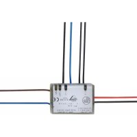
natural_image
Pure electrical circuit lines without any symbolsFunction and features
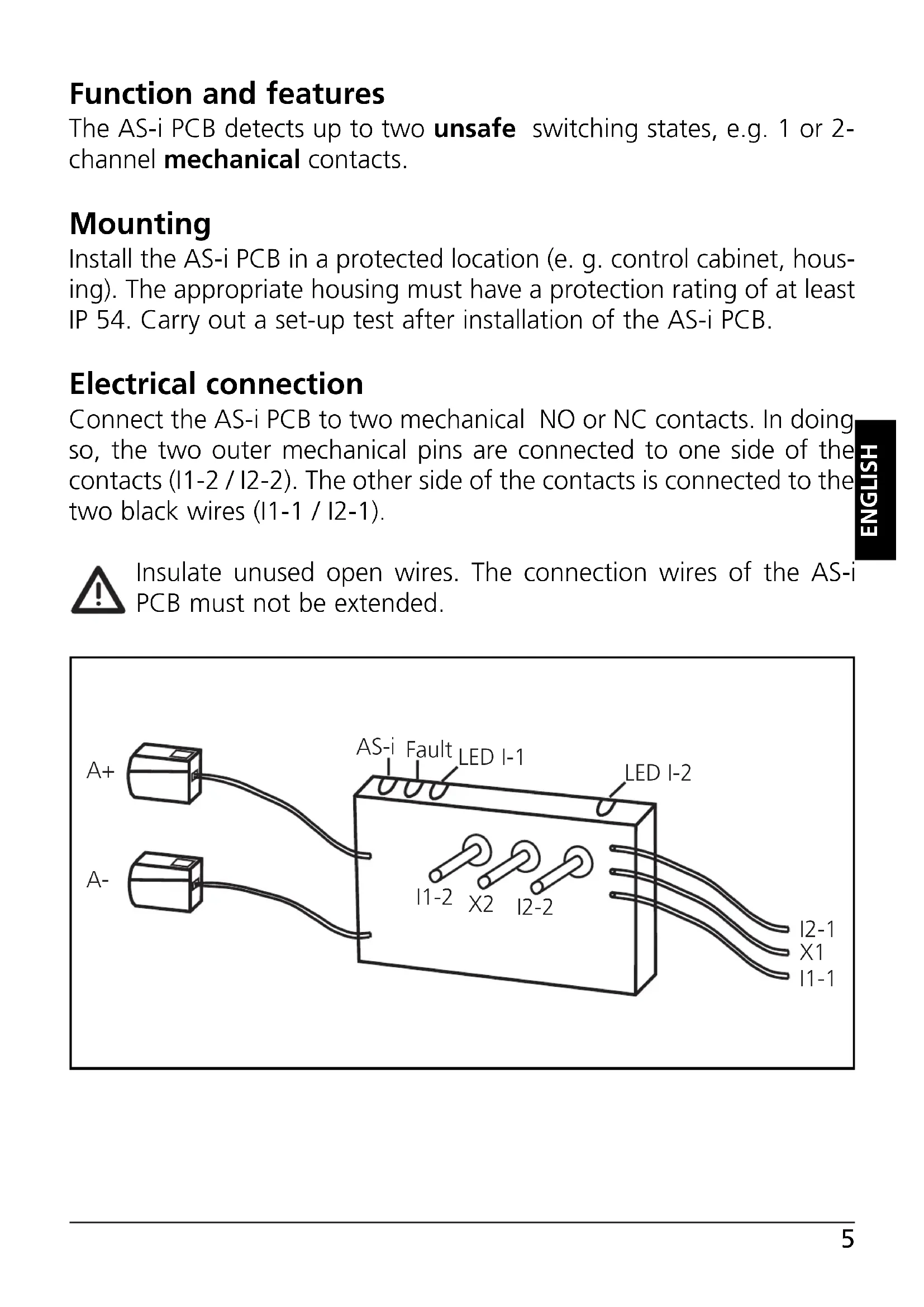
The AS-i PCB detects up to two unsafe switching states, e.g. 1 or 2-channel mechanical contacts.
Mounting
Install the AS-i PCB in a protected location (e. g. control cabinet, housing). The appropriate housing must have a protection rating of at least IP 54. Carry out a set-up test after installation of the AS-i PCB.
Electrical connection
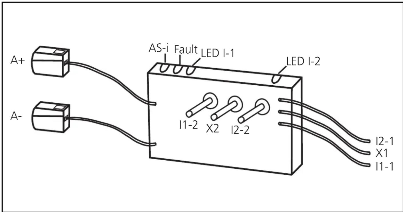
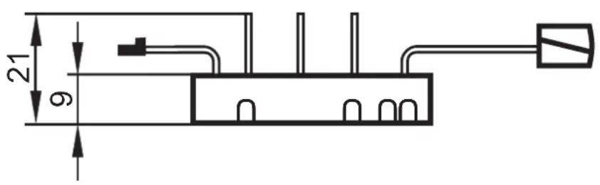
Connect the AS-i PCB to two mechanical NO or NC contacts. In doing so, the two outer mechanical pins are connected to one side of the contacts (I1-2 / I2-2). The other side of the contacts is connected to the two black wires (I1-1 / I2-1).

Insulate unused open wires. The connection wires of the AS-i PCB must not be extended.
Wiring
A+: AS-i +
A-: AS-i -
11-1/11-2
I2-1/I2-2: switching input mechanical contact I1 / I2
LEDs 1: switching status indication inputs I1, I2
LEDs 2: AS-i, FAULT
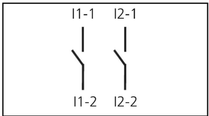
X1-X2: external LED output
Data bits
| Data bit | D0 | D1 | D2 | D3 |
| In/Out | I-1/O-1 | I-2 | - | - |
Addressing
When mounted and wired the PCB can be addressed via the addressing unit AC1144 using the cable (E70032).
Assign a free address between 1A/1B and 31A/31B. At the factory the address is set to 0.
If a slave with the extended addressing mode is used in combination with a master of the first generation (version 2.0), the parameter P3 must be 1 and the output bit D3 must be 0*. The output bit D3 and the parameter bit P3 must not be used.
* Default setting
If a slave with the extended addressing mode is used in combination with a master of the first generation (version 2.0), an address between 1A and 31A must be assigned to this slave.
Operation
Check the reliable functioning of the unit. LED display:
• LEDs 1 yellow: inputs switched (I1, I2)
• LED 2 green: voltage supply ok (PWR)
• LED 2 red lights: AS-i communication error, slave
does not participate in the “normal” exchange of data, e.g. slave address 0 (FAULT)
- External LED output (X1-X2): output O-1
(The output LED can be set as a static or dynamic output by the host system)
Limited voltage
The device shall be supplied from an isolating transformer having a secondary Listed fuse rated 5.0 A.
Technical data
You can download the data sheet from our website at www.ifm.com.
Scale drawing
Brand : IFM
Model : AC2729
Category : Electronic board