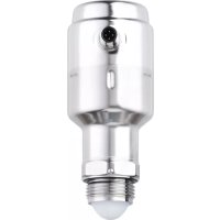
LW2720 - Sound level meters IFM - Free user manual and instructions
Find the device manual for free LW2720 IFM in PDF.


User questions about LW2720 IFM
0 question about this device. Answer the ones you know or ask your own.
Ask a new question about this device
Download the instructions for your Sound level meters in PDF format for free! Find your manual LW2720 - IFM and take your electronic device back in hand. On this page are published all the documents necessary for the use of your device. LW2720 by IFM.
USER MANUAL LW2720 IFM
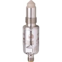
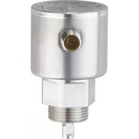
Operating instructions Electronic level sensor
LW2720
Contents
1 Preliminary note 4
1.1 Symbols used 4
1.2 Warnings used 4
2 Safety instructions.... 5
3 Intended use.... 6
3.1 Application area 6
3.1.1 Application examples 6
3.2 Restriction of the application area 7
4 Function 9
4.1 Measuring principle.... 9
4.1.1 Reflectivity, effect of dielectric constant.... 9
4.1.2 Foam and turbulence 10
4.1.3 Influence of vessel characteristics and installation 10
4.2 IO-Link 10
4.3 Outputs.... 10
4.3.1 Analogue output 10
4.3.2 Switching function.... 11
4.3.3 Defined state in the event of a fault (alert mode).... 12
4.3.4 Simulation function 13
4.3.5 Damping function 13
4.4 Output response in different operating states 13
5 Mounting.... 14
5.1 Mounting position 14
5.2 Inclination 15
5.3 Polarisation and orientation.... 15
5.4 Beam angle and beam width.... 15
5.5 Tank with conical bottom (emptying hopper).... 16
5.6 Non-metallic tanks. 16
5.7 Nozzle requirements.... 16
5.8 Notes for hygienic applications 17
5.8.1 Notes on the use according to EHEDG 17
5.8.2 Notes on the use according to 3-A® 18
5.9 Mounting in a threaded connection 18
5.10 Mounting preparations 18
5.10.1 Remove the protective cap 18
5.10.2 Place the O-ring, grease the thread 19
5.10.3 Premount the adapter for pipe fittings (dairy coupling, DIN 11851) ..... 20
5.10.4 Preparations when using a welding adapter 21
5.11 Mount the unit in the tank 22
5.11.1 Mount the unit with Tri Clamp adapter.... 22
5.11.2 Mount the unit with pipe fitting (dairy coupling, DIN 11851)....23
5.11.3 Mount the unit with VARIVENT® adapter 24
5.11.4 Install the weld-in adapter on the unit 25
5.11.5 Mount the unit with G1 connection 25
6 Electrical connection.... 26
7 Parameter setting 27
7.1 Parameter setting via PC and IO-Link master 27
7.2 Parameter setting during operation 27
7.3 Parameter setting via Bluetooth adapter 28
7.4 Adjustable parameters 28
7.5 System commands 33
7.6 Example parameter setting 33
8 Operation 35
8.1 Function check 35
8.1.1 Detection quality check 35
8.2 Diagnostic messages, cause, troubleshooting.... 35
9 Troubleshooting 37
9.1 Troubleshooting incorrect level readings.... 37
9.1.1 Level too high / too low 37
9.1.2 Measured value is stuck 37
9.1.3 Measured value drops when level close to antenna 38
9.1.4 Measured value fluctuates 39
9.1.5 Measured value is occasionally unstable 40
9.1.6 Lagging of measured value during rapid level changes.... 40
9.1.7 Measured value correct at 0% (4 mA) but incorrect at 100% (20 mA) ..... 41
9.1.8 Incorrect measured value when level is above 50% 41
9.1.9 Measured value drops to zero close to tank bottom 41
9.1.10 Level measurement is lost in an empty tank 42
9.1.11 Alert mode when level close to tank bottom 43
10 Maintenance, repair and disposal 44
11 Factory setting 45
12 Appendix.... 46
12.1 Approvals and certificates 46
1 Preliminary note
You will find instructions, technical data, approvals and further information using the QR code on the unit / packaging or at www.ifm.com.
1.1 Symbols used
√ Requirement
Instructions
Reaction, result
[...] Designation of keys, buttons or indications
→ Cross-reference

Important note
Non-compliance may result in malfunction or interference.

Information
Supplementary note
1.2 Warnings used

CAUTION
Warning of personal injury
▷ Slight reversible injuries may result.
2 Safety instructions
- The unit described is a subcomponent for integration into a system.
- The system architect is responsible for the safety of the system.
-
The system architect undertakes to perform a risk assessment and to create documentation in accordance with legal and normative requirements to be provided to the operator and user of the system. This documentation must contain all necessary information and safety instructions for the operator, the user and, if applicable, for any service personnel authorised by the architect of the system.
-
Read this document before setting up the product and keep it during the entire service life.
- The product must be suitable for the corresponding applications and environmental conditions without any restrictions.
- Only use the product for its intended purpose (→ Intended use).
- Only use the product for permissible media (→ Technical data).
- If the operating instructions or the technical data are not adhered to, personal injury and/or damage to property may occur.
- The manufacturer assumes no liability or warranty for any consequences caused by tampering with the product or incorrect use by the operator.
- Installation, electrical connection, set-up, operation and maintenance of the product must be carried out by qualified personnel authorised by the machine operator.
- Protect units and cables against damage.
- The standards the unit complies with include TLPR and CISPR 11. Further standards and specifications: → data sheet.

Radiated microwave energy:
The microwave energy radiated by the unit is far below that of mobile phones.
Maximum radiated energy: 2 mW.
According to the current state of science the operation of the unit can be classified to be harmless to human health.

CAUTION
With high process temperatures, parts of the unit may get hot.
▷ Risk of burns
▶ Do not touch the unit.
▶ Protect the housing against contact with flammable substances and unintentional contact.
▶ Allow the unit and process adapter to cool down before maintenance.
3 Intended use
The device monitors continuously and without contact the level of liquid media in closed tanks made of metal, concrete or similar housing structures.
Restriction of the application area ( → ☐ 7)
Bulk materials are detected depending on their properties (conical heaps, grain size, dielectric constant, etc.).
In addition, the following is necessary for installation and operation:
- Mounting material (→ Accessories)

Only use accessories from ifm electronic gmbh! The optimum function is not ensured when using components from other manufacturers.

Available accessories: www.ifm.com.
3.1 Application area
Non-contacting radar technology is ideally suited for food and beverage applications as it is maintenance-free, has a top-down installation that reduces the risk of leakages, and is unaffected by process conditions such as density, viscosity, temperature, pressure and pH.
The unit combines the innovative 80 GHz technology with the FMCW method and smart algorithms to maximise measurement accuracy and reliability, even in small tanks and challenging fast-filling / fast-emptying vessels.
3.1.1 Application examples

Storage tank:
Provides insight into the tank and ensures production runs smoothly without interruption.

Mixing tank:
Ensures correct filling and storage levels in tanks with agitators.

Batch filling:
Optimises the batch filling process.

CIP process:
The unit withstands standard CIP cycles and SIP cycles up to 140\ °C .
Optimisation of cleaning agent storage.
3.2 Restriction of the application area
- The device is not approved for use in potentially explosive atmospheres.
- The unit is not suitable for some bulk materials (e.g. coffee beans) due to their often very low dielectric constant.
- Detection of bulk materials with a higher dielectric constant (e.g. grist due to its higher moisture content) may be possible. See: Reflectivity, effect of dielectric constant ( → ☐ 9)
▶ Check the function by performing an application test. Note the influence of conical heaps and similar effects.
▶ The device may only be installed in accordance with the applicable national and international radio regulations and statutory provisions ( → package leaflet). For the scope of Directive 2014/53/EU, this means: the unit is a TLPR device. TLPR (Tank Level Probing Radar) equipment are devices designed to measure the level only in an enclosed space (i.e. metal tanks, concrete tanks or similar enclosure structures made of comparable damping material).
- Use preferably in metal tanks. When used in electrically non-conductive tanks:
– there may be deterioration caused by electromagnetic interference from other devices (noise immunity according to EN 61326-1).
- or if the mounting position is unfavourable, nearby objects outside the tank may cause disturbing echoes.
Incorrect measurements may be caused by the following media:
• heavily foaming or turbulent surfaces.
- media which are very inhomogeneous, separate from each other thus forming separation layers (e.g. oil layer on water).
▶ Check the function by performing an application test.
▶ Installation in a steady area.
▷ In case of permanent signal loss, the unit generates an error message and switches the outputs to a defined state.
4 Function
4.1 Measuring principle
The measuring principle of the unit is Frequency Modulated Continuous Wave (FMCW). The unit continuously emits electromagnetic waves in the GHz range with a constantly varying frequency towards the medium surface. Since the transmitter continuously changes the frequency of the transmitted signal, there will be a difference in frequency between the transmitted and the reflected signals ( → Fig. Measuring principle). The frequency of the reflected signal is subtracted from the frequency of the signal transmitted at that moment, resulting in a low frequency signal which is proportional to the distance to the medium surface. This signal is further processed to obtain fast, reliable, and highly accurate level measurements.

Δf d = distance
A: frequency (GHz)
B: time (s)
C: transmitted signal
D: reflected signal
Fig. 1: Measuring principle
Due to the 80 GHz technology used, the unit generates a very focused signal beam (beam angle approx. 10° ). This extends the range of possible applications and enables installation even in small tanks and confined spaces (e.g. in tanks with agitators, heating coils, etc.).
4.1.1 Reflectivity, effect of dielectric constant
The reflectivity of the medium has a substantial effect on the reflected signal (echo amplitude). The reflectivity is directly dependent on the dielectric constant of the medium. A high dielectric constant provides better reflectivity, thus improving the performance of the level measurement. This also indirectly affects the maximum achievable level measuring range. Minimum dielectric constant: → Data sheet
| Dielectric constant (also: relative permittivity) of some media | |
| Air (reference quantity) | 1 |
| Water | ≈ 80 |
| Salt water | ≈ 32 |
| Water, demineralised | ≈ 30 |
| Beer brew | ≈ 25 |
| Vinegar | ≈ 24 |
| Maize starch | ≈ 18 |
| Coarse soya flour, 19% moisture | ≈ 18 |
| Coarse soya flour, dry (application test recommended) | ≈ 3 |
| Vegetable oil (application test recommended) | ≈ 2...4 |
| Grist (application test recommended) | ≈ 2...3 |
| Malt (application test recommended) | ≈ 2...3 |
| Skimmed milk powder (application test recommended) | ≈ 2 |
| Coffee beans (not detected reliably) | ≈ 1.5 |
4.1.2 Foam and turbulence
Foaming liquids or turbulence may cause weak and varying echo amplitudes. Surface turbulence is not normally a problem unless it is excessive.
Measurement in foamy applications depends largely on the foam properties. If the foam is light and airy, the actual level is measured. For heavy and dense foam, the unit may measure the level of the foam's upper surface.
4.1.3 Influence of vessel characteristics and installation
The unit should be mounted so that objects such as heating coils, ladders and agitators are not in the radar signal path. These objects may cause false echoes which can affect the measurement and lead to measurement errors. However, the unit has built-in functions designed to reduce the influence from disturbing objects where such objects cannot be totally avoided. Vertical and inclined structures cause minimal effect since the radar signal is scattered rather than directed back to the antenna.
4.2 IO-Link
The unit has an IO-Link communication interface which requires an IO-Link capable module (IO-Link master).
The IO-Link interface enables direct access to the process and diagnostic data and provides the possibility to set the parameters of the unit during operation.
In addition, communication is possible via a point-to-point connection with a USB IO-Link master.
The IODDs necessary for the configuration of the unit, detailed information about process data structure, diagnostic information, parameter addresses and the necessary information about the required IO-Link hardware and software can be found at www.ifm.com.
4.3 Outputs
The unit generates output signals according to the parameter setting. Two outputs are available:
• OUT1: switching output / IO-Link
• OUT2: analogue output 4...20 mA or switching output (configurable)
4.3.1 Analogue output
The unit provides an analogue signal proportional to the level (according to NAMUR NE43, DIN IEC 60381-1) or a switching signal on output OUT2. The analogue output can be configured.
• Parameter [ou2] = [I] sets output OUT2 as analogue output.
• Parameter [ASP2] sets at which measured value 4 mA are provided.
• Parameter [AEP2] sets at which measured value 20 mA are provided.
- If [ASP2] is set lower than [AEP2], a rising curve results; if [ASP2] is set higher than [AEP2], a dropping curve results ( → Fig. Analogue output).
Minimum distance between [ASP2] and [AEP2] = 20 % of the active zone

Fig. 2: Analogue output
A: Upper blind zone, configurable. Adjustable parameters ( → ☐ 28)
I: current
B: zone with reduced accuracy
L: level
C: recommended measuring range
1: rising curve ([ASP2]<[AEP2])
D: zero point = reference point
2: dropping curve ([ASP2]>[AEP2])
Note the tolerances and accuracies during the evaluation of the analogue signal ( → data sheet).
4.3.2 Switching function
Via switching output OUT1 (factory setting) or additionally via OUT2 (can be set) the unit signals that a set limit level has been reached or that the level is below the limit. The following switching functions can be selected:
- hysteresis function / normally open or normally closed ( → Fig. Single-point mode and fig. Two-point mode)
- window function / normally open or normally closed (→ Fig. Window function)
The hysteresis function can be applied in single-point mode and in two-point mode. Functionally, both modes are the same; only the setting method differs.
The explanations below refer to output OUT1.
Hysteresis function single-point mode:
▶ [SSC1 Config. Mode] must be set to [Single point].
▶ First the set point [SSC1 Param. SP1] is set, then the hysteresis [SSC1 Config. Hysteresis] with the requested difference ( → Fig. Single-point mode).
The normally open or normally closed function is set by [SSC1 Config. Logic]: [no] = normally open / [nc] = normally closed.
Hysteresis function two-point mode:
▶ [SSC1 Config. Mode] must be set to [Two point].
▶ [SSC1 Param. SP1] sets the set point and [SSC1 Param. SP2] sets the reset point ( → Fig. Two-point mode).
The normally open or normally closed function is set by [SSC1 Config. Logic]:
[no] = normally open / [nc] = normally closed.

Fig. 3: Single-point mode

Fig. 4: Two-point mode
L: level
t: time
HY: hysteresis
Window function:
▶ [SSC1 Config. Mode] must be set to [Window].
The width of the window can be set by means of the difference between [SSC1 Param. SP1] and [SSC1 Param. SP2] ( → Fig. Window function).
The normally open or normally closed function is set by [SSC1 Config. Logic]: [no] = normally open / [nc] = normally closed.
If desired, a hysteresis can be set at the window limits using [SSC1 Config. Hysteresis].

L: level
t: time
W: window
Fig. 5: Window function
The limit values [SSCx Param. SPx] are always absolute to the zero point = reference point (Fig. Analogue output). The hystereses [SSCx Config. Hysteresis] are always relative to the limit values.
For the switching outputs, a switch-on and switch-off delay of max. 60 s can be set (e.g. for especially long pump cycles). The switch-on delay always refers to the limit value, the switch-off delay always refers to the hysteresis.
4.3.3 Defined state in the event of a fault (alert mode)
For output OUT2, a state in the event of a fault can be defined.
If a fault is detected or if the signal quality is below a minimum value, the unit changes into the alert mode and output OUT2 passes into a defined state according to NAMUR recommendation (NE43). For this case, the response of the output can be set via the parameter [FOU2].
The unit can pass into the alert mode with a delay. This can be useful if short-term errors occur or the signal is reduced briefly (below the minimum value), e.g. due to turbulence or foam formation. The delay time can be set (parameter [Alert mode delay time]). During the delay time the last measured value is frozen. If the measured signal is received again in sufficient strength within the delay time, the
unit continues to work in normal operation. If, however, it is not received again with sufficient strength within the delay time, the unit passes into the alert mode and output OUT2 changes into the defined state.

In case of heavy foam build-up and turbulence, consider the option of creating a steady area.
4.3.4 Simulation function
Various levels can be simulated for set-up, maintenance or interference reduction. The duration of the simulation can be selected (1 min...1 h). The simulation can be started manually and runs until it is stopped manually or the set time elapses. During the simulation the outputs respond according to the simulated process values.
4.3.5 Damping function
With unstable level (e.g. turbulence, wave movements), the output response can be damped. During damping the determined level values are smoothed by means of a mean filter; the result is a steady curve.
Damping can be set by means of the parameter [dAP].
[dAP] indicates in seconds after what time 63 % of the final value is reached in the event of a sudden jump. After 5 x [dAP] almost 100 % has been reached.
4.4 Output response in different operating states
| OUT1 | OUT2* | |
| Initialisation | OFF | OFF |
| Normal operation | according to the level and [ou1] and [SSC1...] settings | according to the level and [ou2], [ASP2] and [AEP2] settings |
| Fault / alert mode | OFF | < 3.6 mA at [FOU2] = [OFF]> 21 mA at [FOU2] = [On] |
| * If analogue output [ou2] = [I] has been selected. If the switching function has been selected: see column OUT1. | ||
| Additional information about the analogue output | ||
| Full signal | With rising curve | 20...20.5 mA |
| With dropping curve | 4...3.8 mA | |
| Empty signal | With rising curve | 4...3.8 mA |
| With dropping curve | 20...20.5 mA | |
5 Mounting

CAUTION
With high process temperatures, parts of the unit may heat up.
▷ Risk of burns
▶ Do not touch the unit.
▶ Protect the housing against contact with flammable substances and unintentional contact.
▶ Allow the unit and process adapter to cool down before maintenance.


Careful handling of the antenna
▶ Be careful not to scratch or otherwise damage the antenna.

Before installing and removing the unit:
▶ Make sure that no pressure is applied to the system. Also always take into account the potential dangers related to extreme machine and medium temperatures.
▶ Before installing the unit, observe the following mounting specifications.
5.1 Mounting position

The device may only be installed in accordance with the applicable national and international radio regulations and statutory provisions ( → package leaflet). For the scope of Directive 2014/53/EU, this means: The unit is a TLPR device. TLPR (Tank Level Probing Radar) equipment are devices designed to measure the level only in an enclosed space (i.e. metal tanks, concrete tanks or similar enclosure structures made of comparable damping material).
▶ Observe the following when selecting the mounting position:
- For optimal performance, the unit should be installed in locations with a clear and unobstructed view of the medium surface.
- The unit should be mounted with as few internal structures as possible within the signal beam.
- Do not mount the unit close to or above the inlet stream (→ Fig. Mounting).
- Do not position the unit directly above a side manway door.

Fig. 6: Mounting
▶ Distance to wall (D): Dmin = 200 mm (8 inch).
▶ Recommended: 1/2 of tank radius.
5.2 Inclination

Fig. 7: Inclination
▶ Mount the unit vertically (90°) to ensure a good echo from the medium surface.
▶ Maximum inclination (1): 3° (Fig. Inclination).
5.3 Polarisation and orientation
The device emits electromagnetic waves for level detection. The polarisation is the direction of the electrical component of these electromagnetic waves.

Fig. 8: Polarisation visualised from above
1: Polarisation plane
2: LW2xxx level sensor visualised from above
3: M12 electrical connector
4: 45° = optimum orientation of the device when installed close to the tank wall.
5: Tank wall

When the housing is rotated, the direction of polarisation changes and possibly the influence of the false echo on the measured value.
▶ In case of disturbing objects in the tank: Operation ( → ☐ 35), Troubleshooting ( → ☐ 37)
5.4 Beam angle and beam width
▶ Mount the unit with as few internal structures as possible within the signal beam.

Fig. 9: Beam angle and beam width
Beam angle ( α ): 10°
Beam width (W) as a function of the distance (D):
| Distance (D) | Beam width (W) |
| 2 m (6.6 ft.) | 0.4 m (1.2 ft.) |
| 4 m (13.1 ft.) | 0.7 m (2.3 ft.) |
| 6 m (19.7 ft.) | 1.1 m (3.5 ft.) |
| 8 m (26.2 ft.) | 1.4 m (4.6 ft.) |
| 10 m (32.8 ft.) | 1.8 m (5.8 ft.) |

The signal beam may penetrate the side wall of non-metallic tanks. Non-metallic tanks ( → ☐ 16)
▷ Such materials are largely transparent to the radar signal. Nearby objects outside the tank may cause disturbing radar echoes.
5.5 Tank with conical bottom (emptying hopper)


In case of tanks with a conical bottom, it can be an advantage to mount the unit in the centre of the tank to enable the measurement down to the bottom.
In case of centric mounting, especially with curved tank lids, interference from the tank (resonance) may occur in individual cases.
▶ Check the function by performing an application test
▶ If possible, mount the unit off-centre (eccentrically).
5.6 Non-metallic tanks
The unit may only be used in non-metallic tanks if, at the same time, the applicable national and international radio regulations and statutory provisions are adhered to (→ package leaflet). In particular, sufficient damping must be ensured, e.g. by the enclosure material or additional, suitable measures.
Nearby objects outside the container may cause interfering radar echoes, as such materials may be transparent to radar waves to some extent. Corrective measures:
▶ The unit should be positioned so that objects close to the tank are kept outside the signal beam.
When installed in non-metallic tanks, there may be deterioration caused by electromagnetic interference from other devices. Corrective measures:
▶ Apply a shielding screen / metal foil between the level sensor and other electrical devices.
▶ Additional installation in a metal pipe. Consider the beam angle of the unit when selecting a pipe diameter.
5.7 Nozzle requirements
▶ To allow the radar waves to propagate undisturbed, the specified nozzle dimensions should be observed ( → Fig. Nozzle dimensions and table).
▶ The lower end of the nozzle should be rounded to avoid false echoes and make it easy to clean.
▶ The inside of the nozzle must be smooth (i.e. avoid bad welding, rust, or deposit).

Fig. 10: Nozzle dimensions
Maximum nozzle height (H) as a function of the nozzle diameter (D):
| Nozzle diameter (D) | Nozzle height (H) |
| 40 mm (1.5 in.) | 150 mm (5.9 in.) |
| 50 mm (2 in.) | 200 mm (7.9 in.) |
| 80 mm (3 in.) | 300 mm (11.8 in.) |
| 100 mm (4 in.) | 400 mm (15.8 in.) |
| 150 mm (6 in.) | 600 mm (23.6 in.) |
5.8 Notes for hygienic applications
The unit withstands standard CIP routines and SIP routines up to 140 °C.
▶ To conform with applicable hygienic standards and food and beverage legislation and regulations, make sure:
– the unit is installed in a closed tank.
– the unit is installed with hygienic adapter and O-ring/seal.
▶ It is the responsibility of the user to ensure:
- the materials used (→ Data sheet) are suitable for the media to be detected and the cleaning/sanitising processes.
– the installation of the unit is drainable and cleanable. - that the joint/clamping between the unit and the nozzle is compatible with the tank pressure and media.
- that for the application an M12 connector with appropriate ingress protection against dirt and moisture is used.
5.8.1 Notes on the use according to EHEDG
The unit is suited for CIP (cleaning in process) when installed correctly.
▶ Observe the application limits (temperature and material resistance) according to the data sheet.
▶ Ensure that the installation of the unit in the system complies with EHEDG guidelines.
▶ Use self-draining installation.
▶ Only use process adapters permitted according to EHEDG with special seals required by the EHEDG position paper.
The gasket of the system interface must not be in contact with the sealing point of the sensor.
▶ In case of structures in a tank, the installation must be flush mount. If not possible then direct water jet cleaning and cleaning of dead spaces must be possible.
▶ Install leakage ports so that they are clearly visible.

1: Leakage port
2: Seal
▶ To avoid dead space adhere to the dimensions:
L lt; (D - d)
d = 2 5 mm
5.8.2 Notes on the use according to 3-A®
▶ Make sure that the sensor is integrated into the system according to 3-A.
▶ Use only adapters with 3-A qualification and marked with the 3-A symbol. Available accessories: www.ifm.com.
The process connection must be provided with a leakage port. This is ensured when installed using adapters with 3-A approval.
▶ Install leakage ports so that they are clearly visible.
▶ It is recommended to choose an installation position where the probe and the process connection can be cleaned with a spray ball.
For use according to 3-A, special regulations apply for cleaning and maintenance.
Not suitable for systems that have to meet the criteria of E9.2 of the 3A standard 63-04.
5.9 Mounting in a threaded connection

Fig. 11: Threaded mounting
Thread length requirements (A) for the G1 process connection on the tank:
| Required thread length (A) | |
| Amin | 8 mm (0.32 in.) |
| Amax | 16 mm (0.63 in.) |
5.10 Mounting preparations
5.10.1 Remove the protective cap
The protective cap protects the antenna from impacts during transport and storage.

▶ Before installing, carefully remove the protective cap.

▶ Be careful not to scratch or otherwise damage the antenna.
5.10.2 Place the O-ring, grease the thread
The matching O-ring (EPDM) is supplied with the adapter. More O-rings are available as accessories.

▶ Place the O-ring in the groove of the unit.

▶ Lightly grease the thread of the unit with lubricating paste.
The paste must be approved for the application and compatible with the elastomers used.
5.10.3 Premount the adapter for pipe fittings (dairy coupling, DIN 11851)

▶ Slide the coupling nut up over the bottom of the unit.

▶ Make sure that the O-ring is mounted in the groove of the unit.
▶ Screw the adapter onto the unit until it is hand-tight.
▶ Secure the unit and adapter using a vice.

Use suitable vice jaws (protectors). Do not over-tighten the vice as it might damage the adapter.

▶ Tighten firmly. ▶ Recommended tightening torque: 35 Nm.
Further tightening may affect the sealing. Replace the O-ring or the entire process connection if the seal area is damaged.
5.10.4 Preparations when using a welding adapter

Due to their fixed orientation, welding adapters limit the possibility to rotate the unit in case of false echoes in the tank: Measured value is stuck ( → ☐ 37)
▶ If possible: give preference to clamp adapters and similar adapters that can be rotated / aligned.
Install the welding aid:
The welding aid absorbs heat during the welding process and can prevent warping of the weld-in adapter.

CAUTION
During the welding operation, the adapter and the welding aid can increase in temperature to over 65\ °C ( 149\ °F ).
▷ Risk of burns
▶ Let the components of the welding aid and weld-in adapter cool down before removal.

▶ Hand-tighten the weld-in adapter on the welding aid.

▶ Insert the clamping bolt through welding aid opening.

▶ Mount the counter plate.

▶ Hand-tighten the nut.
Weld the weld-in adapter to the tank:
Welding operation:
▶ During welding and the following cooling phase the unit must not be in place.
▶ During welding, avoid overheating of the adapter and observe sufficient cooling phases.
▶ While welding, the adapter must not warp.
▶ The sealing edge of the adapter must not be damaged by weld spatter or similar. Ensure sufficient protection of the sealing edge before starting the welding process.

▶ Fix the adapter in several spots with a sufficient adhesive force. Apply the fixing points at equal distances opposite each other.

▶ Apply the welding seams between the fixing points opposite each other. Ensure sufficient intervals between the individual sections to avoid glowing through or warping of the adapter due to overheating.
▶ Allow the adapter and the welding aid to cool.
▶ If used: Remove the welding aid.
▶ Remove deposits from the thread.
5.11 Mount the unit in the tank

▶ Be careful not to scratch or otherwise damage the antenna.
5.11.1 Mount the unit with Tri Clamp adapter
▶ Make sure that the O-ring is mounted in the groove of the unit.
▶ Screw the Tri Clamp adapter onto the unit (not shown). Tighten to the recommended torque ( → Installation instructions of the adapter).

▶ Place a suitable gasket on top of the tank flange.
The inner diameter of the selected clamp gasket must correspond to the inner diameter of the tank flange. The inside of the gasket must be flush with the inner diameter of the tank flange.

▶ Lower the unit with the mounted Tri Clamp adapter onto the tank nozzle.

▶ Tighten the clamp to the recommended torque ( → Manufacturer's installation instructions).
5.11.2 Mount the unit with pipe fitting (dairy coupling, DIN 11851)

▶ Place a suitable gasket on top of the tank flange.

▶ Lower the unit with the mounted adapter for pipe fittings onto the tank nozzle.

▶ Tighten the coupling nut to the recommended torque ( → Manufacturer's installation instructions).
5.11.3 Mount the unit with VARIVENT® adapter
▶ Make sure that the O-ring is mounted in the groove of the unit.
▶ Screw the VARIVENT adapter onto the unit (not shown). Tighten to the recommended torque ( → Installation instructions of the adapter).

▶ Mount a suitable gasket at the bottom of the VARIVENT adapter.

▶ Lower the unit with the mounted VARIVENT adapter onto the tank nozzle.

▶ Tighten the clamp to the recommended torque ( → Manufacturer's installation instructions).
5.11.4 Install the weld-in adapter on the unit

▶ Make sure that the O-ring is mounted in the groove of the unit.
▶ Screw the unit into the weld-in adapter.
▶ Recommended tightening torque: 35 Nm.
5.11.5 Mount the unit with G1 connection

Only for non-hygienic applications (e.g. secondary applications).

▶ Remove the O-ring (1) from the unit before mounting.
Otherwise, the O-ring may come off due to the missing end stop and enter the process. In this case, the seal is formed by the rear flat seal (2) (non-hygienic).

▶ Make sure that the rear flat seal (profiled sealing ring) is on the unit.
▶ Screw the unit into the adapter.
▶ Recommended tightening torque: 35 Nm.
6 Electrical connection
The unit must be connected by a qualified electrician.
The national and international regulations for the installation of electrical equipment must be adhered to.
Supply voltage SELV, PELV according to the technical data sheet.
▶ Disconnect power.
▶ Connect the unit as follows:
For marine applications (if approval available for the device), additional surge protection is required.


| Pin | Core colour | |
| 1: | BN | Brown |
| 2: | WH | White |
| 3: | BU | Blue |
| 4: | BK | Black |
| OUT1: switching output or IO-Link | ||
| OUT2: analogue output or switching output | ||
| Colours to DIN EN 60947-5-2 | ||
Circuit examples:


1: 2 x pnp
2: 2 x npn
3: 1 x pnp / 1 x analogue
4: 1 x npn / 1 x analogue
7 Parameter setting
Changing parameters during operation can influence the function of the plant.
▶ Make sure that there will be no malfunctions or dangerous operation in your plant.
The device parameters are set via the IO-Link interface. For this, an IO-Link master, IO-Link parameter setting software ( → Accessories) and a suitable device description file (IODD) are required.
▶ Always use the latest IODD: www.ifm.com
On delivery the unit is not operational:
For set-up, the parameter [Reference height] must be configured first ( → Adjustable parameters). Otherwise, the unit will not change into the operating mode. Further settings are optional and can be made according to the requirements.
After a factory reset (button [Restore Factory Settings]), the device reboots and the factory settings are restored.
When the medium is changed, it may also be necessary to adapt the device settings.
7.1 Parameter setting via PC and IO-Link master
▶ Prepare the PC, software and master ( → Operating instructions of the respective units/software).
▶ Connect the unit to a USB IO-Link interface or a field compatible IO-Link master.

Fig. 12: Connection via the USB IO-Link interface

Fig. 13: Connection via the IO-Link master for field use
Before parameter setting, familiarise yourself with all the parameters.
▶ Start the parameter setting software and set the parameters.
▶ Check if the unit has accepted the parameter settings. If necessary, read the unit again.
▶ Remove the USB IO-Link interface and put the unit into operation. When using a field compatible IO-Link master (depending on the application), disconnect the unit and master from the PC and connect to the field environment.
7.2 Parameter setting during operation
Make sure that the unit is connected to a PLC via an IO-Link-capable module (master).

Fig. 14: Connection example with PLC
▶ Read the unit using a suitable IO-Link software ( → Observe the operating instructions of the respective software).
▶ Set the parameters.
Before parameter setting, familiarise yourself with all the parameters.
▶ Check if the unit has accepted the parameter settings. If necessary, read the unit again.
▶ Check whether the unit operates correctly.
7.3 Parameter setting via Bluetooth adapter
Using a Bluetooth adapter ( → IO-Link accessory) facilitates parameter setting of the device, e.g. for large containers or inaccessible mounting locations.
The possible parameter setting distance between the Bluetooth adapter and the device to be paired depends on local conditions.
▶ Using the Bluetooth adapter: → Bluetooth adapter operating instructions.
7.4 Adjustable parameters
Parameters marked with “!” (in the “Access” column) (e.g. [SSC1 Param. SP2]) are only active after selection of the assigned parameters.
The abbreviations SSC1 and SSC2 below refer to the switching bits (switching signal channels) in the IO-Link process data flow. The switching signal channels are assigned to the physical outputs OUT1 and OUT2 via the parameters [ou1] and [ou2].
| Parameter | Options | Explanation | Access |
| uni | [m] = metre[inch] = inch | Selection of the display unit. | |
| Reference height | Setting range: 0.2...15 m | Distance between unit and zero point (→ Fig. Reference height).! The reference height defines the zero point. The zero point might not necessarily correspond to the tank bottom. If necessary, set a tank offset (→ Fig. Tank off-set). | |
| Tank offset | Setting range: -10...10 m | Distance between the zero point and the tank bottom (→ Fig. Tank offset). | |
| Upper blind zone | Setting range: 0...10 m | Serves to suppress false echoes, e.g. from nozzles.► ▶ Check the echo peaks to detect the false echoes near the tank's upper edge. | |
| Negative level | [Equal to zero] = negative levels (below the zero point) are not displayed. [Permitted] = negative levels are displayed. | If the tank offset is >0, the level value can be negative. This parameter defines whether negative levels are displayed or whether they should equal zero.! With the option [Permitted], even false echoes in the area of the (positive) tank offset are detected that affect the measurement and lead to measurement errors. With the option [Equal to zero], these false echoes can be suppressed.! The set value is not part of the data storage. It is not stored in the master. | |
| P-n | [PnP] = positive switching[nPn] = negative switching | Output polarity for the switching outputs. | |
| ou1 | [SSC1] = configures OUT1 as switching output. OUT1 is assigned to SSC1 (switching channel 1). [OFF] = output OFF (high impedance)* | Output configuration for OUT1.*) This does not affect IO-Link communication. | |
| ou2 | [I] = configures OUT2 as analogue output 4...20 mA. [SSC2] = configures OUT2 as a switching output. OUT2 is assigned to SSC2 (switching channel 2). [OFF] = output OFF (high impedance) | Output configuration for OUT2. | |
| dS1 | Setting range: 0...60 s | Switching delay for SSC1 (switching channel 1). The switching delay behaves according to VDMA*). | |
| dr1 | Setting range: 0...60 s | Switch-off delay for SSC1 (switching channel 1). The switch-off delay behaves according to VDMA*. | |
| SSC1 Param. SP1 | Setting range: 0.005...15 m | Set point 1 for SSC1 (switching channel 1). Only available if SSC1 is not deactivated.! Set point 1 must be smaller than or equal to the set tank height [Reference height]. | ! |
| SSC1 Param. SP2 | Setting range: 0...14.995 m | Set point 2 for SSC1 (switching channel 1). Only available with window function and two-point mode. | ! |
| SSC1 Config. Log-ic | [no] = normally open[nc] = normally closed | Switching logic for SSC1 (switching signal channel 1). | |
| SSC1 Config Mode | [Deactivated] = switching behaviour deactivated[single point] = hysteresis function single point mode[window] = window function[two point] = hysteresis function two point mode | Switching mode for SSC1 (switching signal channel 1). | |
| SSC1 Config Hysteresis | Setting range 0...0.5 m | Switching hysteresis for SSC1 (switching channel 1). Only available in single-point mode and with window function. | ! |
| dS2 | Setting range: 0...60 s | Switching delay for SSC2 (switching channel 2). The switching delay behaves according to VDMA*) | |
| dr2 | Setting range: 0...60 s | Switch-off delay for SSC2 (switching channel 2). The switch-off delay behaves according to VDMA*) | |
| SSC2 Param. SP1 | Setting range: 0.005...15 m | Set point 1 for SSC2 (switching channel 2). Only available if SSC2 is not deactivated. | ! |
| ! Set point 1 must be smaller than or equal to the set tank height [Reference height]. | |||
| SSC2 Param. SP2 | Setting range: 0...14.995 m | Set point 2 for SSC2 (switching channel 2). Only available with window function and two-point mode. | ! |
| SSC2 Config. Log- ic | [no] = normally open [nc] = normally closed | Switching logic for SSC2 (switching signal chan- nel 2). | |
| SSC2 Config. Mode | [Deactivated] = switching behaviour deacti- vated [single point] = hysteresis function single point mode [window] = window function [two point] = hysteresis function two point mode | Switching mode for SSC2 (switching signal chan- nel 2). | |
| SSC2 Config. Hys- teresis | Setting range 0...0.5 m | Switching hysteresis for SSC2 (switching chan- nel 2). Only available in single-point mode and with win- dow function. | ! |
| ASP2 | Setting range: 0...14 m | Analogue start point: measured value at which 4 mA will be provided Menu item only visible when analogue output is selected ([ou2] = [I]). | ! |
| AEP2 | Setting range: 0.2...15 m | Analogue end point: measured value at which 20 mA will be provided Menu item only visible when analogue output is selected ([ou2] = [I]). | ! |
| FOU2 | [On] = analogue output switches to a value >21 mA in alarm mode. Switching output switches ON in alarm mode. [OFF] = analogue output switches to a val- ue < 3.6 mA in alarm mode. Switching output switches OFF in alarm mode | Response of OUT2 in alert mode. | |
| dAP | Setting range: 0...600 s | Damping of the measured signal (filter). | |
| S. Lvl | Setting range: 0...10 m | Level to be simulated in simulation mode. | The set value is not part of the data storage. It is not stored in the master. |
| S. Tim | [60 min] fixed setting. | Simulation time. | |
| Alert mode delay time | Setting range: 0...1000 s | When this time has elapsed, a lost measurement is communicated. Delay time for passing into the state defined with [FOU2]: Only effective in case of a fault. Defined state in the event of a fault (alert mode) (→ ☐ 12) | Adjust the delay time to the level change rate of the application. Recommendation: High level change rate = low delay time Low level change rate = high delay time |
| Detection threshold | Setting range: 0...20,000 mV | The signal strength must be greater than the de- tection threshold to be recognised as a level. (→ Fig. Detection threshold). |
*) According to VDMA, the switch-on delay always has an effect on set point 1 (e.g. [SSC1 Param. SP1]), the switch-off delay always on the hysteresis or set point 2 (e.g. [SSC1 Param. SP2]) irrespective of whether the normally open or normally closed function is used.
Reference height:

Fig. 15: Reference height
A: device reference point (lower edge/sealing edge of the process connection)
B: reference height (measuring range)
C: zero point (tank bottom or lower end of the measuring range)
The reference height is used to define the zero point and thus the reference point for the level measurement.
For the setting [Tank offset] = [0], the following applies:
- Levels below zero are not detected; [0.0 m] is provided as process value.
Tank offset:

Fig. 16: Tank offset
A: device reference point (lower edge/sealing edge of the process connection)
B: reference height (measuring range)
C: zero point (lower end of the measuring range, tank bottom is lower)
D: tank offset
If the zero point does not match the tank bottom, the distance between zero point and tank bottom (D) can be entered as [Tank offset]. In the vast majority of cases, entering the reference height will be sufficient. In some cases, however, it may be advantageous to additionally set a tank offset. This way, the sensor knows the position of the tank bottom and may be able to better evaluate the tank echoes.
▶ Enter the distance between the zero point and the tank bottom (D) as [Tank offset].
If the tank bottom is located lower than the desired zero point, as shown in Fig. Tank offset:
▶ Enter values > 0 (positive values) for the tank offset. Unless the additional setting [Negative level] = [Permitted] is selected, the following applies:
▷ False echoes within the tank offset (e.g. from agitators, heating coils, hopper or dished ends) are suppressed.
▷ Levels within the tank offset are not detected; [0.0 m] is constantly provided as process value.
If the additional setting [Negative level] = [Permitted] is selected, the following applies:
- Negative levels (levels below the zero point) are displayed.
- False echoes within the tank offset which affect the measurement and lead to measurement errors are detected and, where necessary, communicated after the delay time has elapsed (see parameter [Alert mode delay time]).
• Take into account agitators and objects in the lower tank section that could cause false echoes.
If the tank bottom is above the desired zero point (e.g. in the case of an inclined tank bottom with outlet zone):
▶ Enter values < 0 (negative values) for the tank offset.
▷ The tank offset is added to the displayed process value. This means that the display and switch point refer to the actual level (e.g. the lowest point of the tank).
A faulty configuration can result in incorrect process values and avoidable error messages.
▶ Make sure that the tank geometry parameters are entered correctly.
Upper blind zone / detection threshold:

A: upper blind zone
B: disturbing echo of object
C: 100% (20 mA) of the analogue range
D: detection threshold
E: medium surface echo
Fig. 17: Upper blind zone / detection threshold
Nozzles or other objects close to the antenna may cause disturbing reflections. Such reflections can be blocked out by configuring an upper blind zone (A).
Note: In the upper blind zone, the level is not detected.
▶ Make sure that the maximum level is limited, e.g. by using an overflow or by throttling the inlet.
The detection threshold (D) “cuts off” all reflections below the set threshold (in the fig. “Upper blind zone / detection threshold” to the left of the marked line D). Only reflections that exceed the threshold (in the fig. “Upper blind zone / detection threshold” to the right of the marked line D) are evaluated as potential level echoes and included in the further level calculation. Note the remarks: Detection quality check ( → ☐ 35)
7.5 System commands
| Start simulation | Starts the simulation mode. The level set under the parameter [S. Lvl] is simulated. |
| Stop simulation | Stops the simulation. |
| Reset to factory settings. | Restore factory settings (all parameters).! On delivery the unit is not operational. |
For further information, please refer to the IODD description www.ifm.com or to the context-specific parameter descriptions of the used parameter setting software.
7.6 Example parameter setting
- The device is to monitor the level in an 8 m high tank.
- The device is mounted in a nozzle (nozzle height: 150 mm).
• No tank offset is to be used.
• The medium is aqueous (beer or milk).
• The unit to be used is [m].
• Output OUT2 is to be configured as an analogue output.
▶ Reset the device to factory settings: Execute the system command [Reset to factory settings].
▷ This serves to avoid incorrect settings and establish a defined start situation.
▶ Set the unit: (Parameter [uni] = [m]).
▶ Set the tank height: Parameter [Reference height] = [8.15] m.
The nozzle height must be added to the tank height when the nozzle is at the highest point of the tank. Otherwise, set the exact distance between the device reference point (Fig. reference height) and the tank bottom as the reference height.
The tank bottom may be interpreted as a low level. In this case:
▶ Reduce the reference height and configure a tank offset.
▶ Define the upper blind zone:
Parameter [Upper blind zone] = [200] mm.
▷ This setting is used to block out disturbing echoes from the nozzle.
▶ Deactivate damping: Parameter [dAP] = [0.0] s.
During a test phase, this can be useful to quickly detect level changes.
▶ Reactivate if necessary.
▶ Set the delay time for the alert mode to zero: Parameter [Alert mode delay time] = [0] s.
During a test phase, this can be useful to quickly detect incorrect measurements and identify potential sources of error.
▶ Reactivate if necessary.
▶ If necessary, adjust the sensitivity (Parameter [Detection threshold]), observing the following instructions Detection quality check ( → ☐ 35)
▶ Configure output OUT2 as an analogue output: [ou2] = [I].
▶ Configure analogue output: Use [ASP2] and [AEP2].
▶ Configure switching output OUT1: Use [SSC1...] parameter.
8 Operation
8.1 Function check
After power-on and the required parameter setting the unit is in the operating mode. It carries out its measurement and evaluation functions and generates output signals according to the set parameters.
▶ Check whether the unit operates correctly.
After power-on (or after sudden changes in distance), the unit first adjusts itself to the level. This adjustment algorithm requires a certain amount of time and serves to ensure reliable measurements. After this process, the measured value follows the actual level without delay, provided that stable measured values are continuously available.
8.1.1 Detection quality check
Using the diagnostic function [Echo peaks], the actual radar echoes of the unit can be viewed and analysed based on the specified distance and signal strength.
▶ If necessary, adjust the sensitivity using the [Detection threshold] parameter. Only change the preset value carefully in small steps. Observe the following instructions.
Turbulence, foam, changes in humidity (e.g. due to increased process temperatures) and steam can significantly affect the signal strength of the radar echoes.
It is recommended to check the detection quality under real operating conditions; otherwise, the expected influences should be taken into account when determining the detection threshold, and the detection quality should be checked later.
Recommendation: Use the factory setting wherever possible, which takes such influences into account.
8.2 Diagnostic messages, cause, troubleshooting
| Diagnostic message | Possible cause | Recommended actions |
| Device hardware fault. | Electronics error | Restart the device. If the condition persists, replace the device. |
| General power supply fault. | Operating voltage drops below 18V during start-up. | Verify voltage supply. |
| Device software fault. | Internal software error | Restart the device. Restore factory settings and reconfigure the device. If the condition persists, replace the device. |
| Parameter error | Configuration error | If an analogue output is used, check upper and lower range values. If a digital output is used, check alert set points. If condition persists, restore default settings and reconfigure the device. |
| Short circuit | Short circuit on output OUT1 or OUT2. | Remove the short circuit |
| Device memory failure | Erroneous data record (e.g. due to a power failure when writing the data). | Restore, restart and reconfigure the device. If the condition persists, replace the device. |
| No reflection signal | No valid level reading. Reasons may be multiple:No valid level echo in the measuring range. Wrong device configuration. | Analyse echo peaks and check device configuration, especially the detection threshold. Check physical installation of device (e.g. antenna contamination). Consider increasing the [Alert mode delay time] parameter. Restore the default settings, restart and reconfigure the device. If the condition persists, replace the device. |
| Simulation active | The device is in simulation mode and is not reporting actual process information. | If this behaviour is not desired, stop the simulation mode. If the condition persists, restart the device. |
| Device temperature over-run. | Electronics temperature out of limits | Verify ambient temperature is within the operating range. Remove heat source. Remove cause. Provide cooling. |
| Device temperature under-run. | The electronics temperature is below the operating range. | Verify ambient temperature is within the operating range. Insulate device. |
| Primary supply voltage over-run. | Supply voltage is too high. | Verify operating voltage is between 18-30 V. |
| Primary supply voltage under-run. | Supply voltage is too low. | Verify operating voltage is between 18-30 V. |
| Maintenance required – Cleaning. | Product build-up on the antenna. | Clean the antenna. |
For further information, please refer to the IODD description (www.ifm.com) or to the context-specific parameter descriptions of the used parameter setting software.
9 Troubleshooting
9.1 Troubleshooting incorrect level readings
9.1.1 Level too high / too low

A: level
B: time
C: actual level
D: measured level
Possible cause:
• Incorrect tank geometry configuration.
Recommended actions:
- Verify the tank geometry parameters are configured correctly, especially the reference height.
- Analyse the echo peaks and check the detection threshold.
- Restore default settings and reconfigure the device.
9.1.2 Measured value is stuck
Measured value gets stuck with decreasing level and in measuring range:

A: level
B: time
C: actual level
D: measured level

Possible cause:
• Disturbing object in the tank.
Recommended actions:
- Analyse the echo peaks and check the detection threshold.
- If possible, remove the disturbing object or change the device position.
- Rotate the device in steps of about 15 degrees. Polarisation and orientation (→ ☐ 15)
▶ After each step, check if impact of disturbing echoes is decreased by analysing the echo peaks.
Measured value gets stuck with decreasing level and full tank:

A: level
B: time
C: actual level
D: measured level

Possible cause:
• Disturbing object near the antenna.
Recommended actions:
- Analyse the echo peaks and check the detection threshold.
- Increase the upper blind zone.
- If possible, remove the disturbing object or change the device position.
- Rotate the unit in steps of about 15 degrees.
9.1.3 Measured value drops when level close to antenna
Measured value drops to a lower value when level is close to antenna:

A: level
B: time
C: actual level
D: measured level
Possible cause:
- The level is within the upper blind zone and a false echo is interpreted as the level.
Recommended actions: - Check the setting of the upper blind zone.
- Reduce the maximum permissible level, e.g. by adjusting the switch points.
9.1.4 Measured value fluctuates

A: level
B: time
C: actual level
Possible cause:
• Excessive foaming or turbulence.
Recommended actions:
- Under turbulent conditions with low level rates, consider increasing the damping value (parameter [dAP]).
- Eliminate or mitigate the cause, e.g. by using an inlet pipe or by throttling the inlet.
9.1.5 Measured value is occasionally unstable

A: level
B: time
C: actual level
D: measured level
Possible cause:
• The level is close to a suppressed false echo.
Recommended actions:
- If possible, remove the disturbing object or change the device position.
9.1.6 Lagging of measured value during rapid level changes

A: level
B: time
C: actual level
D: measured level
Possible cause:
- Damping value (parameter [dAP]) is set too high.
Recommended actions:
• Decrease the damping value
• If possible, reduce high level rate.
9.1.7 Measured value correct at 0% (4 mA) but incorrect at 100% (20 mA)

A: level
B: time
C: actual level
D: measured level
Possible cause:
- Analogue end point (parameter [AEP2]) is not set correctly.
Recommended actions:
• Correct parameter [AEP2].
9.1.8 Incorrect measured value when level is above 50%

A: level
B: time
C: actual level
D: measured level
Possible cause:
• Strong multiple reflections are interpreted as the level.
Recommended actions:
- Move the device to another position.
9.1.9 Measured value drops to zero close to tank bottom
Measured value drops to zero level in the tank bottom region:

A: level
B: time
C: actual level
D: measured level
Possible cause:
• A strong tank bottom echo is interpreted as the level.
Recommended actions:
- Verify the reference height is configured correctly.
- With very low dielectric media: Reduce the reference height and configure a tank offset.
9.1.10 Level measurement is lost in an empty tank

A: level
B: time
C: actual level
D: measured level
E: level measurement lost
F: manway door open
Possible cause:
- When the manway door is opened inward, it generates a false echo which is interpreted as the level. After closing the door, the echo is lost and the transmitter reports - Level measurement lost -. The message is cleared when the tank is filled.
Recommended actions:
• Before opening the door, disconnect power to the device.
• After closing, restart the device.
- Move the device to another position.
9.1.11 Alert mode when level close to tank bottom
When the level is near the sloped tank bottom, the device enters the alert mode.

A: level
B: time
C: actual level
D: measured level
Fig. 18:
Possible cause:
- Radar signal is scattered to the side by the sloped tank bottom.
Recommended actions:
- Verify the tank geometry parameters are configured correctly (especially the reference height and the tank offset).
10 Maintenance, repair and disposal
The unit can be unscrewed from the adapter for cleaning.
▶ Check the unit and the mounting adapter at regular intervals and tighten again, if necessary.
▶ Only use suitable tools with plastic wrench flats for wetted surfaces.
▶ Clean the antenna (PTFE capsule) at regular intervals with appropriate agents to avoid contamination or formation of deposits in the long run.
▶ Ensure that the connection point between unit and adapter is not soiled or damaged during the cleaning process. Check sealing ring(s) for damage.
If sealing rings are damaged:
▶ Replace damaged parts. Available accessories: www.ifm.com
It is not possible to repair the unit.
▶ In case of return shipment, ensure that the unit is free from soiling, especially from dangerous and toxic substances.
▶ For transport only use appropriate packaging to avoid damage of the unit.
▶ After use dispose of the unit in an environmentally friendly way in accordance with the applicable national regulations.
11 Factory setting
| Parameter | Factory setting | User setting | Access |
| Application Specific Tag | *** | ||
| Function Tag | *** | ||
| Location Tag | *** | ||
| uni | m | ||
| Reference height | Initial value | ||
| tank offset | 0 (m) | ||
| Upper blind zone | 0 (m) | ||
| P-n | PnP | ||
| out1/out2 | SSC1 / I (4...20 mA) | ||
| dS1/dS2 | 0 (s) | ||
| dr1/dr2 | 0 (s) | ||
| SSCx* Param. SP1 | 0.2 (m) | ! | |
| SSCx* Param. SP2 | 0 (s) | ! | |
| SSC* Confic. Logic | no | ||
| SSC* Confic. Mode | Single point | ||
| SSC* Confic. Hysteresis | 0.05 (m) | ! | |
| ASP2 | 0 (m) | ! | |
| AEP2 | 0.2 (m) | ! | |
| FOU2 | OFF | ||
| dAP | 2 (s) | ||
| S. Lvl | 5 (m) | ||
| S. Tim | 60 (min) | ||
| Alert mode delay time | 180 (s) | ||
| Detection threshold | 100 (mV) |
* x = 1 for OUT1, 2 for OUT2

Parameters marked with “!” (under Access) (e.g. [SSCx* Param. SP2]) are only active if the assigned parameters have been selected.
12 Appendix
12.1 Approvals and certificates
The EU declaration of conformity, approvals and country-specific certificates are available at: www.ifm.com
Approval-related notes: → Packing slip
- 1 PRELIMINARY NOTE
- 1.1 SYMBOLS USED
- 1.2 WARNINGS USED
- 2 SAFETY INSTRUCTIONS
- 3 INTENDED USE
- 3.1 APPLICATION AREA
- 3.1.1 APPLICATION EXAMPLES
- 3.2 RESTRICTION OF THE APPLICATION AREA
- 4 FUNCTION
- 4.1 MEASURING PRINCIPLE
- 4.1.1 REFLECTIVITY, EFFECT OF DIELECTRIC CONSTANT
- 4.1.2 FOAM AND TURBULENCE
- 4.1.3 INFLUENCE OF VESSEL CHARACTERISTICS AND INSTALLATION
- 4.2 IO-LINK
- 4.3 OUTPUTS
- 4.3.1 ANALOGUE OUTPUT
- 4.3.2 SWITCHING FUNCTION
- 4.3.3 DEFINED STATE IN THE EVENT OF A FAULT (ALERT MODE)
- 4.3.4 SIMULATION FUNCTION
- 4.3.5 DAMPING FUNCTION
- 4.4 OUTPUT RESPONSE IN DIFFERENT OPERATING STATES
- 5 MOUNTING
- 5.1 MOUNTING POSITION
- 5.2 INCLINATION
- 5.3 POLARISATION AND ORIENTATION
- 5.4 BEAM ANGLE AND BEAM WIDTH
- 5.5 TANK WITH CONICAL BOTTOM (EMPTYING HOPPER)
- 5.6 NON-METALLIC TANKS
- 5.7 NOZZLE REQUIREMENTS
- 5.8 NOTES FOR HYGIENIC APPLICATIONS
- 5.8.1 NOTES ON THE USE ACCORDING TO EHEDG
- 5.8.2 NOTES ON THE USE ACCORDING TO 3-A®
- 5.9 MOUNTING IN A THREADED CONNECTION
- 5.10 MOUNTING PREPARATIONS
- 5.10.1 REMOVE THE PROTECTIVE CAP
- 5.10.2 PLACE THE O-RING, GREASE THE THREAD
- 5.10.3 PREMOUNT THE ADAPTER FOR PIPE FITTINGS (DAIRY COUPLING, DIN 11851)
- 5.10.4 PREPARATIONS WHEN USING A WELDING ADAPTER
- 5.11 MOUNT THE UNIT IN THE TANK
- 5.11.1 MOUNT THE UNIT WITH TRI CLAMP ADAPTER
- 5.11.2 MOUNT THE UNIT WITH PIPE FITTING (DAIRY COUPLING, DIN 11851)
- 5.11.3 MOUNT THE UNIT WITH VARIVENT® ADAPTER
- 5.11.4 INSTALL THE WELD-IN ADAPTER ON THE UNIT
- 5.11.5 MOUNT THE UNIT WITH G1 CONNECTION
- 6 ELECTRICAL CONNECTION
- 7 PARAMETER SETTING
- 7.1 PARAMETER SETTING VIA PC AND IO-LINK MASTER
- 7.2 PARAMETER SETTING DURING OPERATION
- 7.3 PARAMETER SETTING VIA BLUETOOTH ADAPTER
- 7.4 ADJUSTABLE PARAMETERS
- 7.5 SYSTEM COMMANDS
- 7.6 EXAMPLE PARAMETER SETTING
- 8 OPERATION
- 8.1 FUNCTION CHECK
- 8.1.1 DETECTION QUALITY CHECK
- 8.2 DIAGNOSTIC MESSAGES, CAUSE, TROUBLESHOOTING
- 9 TROUBLESHOOTING
- 9.1 TROUBLESHOOTING INCORRECT LEVEL READINGS
- 9.1.1 LEVEL TOO HIGH / TOO LOW
- 9.1.2 MEASURED VALUE IS STUCK
- 9.1.3 MEASURED VALUE DROPS WHEN LEVEL CLOSE TO ANTENNA
- 9.1.4 MEASURED VALUE FLUCTUATES
- 9.1.5 MEASURED VALUE IS OCCASIONALLY UNSTABLE
- 9.1.6 LAGGING OF MEASURED VALUE DURING RAPID LEVEL CHANGES
- 9.1.7 MEASURED VALUE CORRECT AT 0% (4 MA) BUT INCORRECT AT 100% (20 MA)
- 9.1.8 INCORRECT MEASURED VALUE WHEN LEVEL IS ABOVE 50
- 9.1.9 MEASURED VALUE DROPS TO ZERO CLOSE TO TANK BOTTOM
- 9.1.10 LEVEL MEASUREMENT IS LOST IN AN EMPTY TANK
- 9.1.11 ALERT MODE WHEN LEVEL CLOSE TO TANK BOTTOM
- 10 MAINTENANCE, REPAIR AND DISPOSAL
- 11 FACTORY SETTING
- 12 APPENDIX
- 12.1 APPROVALS AND CERTIFICATES
Brand : IFM
Model : LW2720
Category : Sound level meters