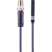
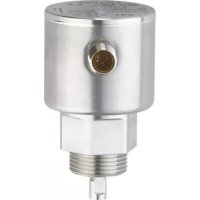
MK5907 - Sound level meters IFM - Free user manual and instructions
Find the device manual for free MK5907 IFM in PDF.


User questions about MK5907 IFM
0 question about this device. Answer the ones you know or ask your own.
Ask a new question about this device
Download the instructions for your Sound level meters in PDF format for free! Find your manual MK5907 - IFM and take your electronic device back in hand. On this page are published all the documents necessary for the use of your device. MK5907 by IFM.
USER MANUAL MK5907 IFM
Operating instructions
Cylinder sensor with IO-Link
MK59xx
Contents
1 Preliminary note.... 4
1.1 Symbols used.... 4
2 Safety instructions 5
2.1 Cybersecurity.... 5
3 Transport, handling and storage 6
4 Items supplied 7
5 Intended use 8
5.1 Application area 8
5.2 Restriction of the application area.... 8
6 Function 9
6.1 Measuring principle 9
6.2 Geometric alignment 9
6.3 Signal range.... 10
6.4 Signal direction 10
6.5 Switching signal 11
6.6 Application examples for position monitoring 14
6.6.1 End position with setting aid 14
6.6.2 Detecting two end positions (short-stroke cylinder) 14
6.6.3 Position detection.... 15
6.6.4 Inline material detection 15
6.7 IO-Link 16
7 Installation.... 17
8 Electrical connection 18
9 Operating and display elements.... 19
10 Parameter setting 20
10.1 Output polarity of the switching outputs.... 20
10.2 Switch point logic 20
10.3 Output off.... 21
10.4 Configuring switch points manually.... 21
10.4.1 Parameter setting example: Detecting two end positions 22
10.4.2 Parameter setting example: Inline material detection 23
10.4.2.1 Object monitoring 23
10.4.2.2 Soiling indication 24
10.5 Teach functions.... 25
10.5.1 Switch point teach.... 26
10.5.2 Section Teach.... 27
10.5.2.1 Parameter setting example: Detecting two end positions.... 27
10.5.3 Teach In Application.... 28
10.6 Switching delay 29
10.7 Signal direction 30
10.8 Diagnostics 30
10.8.1 Stroke time monitoring 31
10.8.2 Switching cycle monitoring 32
10.8.3 Magnetic field monitoring 33
10.8.4 Operating hours counter 34
10.8.5 Power cycles.... 34
10.8.6 Internal temperature.... 34
10.9 Resetting the device 34
10.10 Identification 35
10.10.1 Device information 35
10.10.2 Optical localisation 35
11 Operation.... 36
12 Troubleshooting.... 37
13 Maintenance, repair and disposal 39
14 Factory settings.... 40
1 Preliminary note
You will find instructions, technical data, approvals, accessories and further information using the QR code on the device / packaging or at documentation.ifm.com.
1.1 Symbols used
Requirement
Instruction
Reaction, result
bold Designation of keys, buttons or indications
→ Cross-reference without link
→ Cross-reference with link


2 Safety instructions
- The unit described is a subcomponent for integration into a system.
- The system architect is responsible for the safety of the system.
-
The system architect undertakes to perform a risk assessment and to create documentation in accordance with legal and normative requirements to be provided to the operator and user of the system. This documentation must contain all necessary information and safety instructions for the operator, the user and, if applicable, for any service personnel authorised by the architect of the system.
-
Read this document before setting up the product and keep it during the entire service life.
- The product must be suitable for the corresponding applications and environmental conditions without any restrictions.
- Only use the product for its intended purpose (→ Intended use).
- If the operating instructions or the technical data are not adhered to, personal injury and/or damage to property may occur.
- The manufacturer assumes no liability or warranty for any consequences caused by tampering with the product or incorrect use by the operator.
- Installation, electrical connection, set-up, operation and maintenance of the product must be carried out by qualified personnel authorised by the machine operator.
- Protect units and cables against damage.
2.1 Cybersecurity
Installation
The device is suitable for operation in a secure environment according to IEC 62443-1-1.
The device was designed for operation behind a firewall.
▶ Carry out a risk assessment of the system according to IEC 62443-1-1.
▶ Take measures to ensure physical security.
Operation
▶ Observe the security functions described in the product documentation and the recommendations for their use.
Maintenance
- ▶ Back up system configuration and system data in accordance with your company’s change management processes.
Decommissioning
▶ Ensure that no sensitive information can fall into unauthorised hands.
▶ Always reset the system settings to the factory settings before decommissioning the device.
3 Transport, handling and storage
▶ Store the device in its original packaging.
▶ When the device is to be stored again, use the original packaging.
▶ Otherwise, provide unused connections with either a mating connector or a protective cap and pack the device in suitable packaging.
▶ Observe the permissible ambient conditions for the device during storage (→ Technical data).
4 Items supplied
- Cylinder sensor
- Cable clip
- Rubber placeholder

The following are additionally required for installation and operation: hexagon socket 1.5 mm or slotted screwdriver (not included).
5 Intended use
The device continuously monitors the position of a permanent magnet without contact.
The permanent magnet is detected through non-ferromagnetic cylinder housings.
5.1 Application area
The device is used to detect the position of the piston in pneumatic cylinders.
The device detects the ring magnet attached to a piston through a housing wall of non-magnetisable material (aluminium, brass or stainless steel).
Special adapters for mounting on the following cylinder profiles are available as accessories:
• Clean line and tie rod cylinders
• Integrated profile cylinder
- Trapezoidal slot cylinder
5.2 Restriction of the application area
The device is not approved for use in hazardous areas.
Incorrect measurements may be caused by the following environmental conditions:
• Ferromagnetic environment (elements made of iron)
• Alternating electromagnetic fields
- Rotation of magnets can lead to fluctuations in magnetic field strength.
▶ Check the correct function by performing an application test.
6 Function
The device provides the following functions and signals them with a switching signal:
- Position monitoring (monitoring the piston position in pneumatic cylinders):
- End position with setting aid ➕ 14
- Detecting two end positions (short-stroke cylinder) → 14
- Position detection ➕ 15
– Inline material detection ➕ 15
• Diagnostic functions:
- Stroke time monitoring ➕ 31
- Switching cycle monitoring ➕ 32
- Magnetic field monitoring ➕ 33
Depending on the device type, one or two physical switching outputs are available:
| T-slot sensors | Number of switching outputs |
| MK5904, MK5907, MK5908, MK5909 | 2 |
| MK5905, MK5906 | 1 |
6.1 Measuring principle
The device measures the magnetic field in 2 spatial directions ( Bx and By ) and calculates the absolute magnetic field ( Babs ) and a position-dependent signal PDV1.
The absolute magnetic field must be in the range of 1 mT...20 mT.
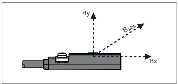
Bx : Magnetic field in x-direction
Bv : Magnetic field in y-direction
Babs : Absolute magnetic field
If the magnetic system is designed accordingly, the calculated output signal is linear and proportional to the position of an encoder magnet.

Ferromagnetic materials (iron), permanent magnets and magnetic fields in the vicinity of the device or the encoder magnet can influence and falsify the signal.
6.2 Geometric alignment
The magnetic axis of the encoder magnet should be parallel to the longitudinal axis of the device and correspond to the direction of movement.

1: Magnetic axis

In the event of magnetisation errors (magnetic axis not parallel to the device) or an offset between the magnetic axis and the sensor plane, the linearity of the output signal PDV1 will be impaired.
6.3 Signal range
The device provides a measured value [PDV1] depending on the position of the encoder magnet in the range of 0...4000. This value is dimensionless, but proportional to the position of the encoder magnet.
On delivery, the output signal corresponds to the value 2000 when the encoder magnet is centred under the target marking “T” on the device. Due to the shape of the encoder magnet and the distance between the device and the magnet, different slopes of the signal curve as well as different resolutions and measuring ranges can be achieved.

The longer a magnet is, the lower the slope of the signal curve and the resolution and the larger the measuring range becomes.

If the magnets are too weak or the distance between the device and the magnet is too great, the signal range may be limited at the edges if the magnetic field is too weak.

If the magnets are too strong or the distance between the device and the magnet is too small, the signal range may be interrupted in the middle if the magnetic field is too strong.
6.4 Signal direction
Depending on the orientation of the magnet, the slope of the signal may vary.
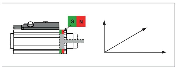
Fig. 1: Piston rod North Pole direction
The signal increases when the piston rod is extended.
The device behaves according to the specified function class “Object Detection”.

Fig. 2: Piston rod South Pole direction
The signal decreases when the piston rod is extended.
▶ Inverting the signal direction.
Inverting the signal
Inverting the signal changes whether the process data value (PDV) increases (1) or decreases (2) when the piston is extended. Changing the signal direction can be useful for the respective application.

Fig. 3: Signal direction. Depending on the type of magnet, the setting can also be reversed.
1: Not inverted
2: Inverted
After changing the signal direction, the process data value changes. ▶ Carry out a new parameter setting of the switching channels.
The orientation of the device when inserted into the groove has no effect on the signal direction.
After an Application Teach, the LEDs for the switch point indication may be reversed. By inverting the signal direction before an Application Teach, the assignment of the LEDs can also be changed.
6.5 Switching signal
The device provides digital switching signals via switching signal channels (SSC = Switching Signal Channel).
The device has two digital switching signal channels SSC1.1 and SSC1.2 which can be used to output the process value.
Explanation of the numbering of the switching signal channels SSCx.y: x = process value; y = switching signal channel
The switching channels can be analysed via the IO-Link interface and the hardware outputs.
The switching channels can be freely assigned to the physical hardware outputs OUT1 and OUT2.
For devices with only one hardware output, the following applies: the switching channels can be freely assigned to the physical hardware output OUT1.
The parameters for each switching signal channel can be set individually.
During parameter setting, the switch points, mode and logic of the switching signal channels are set.
Mode
You can choose between the following modes according to the IO-Link smart sensor profile – Function Class “Object Detection”:
- Deactivated
- Single Point Mode
- Two Point Mode
- Window Mode
The switching channel changes to the active state depending on the process data value (PDV).

The active state is below the switch point in Single Point Mode and Two Point Mode and within the window section in Window Mode.
Logic
By setting the logic High active or Low active, you can specify which value the switching signal channel has in the active state:
- High active: The switching signal channel is "high" in the active state (= ON = normally open = 1)
- Low active: The switching signal channel is "low" in the active state (= OFF = normally closed = 0)
The following figures show the status of the switching signal channels depending on the mode, logic and process data value (PDV).
Deactivated
If the Deactivated mode is set for a switching signal channel, the switching signal channel will permanently have the following value regardless of the process value:
- For logic High active: permanently "low".
- For logic Low active: permanently "high".

Fig. 4: Deactivated / High active

Fig. 5: Deactivated / Low active
Single-point mode
Only one switch point SP1 is manually set or taught.
The reset point SP1+H results from the switch point and the set hysteresis.
When teaching, the switch point is set above the taught process value TP1 by the hysteresis.
The switch point SP2 will be ignored in Single Point Mode.
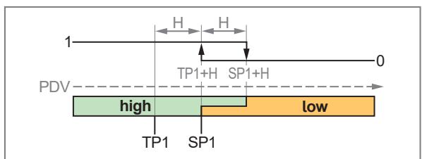
Fig. 6: Single Point Mode / High active
H: Hysteresis
SP1: Switch point
TP1: Teach point
TP1+H: Switch point during teach (= SP1)
SP1+H Reset point

Fig. 7: Single Point Mode / Low active
H: Hysteresis
SP1: Switch point
TP1: Teach point
TP1+H: Switch point during teach (= SP1)
SP1+H Reset point
Two-point mode
A switch point SP1 and a switch point SP2 are manually set or taught.
The position of the switch points is freely selectable: SP1 can be below or above SP2. The higher switch point is the reset point. In the example shown, SP2 is the switch point (setpoint) and SP1 is the reset point.
When teaching, the switch point is set directly to the respective taught process value TPx.
The hysteresis will be ignored in Two Point Mode.
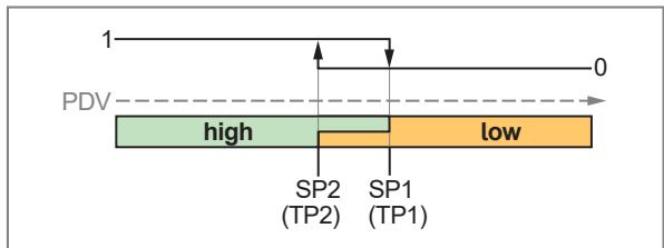
Fig. 8: Two Point Mode / High acitve
SP1: Switch point 1
SP2: Switch point 2
TP1: Teach point 1 (= SP1)
TP2: Teach point 2 (= SP2)
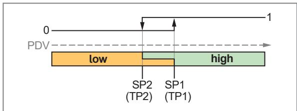
Fig. 9: Two Point Mode / Low active
SP1: Switch point 1
SP2: Switch point 2
TP1: Teach point 1 (= SP1)
TP2: Teach point 2 (= SP2)
Window mode
Two switch points SP1 and SP2 are manually set or taught.
The two switch points define a window area.
The position of the switch points is freely selectable: SP1 can be below or above SP2. The lower switch point is the lower limit value, the higher switch point is the upper limit value of the window area.
When teaching, the switch point is set directly to the respective taught process value TPx.
When the process data value enters the window area, the status of the switching signal channel changes when the switch points are exceeded/not reached.
When the process data value leaves the window area, the status of the switching signal channel changes when the switch point plus/minus the hysteresis is exceeded/not reached.
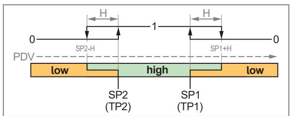
Fig. 10: Window Mode / High active
H: Hysteresis
SP1: Switch point 1
SP2: Switch point 2
TP1: Teach point 1 (= SP1)
TP2: Teach point 2 (= SP2)

Fig. 11: Window Mode / Low active
H: Hysteresis
SP1: Switch point 1
SP2: Switch point 2
TP1: Teach point 1 (= SP1)
TP2: Teach point 2 (= SP2)
6.6 Application examples for position monitoring
6.6.1 End position with setting aid
The setting aid can be used to shut down a device or valve prematurely so that the piston moves more smoothly into the end stop.
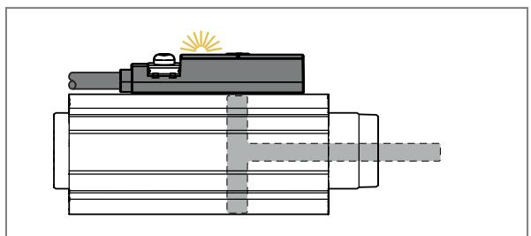
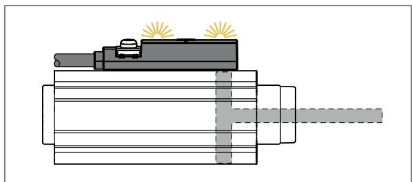
Piston shortly before the end position (e.g. at 80 % of the end position):
- LED 1 is on.
- The output to which SSC1.1 has been assigned switches.
Piston in the end position:
- Both LEDs are on.
- Both outputs switch.
6.6.2 Detecting two end positions (short-stroke cylinder)
If the stroke of the piston does not exceed the measuring range of the device, both end positions can be displayed with one device.

Piston in end position 1:
- LED 1 is on.
- The output to which SSC1.1 has been assigned switches.


- Parameter setting example: Detecting two end positions ➞ 22
- Parameter setting example: Detecting two end positions → 27
6.6.3 Position detection
When using the IO-Link interface, the magnet position can be evaluated exactly via a dimensionless process data value between 0...4000. The process data value is linearly proportional to the magnet position.
Thanks to accurate position detection, process deviations can be monitored, such as the drift of an operation as well as wear and soiling. In this way, quality monitoring can be carried out independently of switch points by the PLC.


1: Process data value PDV1
2: Magnet position
Piston between the end positions.
Accurate position detection through continuous measurement.
6.6.4 Inline material detection
With inline material detection, objects can be detected, compared and counted. This can be done using accurate position detection via IO-Link or the physical switching outputs and the LED display.
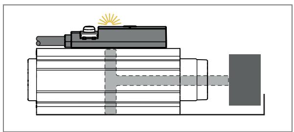
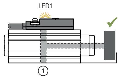
Piston rod detects predefined object.

Piston rod detects no object.

- Parameter setting example: Object monitoring ➕ 23
- Parameter setting example: Soiling indication ➕ 24
6.7 IO-Link
IO-Link is a communication system for connecting intelligent sensors and actuators to automation systems. IO-Link is standardised in the IEC 61131-9 standard.

General information on IO-Link at io-link.ifm

Input Output Device Description (IODD) with all parameters, process data and detailed descriptions of the device at documentation.ifm.com
IO-Link offers the following advantages:
• Interference-free transmission of all data and process values
• Parameter setting in the running process or presetting outside the application
- Parameters for identifying the connected devices in the system
• Additional parameters and diagnostic functions
• Automatic backup and restore of parameter sets in case of device replacement (data storage)
- Logging of parameter sets, process values and events
• Device description file (IODD - Input Output Device Description) for easy project planning
• Standardised electrical connection
- Remote maintenance
7 Installation
The factory setting allows only one end position to be queried without any further parameter setting. In factory setting, the following parameters are set:
• SSC1.1 and SSC1.2: Window Mode, high active, Hysterese = 100
• SSC1.1 window area: 1800 (SP1)... 2200 (SP2)
• SSC1.2 window area: 1900 (SP1)... 2100 (SP2)
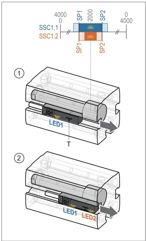
Fig. 12: Installation procedure
▶ Move the piston to the end position to be detected.
▶ Connect the device and insert it into the cylinder groove.
▶ Slide the device in the groove towards the end position until LED1 is on.
▷ The magnet is located in the window area of switching channel SSC1.1.
▶ Slowly slide the device further towards the end position until LED2 is also on.
▷ The magnet is located in the window area of switching channel SSC1.2.
▶ Fix the device in this position using the fastening clamp.

The process data value is now > 1900 or < 2100, depending on the signal direction of the encoder magnet. When the magnet and marking (T) of the device are precisely aligned, the PDV is 2000.

The orientation of the device when inserted into the groove has no effect on whether the process data value increases or decreases when the piston is extended. The signal direction depends on the magnet and can be reversed using the parameter setting software ➕ 10.
8 Electrical connection

The unit must be connected by a qualified electrician.
Observe the national and international regulations for the installation of electrical equipment.
Voltage supply according to SELV, PELV.
▶ Disconnect power.
▶ Connect the unit as follows:


Fig. 13: Wiring diagram
| Pin | Assignment |
| 1 | L+ |
| 3 | L- |
| 4 (OUT1) | Switching output or IO-Link |
| 2 (OUT2) | Switching output, depending on device type ➞ 9 |
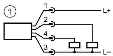

Fig. 14: Circuit examples
1: 2 x positive switching
2: 2 x negative switching
9 Operating and display elements

Fig. 15: Indicators
1: Fastening clamp
2: LED green (ready for operation)
3: Sensing face
LED1: Is yellow if SSC1.1 is active
LED2: Is yellow if SSC1.2 is active
The two LEDs are permanently assigned to the switching channels: LED1 to SSC1.1 and LED2 to SSC1.2.
The yellow light of the LED signals that the switching channel SSC1 is in the "high" state.
- If the switching channel is set to the logic High active, the LED lights up when the switching channel is in the active state.
- If the switching channel is set to the logic Low active, the LED goes out when the switching channel is in the active state.
For switching channels SSC1.1 and SSC1.2, opposite switch-point logic may be useful, for example to display two end positions using different LEDs.

The two yellow switching status LEDs can be set to synchronous double flashing with the command [Locator] in order to be able to identify the device in the installation ➕ 35.

In the event of a short circuit or hardware error in the device, both yellow switching status LEDs will flash until the error is eliminated ➞ 37.
10 Parameter setting
The parameters are set via the IO-Link interface on pin 4 using the parameter setting software.
Parameters can be set before installation or during operation.

If you change parameters during operation, this will influence the function of the plant.
▶ Ensure that there will be no malfunctions in your plant.
During parameter setting the unit remains in the operating mode. It continues to monitor with the existing parameter until the parameter setting has been completed.
The device parameters can be set via the IO-Link interface in the following ways, for example:
- Parameter setting via a suitable parameter setting software, e.g. ifm moneo|configure
• Parameter setting via a PLC
• Parameter setting via an IIoT application
Requirements for parameter setting via the IO-Link interface:
√ The Input Output Device Description (IODD) for the device in case of parameter setting via a parameter setting software, see documentation.ifm.com
√ The IO-Link interface description (PDF) for the device in case of parameter setting via a PLC or IIoT application, see documentation.ifm.com
√ An IO-Link master
▶ Connect the IO-Link master to the parameter setting software, the PLC or the IIoT application.
▶ Connect the device to a suitable free port of the IO-Link master.
▶ Set the port of the IO-Link master to the IO-Link operating mode.
▷ The device changes to the IO-Link mode.
▶ Change the parameter settings in the software.
▶ Write the parameter settings to the device.

Support for system integration and parameter setting via IO-Link:
→ Manual of the parameter setting software (e.g. moneo)
Explanations and startup packages at ifm.com/cnt/io-link-system-integration.

When the pneumatic cylinder is changed, it may also be necessary to adapt the device settings.
10.1 Output polarity of the switching outputs
The parameter P-n can be used to select whether the switching outputs are positive switching or negative switching.
▶ Select Parameters > Basic settings.
▶ Select P-n and set PnP or nPn.
10.2 Switch point logic
The switch point logic of the switching outputs can be set.
Selectable values:
• High active = normally open
- Low active = normally closed
▶ Select Parameter > SSC1.x.
▶ Select SSC1.x Config. Logic and set the switch point logic for the switching signal channel SSC1.x.
10.3 Output off
The output signal for output OUT1 or output OUT2 can be switched off in two ways:
- OFF: The physical output OUTx becomes highly resistive so that no signal can be output. The status of the switching signal channels SSC1.x is still transmitted via the IO-Link interface.
- Deactivated: The switching signal channel is deactivated, i.e. the switching state is permanently in the inactive state: With High active setting permanently "low", with Low active setting permanently "high".
▶ Call up Parameters > Output Configuration.
▶ Select oux and set OFF. - or -
▶ Select Parameter > SSC1.x.
▶ Select SSC1.x Config. Mode and set Deactivated.
10.4 Configuring switch points manually
During configuration, set the switch point mode before defining the other parameters such as switch points and hysteresis.
▶ Select Parameter > Output configuration > oux and set the switching signal channel for output OUTx: SSC1.1 or SSC1.2.
▶ Select Parameter > SSC1.x.
Single point mode:
▶ Select SSC1.x Config. Mode and set the Single Point mode.
▶ Select SSC1.x Param. SP1 and set switch point 1.
▶ Select SSC1.x Config. Hyst and set the hysteresis.
Two-point mode:
▶ Select SSC1.x Config. Mode and set the Two Point mode.
▶ Select SSC1.x Param. SP1 and set switch point 1.
▶ Select SSC1.x Param. SP2 and set switch point 2.
Window mode:
▶ Select SSC1.x Config. Mode and set the Window mode.
▶ Select SSC1.x Param. SP1 and set switch point 1.
▶ Select SSC1.x Param. SP2 and set switch point 2.
▶ Select SSC1.x Config. Hyst and set the hysteresis.
Write the changed parameter settings to the device.

▷ The switch points SP1 and SP2 must have a minimum distance to the limits of the measuring range (0 and 4000) in the size of the hysteresis. This restriction applies to each mode, so that it is possible to switch between the switch point modes.

If the hysteresis is set to 0, the device adopts the Auto setting. This setting corresponds to a hysteresis value of 100.
10.4.1 Parameter setting example: Detecting two end positions
In this example, the manual switch point setting is used to configure the device for detecting two end positions in a short-stroke cylinder.
• SSC1.1 (LED1) indicates end position 1.
• SSC1.2 (LED2) indicates end position 2.

In this example, the north pole of the magnet is oriented towards the piston rod, therefore the signal increases when the piston rod is extended and corresponds to the specified Function Class “Object Detection” ➕ 10.
Manual switch point configuration (2x single point mode):

Fig. 16: Detecting two end positions
1: Piston in end position 1 (piston in): LED1 is on. SSC1.1 is active.
2: Piston in end position 2 (piston out): LED2 is on. SSC1.2 is active.
T: Tolerance
H: Hysteresis
Parameter setting:
▶ Install the device in the groove.
▶ Select SSC1.1 Config. Mode and SSC1.2 Config. Mode and set the switch point mode for both: Single Point.
▶ Select SSC1.1 Config. Hyst and SSC1.2 Config. Hyst and set the hysteresis to 100 for both.
▶ Select SSC1.1 Config. Logic and set Low active.
▶ Select SSC1.2 Config. Logic and set High active.
▶ Retract the piston to end position 1 and read the current process data value (PDV) (3000 in the example).
▶ Manually set the switch point SP1 for switching channel SSC1.1: SSC1.1 Param. SP1 = 3000 (PDV) - 100 (tolerance) - 100 (hysteresis) = 2800.
▶ Retract the piston to end position 2 and read the current process data value (PDV) (500 in the example).
▶ Manually set the switch point SP1 for switching channel SSC1.2:
SSC1.1 Param. SP1 = 500 (PDV) + 100 (hysteresis) = 600.
▶ Save the changed parameter settings on the device.

When calculating the switch points, the tolerance in the amount of the hysteresis is used to ensure that the two end positions are reliably indicated by the light of the LEDs.
10.4.2 Parameter setting example: Inline material detection
10.4.2.1 Object monitoring
When operating in Window Mode, objects can be detected, compared and counted.
In this application example, the device is installed in a cylinder that clamps 2 sheets together for welding.
The device detects whether the correct number of sheets has been inserted. The switching channels control the process via their output signals by means of the switch-point logic set in opposite directions:
• SSC1.1 (LED1) indicates correct clamping and releases the welding process.
• SSC1.2 (LED2) indicates errors and stops the welding process.

In this example, the north pole of the magnet is oriented towards the piston rod, therefore the signal increases when the piston rod is extended and corresponds to the specified Function Class "Object Detection" ➕ 10.
Manual switch point configuration (2x window mode):
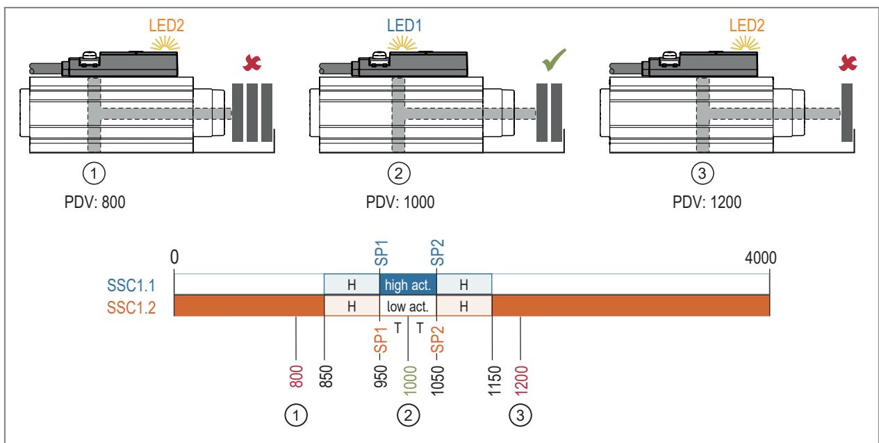
1: End position 3 (3 sheets; PDV: 800)
2: End position 2 (2 sheets; PDV: 1000)
3: End position 1 (1 sheet; PDV: 1200)
Parameter setting:
▶ Install the device in the groove.
▶ Select SSC1.1 Config. Mode and SSC1.2 Config. Mode and set the switch point mode for both: Window.
▶ Select SSC1.1 Config. Hyst and SSC1.2 Config. Hyst and set the hysteresis to 100 for both.
▶ Select SSC1.1 Config. Logic and set High active.
▶ Select SSC1.2 Config. Logic and set Low active.
▶ Insert 2 sheets, extend the piston for clamping and read the current process data value (PDV) (1000 in the example).
▶ Manually set the switch points SP1 and SP2 for both switching channels to the same value: *
▶ Set the parameters SSC1.1 Switch-on delay, SSC1.1 Switch-off delay, SSC1.2 Switch-on delay and SSC1.2 Switch-off delay all to 25 ms.**
▶ Save the changed parameter settings on the device.
SSC1.1 Param. SP1 = SSC1.2 Param. SP1 = 1000 (PDV) - 50 (tolerance) = 950.
SSC1.1 Param. SP2 = SSC2.2 Param. SP2 = 1000 (PDV) + 50 (tolerance) = 1050.

* The value to be selected for tolerance and hysteresis depends on the sheet thickness and object size.
** The settings are used to suppress magnetic interference fields. No false switching pulses occur during welding.
10.4.2.2 Soiling indication
In this application example, the device is installed in a cylinder that clamps a workpiece to be machined. Due to abrasion and chips, the clamping device must be cleaned regularly.
The switching channels show the following:
• SSC1.1 (LED1) shows a correctly clamped workpiece.
- SSC1.1 (LED1) and SSC1.2 (LED2) together indicate tolerable soiling and a warning is issued.
- SSC1.2 (LED2) indicates intolerable soiling of the clamping device.

In this example, the north pole of the magnet is oriented towards the piston rod, therefore the signal increases when the piston rod is extended and corresponds to the specified Function Class “Object Detection” ➕ 10.
Manual switch point configuration (Single Point / Window):
PDV: 3000

PDV: 2800

PDV: 2600

Fig. 17: Soiling indication
1: No soiling: LED1 is on. SSC1.1 is active.
2: Tolerable soiling: LED1 and LED2 are on. SSC1.1 and SSC1.2 are active.
3: Heavily soiled: LED2 is on. SSC1.2 is active.
Parameter setting:
▶ Install the device in the groove.
▶ Select SSC1.1 Config. Hyst and SSC1.2 Config. Hyst and set the hysteresis to 100 for both.
▶ Place the workpiece in the clean fixture, extend the piston for clamping and read the current process data value (PDV) (3000 in the example).
▶ Select SSC1.1 Config. Mode and set the switch-point mode: Single Point.
▶ Manually set the switch point SP1 for switching channel SSC1.1: SSC1.1 Param. SP1 = 3000 (PDV) - 200 (tolerance) - 100 (hysteresis) = 2700.*
▶ Select SSC1.1 Config. Logic and set Low active.
▶ Retract the piston completely and read the current process data value (PDV) (1000 in the example).
▶ Select SSC1.2 Config. Mode and set the switch-point mode: Window.
▶ Manually set the switch points SP1 and SP2 for switching channel SSC1.2: *
SSC1.2 Param. SP1 = 3000 (PDV) - 100 ( 1/2 tolerance) - 100 (hysteresis) = 2800.
SSC1.2 Param. SP2 = 1000 (PDV) + 100 ( 1/2 tolerance) + 100 (hysteresis) = 1200.
▶ Select SSC1.2 Config. Logic and set High active.
▶ Save the changed parameter settings on the device.

* The value to be selected for tolerance and hysteresis depends on the workpiece and the tolerable soiling.
10.5 Teach functions
The three teach functions can be used to teach switch points for the switching channels SSC1.1 and SSC1.2 based on the current magnet position.
The application teach also allows automatic parameter setting of the stroke time monitoring ➞ 31.
10.5.1 Switch point teach
In case of the switch point teach Teach SPx, the switch points are taught individually for the selected switching channel SSC1.x on the basis of the current magnet position. The switch point mode can be freely selected.
In Single Point mode, the current measured value plus the set hysteresis is adopted as switch point SP1, so that the switch point has a reserve when the piston is fully in the end position:
- SP1 = current measured value + hysteresis ➞ 13
In Window mode and in Two Point mode, the switch point SPx is set exactly to the current measured value:
• SP1 = current measured value at end position 1
• SP2 = current measured value at end position 2

The position of the switch points is freely selectable: SP1 can be below or above SP2. The lower switch point is the lower limit value, the higher switch point is the upper limit value of the window area → 13.
Parameter setting:
▶ Install the device in the groove.
▶ Select the required switching channel SSC1.x as output configuration for oux.
Single point mode:
▶ Select SSC1.x Config. Mode and set the Single Point mode.
▶ Select SSC1.x Config. Hyst and set the hysteresis.
▶ Select the switching channel SSC1.x to be taught under Teach Single Value at parameter TI Select.

If TI Select = all SSC is selected, the teach is carried out for both switching channels simultaneously.
▶ Save the changed parameter settings on the device.
▶ Move the piston to the required position.
▶ Ensure that the current measured value is between 80 ... 3920.
▶ Execute the command: Teach SP1.
▷ The current value plus hysteresis is adopted as switch point SP1.
Window and Two Point Mode:
▶ Select SSC1.x Config. Mode and set the switch-point mode: Two Point or Window.
▶ Select SSC1.x Config. Hyst and set the hysteresis.
▶ Select the switching channel SSC1.x to be taught under Teach Single Value at parameter TI Select.

If TI Select = all SSC is selected, the teach is carried out for both switching channels simultaneously.
▶ Save the changed parameter settings on the device.
▶ Move the piston to the required end position 1.
▶ Ensure that the current measured value is between 80 ... 3920.
▶ Execute command: Teach SP1.
▷ The current value is adopted as switch point SP1.
▶ Move the piston to the required end position 2.
▶ Ensure that the current measured value is between 80 ... 3920.
▶ Execute command: Teach SP2.
▷ The current value is adopted as switch point SP2.
10.5.2 Section Teach
During Section Teach, both switch points for the selected switching channel SSC1.x are taught using the current magnet position and the switch point mode is automatically set to Window.
▷ The switch points SP1 and SP2 are calculated with the current measured value and the set hysteresis:
- SP1 = current measured value - hysteresis.
- SP2 = current measured value + hysteresis.
Parameter setting:
▶ Install the device in the groove.
▶ Select the required switching channel SSC1.x as output configuration for oux.
▶ Select SSC1.x Config. Hyst and set the hysteresis.

The SSC1.x Config. Hyst parameter is only visible if the Single Point or Window setting is selected under SSC1.x Config. Mode.
▶ Select the switching channel SSC1.x to be taught under Teach Single Value at parameter TI Select.

If TI Select = all SSC is selected, the teach is carried out for both switching channels simultaneously.
▶ Save the changed parameter settings on the device.
▶ Move the piston to the required position.
▶ Ensure that the current measured value is between 80 ... 3920.
▶ Select Teach Custom and execute the command: Section Teach.
▷ The switch points SP1 and SP2 are set for the selected switching channel, the switch point mode is Window.
10.5.2.1 Parameter setting example: Detecting two end positions
In this example, the section teach is used to configure the device for detecting two end positions in a short-stroke cylinder.
• SSC1.1 (LED1) indicates end position 1.
• SSC1.2 (LED2) indicates end position 2.
Section Teach (2x Window Mode):
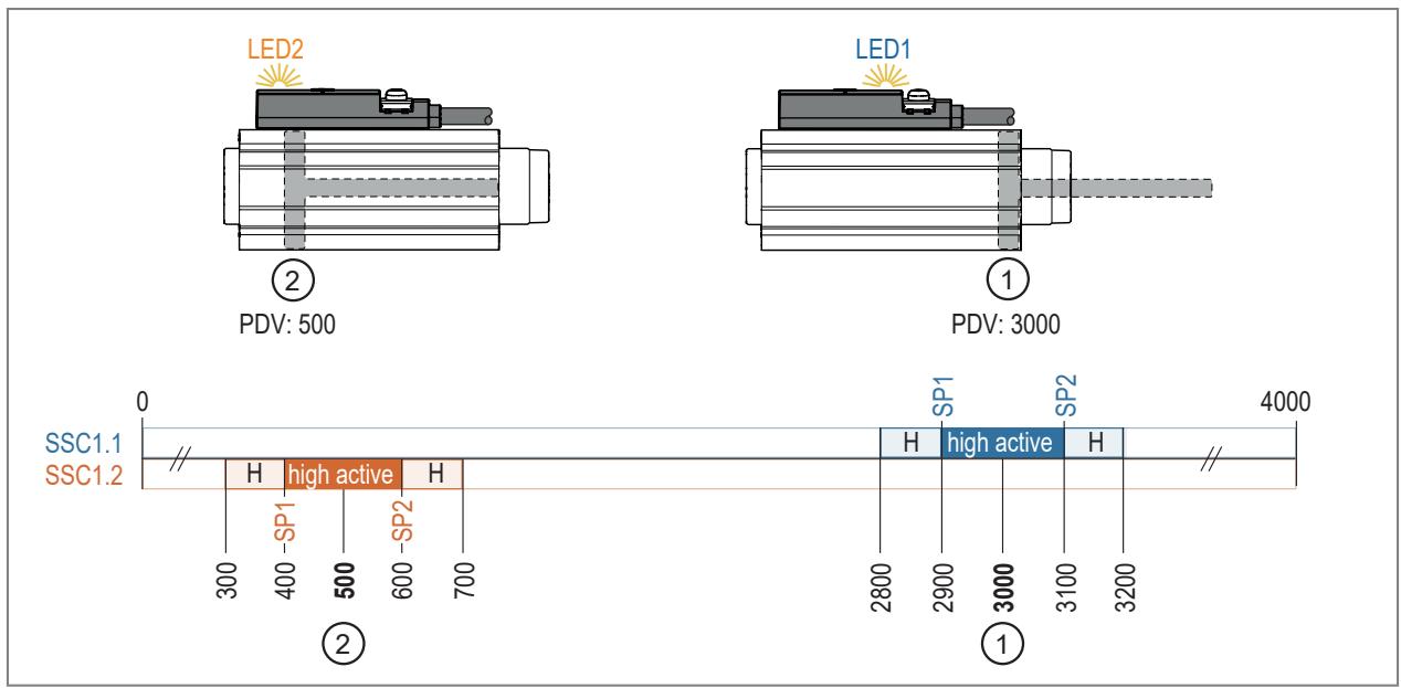
1: End position 1 (PDV: 3000)
2: End position 2 (PDV: 500)
Parameter setting:
▶ Install the device in the groove.
▶ Select SSC1.1 Config. Hyst and SSC1.2 Config. Hyst and set the hysteresis to 100.
▶ Select SSC1.1 Config. Logic and SSC1.2 Config. Logic and set High active.
▶ Move the piston to the required end position 1.
▶ Select the switching channel SSC1.1 for the parameter TI Select under Teach Single Value.
▶ Save the changed parameter settings on the device.
▶ Select Teach Custom and execute the command: Section Teach.
The switch points SP1 and SP2 are set for the selected switching channel, the switch point mode is Window.
▶ Move the piston to the required end position 2.
▶ Select the switching channel SSC1.2 for the parameter TI Select under Teach Single Value.
▶ Save the changed parameter settings on the device.
▶ Select Teach Custom and execute the command: Section Teach.
The switch points SP1 and SP2 are set for the selected switching channel, the switch point mode is Window.
10.5.3 Teach In Application
During Application Teach, the switch point SP1 is automatically determined for the selected switching channel SSC1.x: after moving the magnet back and forth three times, the device detects the minimum and maximum measured value and thereby interprets the two end positions.

The minimum measured value and the maximum measured value must be at least twice the value of hysteresis SSC1.1 and hysteresis SSC1.2 apart:
PDVmax - PDVmin ≥ (2x SSC1.1 Config. Hyst + 2x SSC1.2 Config. Hyst).
Parameter setting:

▶ Install the device in the groove.
▶ Select the required switching channel SSC1.x as output configuration for oux.
▶ Select SSC1.x Config. Hyst and set the hysteresis.

The SSC1.x Config. Hyst parameter is only visible if the Single Point or Window setting is selected under SSC1.x Config. Mode.
▶ Select the switching channel SSC1.x to be taught under Teach Single Value at parameter TI Select.

If TI Select = all SSC is selected, the teach is carried out for both switching channels simultaneously.
▶ Save the changed parameter settings on the device.
▶ Position the piston approximately in the centre beneath the device.
▶ Ensure that the current travel range of the piston is within the limits of the measuring range.
▶ Select Teach Custom and execute the command: Applikations Teach.
▶ Move the piston back and forth between the end positions (min/max). The end positions must be reached alternately three times each.
▷ TI Result. State shows the status of the teach process.
▷ The switch point SP1 is set for the selected switching channel, the switch point mode is Single Point and other parameters are set automatically (see above).

If SSC1.1 is taught, only the minimum end position will be monitored.
If SSC1.2 is taught, only the maximum end position will be monitored.
If both switching channels are taught, both end positions will be monitored by opposite switching behaviour and the display of both LEDs.

If the LEDs do not match the position of the piston after teaching, the signal direction must be inverted before teaching → 10.

To increase the switching areas for the end positions, there are the following possibilities:
▶ Increase the hysteresis before teaching or manually shift the switch points after teaching ➕ 21. In both cases, the automatically set times Reference actuator runtime and Tolerance actuator runtime are no longer correct and must be re-configured. See Stroke time monitoring parameter setting ➕ 31.
10.6 Switching delay
For both switching signal channels, a separate delay time can be set for the output to switch and to be reset.
A switching delay can be useful in the following cases:
- The switch-on and switch-off delay can be used as a filter, for example, to block out magnetic interference fields caused by short-time high currents.
- The switch-off delay can be used as a signal extension.
- With a switch-on delay, a signal can be faded out if the corresponding area is only passed over. The signal will only be output when the application comes to a standstill in the corresponding area or after a corresponding time.

Use in welding applications: To suppress interference from high AC welding currents, the switch-on and switch-off delay must be set to a value greater than 20 ms.
Parameter setting:
▶ Select Parameter > SSC1.x.
▶ Select SSC1.x Switch-On delay and set the time for the switch-on delay.
▶ Select SSC1.x Switch-Off dela and set the time for the switch-off delay.
10.7 Signal direction
The direction of the output measured signal can be inverted ➞ 10.
▶ Select Parameter > Signal > Signal direction to set the signal direction.
10.8 Diagnostics
The device provides the following diagnostic information via the IO-Link interface:
• Operating hours counter → 34
• Power cycles ➞ 34
• Internal temperature ➕ 34
• Stroke time monitoring ➕ 31
• Switching cycle monitoring ➞ 32
• Magnetic field monitoring ➕ 33
In addition, diagnostic messages can be output as switching signals via the hardware outputs OUT1 and OUT2. The switching output set for the diagnostic message is switched on in normal operation (normally closed). If the device detects a diagnostic case, the output will be switched off. The switch point logic cannot be changed.
Diagnostic cases are:
- Timeout 1 → 2 ➞ 31:
The tolerated time window between the activation of SSC1.1 and the activation of SSC1.2 has been exceeded or not reached. - Timeout 2 → 1 ➕ 31:
The tolerated time window between the activation of SSC1.2 and the activation of SSC1.1 was exceeded or not reached.
• Overflow SCT1.1 ➕ 32:
The threshold value for the switching cycles counter SCT1.1 has been reached.
• Overflow SCT1.2 ➕ 32:
The threshold value for the switching cycles counter SCT1.2 has been reached. - NoData → 33:
The magnetic field is too strong or too weak or the magnet is outside the measuring range.
10.8.1 Stroke time monitoring
The stroke time monitoring function monitors the time required by the lifting cylinder to change between two end positions. The two positions (end position 1 and end position 2) are each signalled by a switching signal via the switching signal channels SSC1.1 and SSC1.2.
If more or less time is needed for the position change than set via a tolerance time, the "Timeout" event will be activated.
Stroke time monitoring can be used, for example, to detect wear on the cylinder, dirt in the application or low air pressure.
10.8.1.1 Stroke time monitoring parameter setting
The time for changing a piston rod between two end positions can be monitored in both directions of movement of the lifting cylinder. For this purpose, the sequence of the switching process must be observed when selecting the parameters:
1 --> 2: Time between deactivation of SSC1.1 and activation of SSC1.2
2 --> 1: Time between deactivation of SSC1.2 and activation of SSC1.1
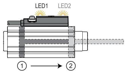
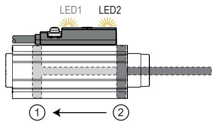
Fig. 18: Stroke time monitoring when changing end positions 1 --> 2 or when changing end positions 2 --> 1.
| Parameter | Explanation | |
| (A) | Current actuator runtime 1 --> 2 Current actuator runtime 2 --> 1 | Actual time required for the change between both end positions. The value can only be read. |
| (B) | Reference actuator runtime 1 --> 2 Reference actuator runtime 2 --> 1 | Required time for the change between both end positions. |
| (C) | Tolerance actuator runtime 1 --> 2 Tolerance actuator runtime 2 --> 1 | Tolerated difference between (A) and (B). |
Tab. 1: Parameters for stroke time monitoring
Example:
Reference actuator runtime 1 --> 2: 1000 ms
Tolerance actuator runtime 1 --> 2: 400 ms
If the Current actuator runtime 1 --> 2 is less than 600 ms, the event “Actuator runtime not reached” will be activated.
If the Current actuator runtime 1 --> 2 is more than 1400 ms, the event “Actuator runtime exceeded” will be activated.

Setting range of the tolerance actuator runtime: 20...20 000 ms. Values outside the setting range will be automatically corrected to the minimum or maximum value during application teach.
Manual parameter setting:
▶ Parameter setting of switching channels SSC1.1 and SSC1.2.
▶ Call up Parameters > Output Configuration.
▶ Select oux and set the diagnostic function for output OUTx: dOU / diagnostic output.
▶ Select dFUx and set TimeoutOn / Timeout 1 --> 2 or Timeout
Off / Timeout 2 --> 1.
▶ Select Parameter > Signal.
▶ Select and set the Reference actuator runtime x --> y.
-or-
Execute the command: apply Reference actuator runtime x --> y to adopt the value of the last stroke time.
▶ Select and set the Tolerance actuator runtime x --> y.
▶ Save the changed parameter settings on the device.
Parameter setting via teach:
▶ Performing application teach ➕ 28:
▷ The device recognises minimum and maximum values as end positions after the piston rod has been moved in and out three times and independently sets the switch points for SSC1.1 and SSC1.2 with the mode Single Point.
▷ The average runtime for the piston rod moving in and out is taken as the Reference actuator runtime x --> y.
▷ The tolerance time is set automatically:
Tolerance actuator runtime x --> y = 50 % of Current actuator runtime x --> y.
10.8.2 Switching cycle monitoring
The device stores the number of switching cycles on the switching signal channels SSC1.1 (counter SCT1.1) and SSC1.2 (counter SCT1.2). Depending on the set counting condition, individual switching edges or piston strokes (two switching edges) will be counted.
The counter value can be read via the IO-Link interface.
If the hardware output is used for diagnostics, the switching state changes when a set switching cycle threshold is reached. When using the IO-Link interface, a data bit is set. The change of state applies for a defined hold time or until the counter is reset.
10.8.2.1 Configuring counters
The switching cycle counters SCT1.1 and SCT1.2 are configured separately. A counter with all its parameter settings is assigned to the hardware output via the output configuration.
| Parameter | Explanation |
| ▶ SSC-EnhCtr_HoldTime. SSC1.1SSC-EnhCtr_HoldTime. SSC1.2 | Hold time:duration of the changed switching status when reaching the switching cycle threshold in milliseconds. Requirement:▶ SSC-EnhCtr_AutoReload. SSC1.x = On. |
| SSC-EnhCtr_AutoReload. SSC1.1SSC-EnhCtr_AutoReload. SSC1.2 | Counter reset:OFF: The output switches when the switching cycle threshold is reached. The counter continues counting until it is reset: Reset counter to zero ➞ 33. On: The output switches when the switching cycle threshold is reached. The switching status remains active for the set hold timeSSC-EnhCrt_HoldTime. SSC1.x. Afterwards, the switching output and the counter are reset. The counter starts again at 0. |
| ▶ SSC-EnhCtr_Count Condition. SSC1.1SSC-EnhCtr_Count Condition. SSC1.2 | Count condition:Rising: The counter only adds up switching cycles when changing from low to high (0 ➞ 1). Falling: The counter only adds up switching cycles when changing from high to low (1 ➞ 0). Both: The counter adds up the switching cycles on both edges. ▶ Observe the switch point logic ➞ 20. |
| SSC-EnhCtr_Threshold. SSC1.1SSC-EnhCtr_Threshold. SSC1.2 | Switching cycle threshold:Number of switching cycles at counter SCT1.x at which a switching signal is triggered or the SCT1.x bit is set. |
Tab. 2: Parameters for switching cycle monitoring
Parameter setting:
▶ Call up Parameters > Output Configuration.
▶ Select oux and set the diagnostic function for output OUTx: dOU / diagnostic output.
▶ Select dFUx and select the counter for the diagnostic output: Overflow SCT1.1 or Overflow SCT1.2.
▶ Select Parameters > Counter configuration.
▶ SSC-EnhCtr_HoldTime. SSC1.x and set the hold time for counter SCT1.x.
▶ SSC-EnhCtr_AutoReload. SSC1.x and set counter reset for counter SCT1.x.
▶ SSC-EnhCtr_Count
Condition. SSC1.x and set the counting condition for counter SCT1.x.
▶ Select SSC-EnhCtr_Threshold. SSC1.x and set the switching cycle threshold for counter SCT1.x.
10.8.2.2 Read counter values
▶ Select Parameters > Counter configuration.
▶ Select SSC-EnhCtr. SSC1.1 and read the current value for counter SCT1.1.
▶ Select SSC-EnhCtr. SSC1.2 and read the current value for counter SCT1.2.
10.8.2.3 Reset counters
Reset both counters:
▶ Select Parameters > Counter configuration.
▶ Execute command: Reset counter to zero.
▷ Both switching cycles counters are set to 0.
Reset counters individually:
▶ Select Parameters > Counter configuration.
▶ Execute command: Reset SCT1.x counter.
▷ The switching cycles counter SCT1.x is set to 0.
10.8.3 Magnetic field monitoring
The device measures the magnetic field strength and provides this value via the IO-Link interface. The magnetic field must be in the range 1 mT < Babs < 20 mT ➞ 9.
When using the diagnostic output, the device can output a switching signal as soon as the magnetic field strength is outside the valid range.
▶ Read the current magnetic field strength: Parameter > Signal.
10.8.3.1 Configuring magnetic field monitoring
▶ Call up Parameters > Output Configuration.
▶ Select oux and set the diagnostic function for output OUTx: dOU / diagnostic output.
▶ dFUx and set the trigger for the switching signal: NoData / No data
10.8.4 Operating hours counter
The operating hours since the first set-up are stored by the unit.
The operating hours counter is stored retentively every hour. If the operating voltage is interrupted, the time since the last full hour will be lost.
The maximum counter reading of 2,000,000 h will be retained when it has been reached (no overflow).
The current value can be read via the IO-Link interface.
▶ Select Diagnosis.
▶ Select Operating hours and read value.
10.8.5 Power cycles
The device stores the switch-on operations since the first set-up.
The maximum counter reading of 2,000,000 will be retained when it has been reached (no overflow).
▶ Select Diagnosis.
▶ Select Power cycles and read value.
10.8.6 Internal temperature
The sensor measures the internal temperature.
The internal temperature may be higher than the actual temperature due to self-heating of the processor.
Due to the installation in the cylinder groove, the temperature of the device is strongly coupled to the temperature of the cylinder housing. If the cylinder becomes excessively warm due to wear or overload, this trend can be detected with the device.
▶ Select Diagnosis > Temperature.
▶ Select Internal temperature and read value.
10.9 Resetting the device
The unit can be reset in 2 ways:
- Application Reset: reset of the parameter settings. The following is reset:
– All changed application-specific parameters and teaches.
- Back-to-box: reset to factory settings. The following is reset:
– All changed application-specific parameters and teaches.
- All writeable unit identification parameters such as Application Specific Tag, Function Tag or Location Tag.
– Diagnostic parameters, status parameters, events.

After the back-to-box reset, the device suspends communication and measurement operation until the voltage is interrupted. The IO-Link data storage is not triggered.

We recommend documenting your own settings in the chapter Factory setting before carrying out a reset.
Parameter setting:
▶ Select Parameters > Basic settings.
▶ Execute command: Application reset or Back-to-Box.
▶ Disconnect and reconnect the power supply.
▷ The device carries out a reboot.
10.10 Identification
10.10.1 Device information
Unalterable device information is stored on the unit. This includes:
- Product name
- Product family
- Manufacturer
- Manufacturer ID
- Device ID
- Serial number
- Description
• Hardware / firmware revision
In addition, further freely definable tags with a maximum length of 32 characters can be assigned to the unit via the IO-Link interface using suitable parameter setting software. This includes:
- application-specific tag
- function tag
- location tag
Read/edit device information:
▶ Select Identification.
▶ Read device information or edit editable parameters.
10.10.2 Optical localisation
The device can be located remotely in the system via the IO-Link interface.
When using the command, both switching status LEDs will flash yellow.
▶ Select Identification.
▶ Execute command: Locator Start.
▶ To end the flashing process: Execute command: Locator Stop.
11 Operation
After power-on and the required parameter setting the device is in the operating mode. It carries out its measurement and evaluation functions and generates output signals according to the set parameters.
▶ Check whether the device operates correctly.
12 Troubleshooting
| Display / problem | Cause / remedy |
| Both yellow switching status LEDs flash alternately at 5 Hz | Hardware fault or electronic fault in the device.► Restart the device.► ▶ If the condition persists, replace the device. |
| Both yellow switching status LEDs flash simultaneously at 5 Hz | Short circuit on output OUT1 and / or OUT21).► Remove the short circuit. |
| One or both switching status LEDs light up yellow although the device is not damped by a magnet. | The device stores the last valid measured value and switches the outputs accordingly. This shows which side of the device the magnet is on, even if the magnetic field becomes too weak.► ▶ Move past the device with a magnet to switch off the LEDs.► ▷ Depending on the setting, the LEDs will be switched on with one polarity of the magnet and switched off with the other polarity. When operating in Window Mode, the LEDs are usually switched off with both polarities. See also Signal direction ➕ 10. |
| The green LED is off. | ► Check voltage supply and wiring. |
| Switching status LEDs are reversed:When the piston is in the right end position, the left switching status LED goes on and vice versa. | The yellow switching status LED on the cable side is always assigned to switching channel 1.► Swap the assignment manually by swapping all parameters that affect the switching behaviour between switching channel 1 and switching channel 2.-or-► ▶ Invert the signal direction before an application teach ➕ 10. |
| Error after switch point teach Teach SPx:The piston is in the end position and a switch point teach has been carried out. When the piston returns to the end position, the device will not switch. | With the switch point teach, the switch point is shifted by the hysteresis to the teach point. Depending on the signal direction, the teach point is outside the operating range.► ▶ Manually reduce the switch point by 2 times the hysteresis.► ▶ Use section teach instead of switch point teach. |
| Error after Application Teach:The application teach was carried out successfully, but only one end position is recognised correctly. The parameters of the other switching channel have not been changed. | Before the application teach, All SSC was not selected under TI Select. If the application teach is successful, only the switching channel selected under TI Select will be configured with the newly determined parameters.► Select Parameter > Teach > Teach Single Value.► Select Parameter > Teach > Teach Custom > TI Select and set All SSC.► ▶ Execute the application teach again. |
| IO-Link event “Block parameter setting error”:The device does not accept the values for configuring a switching channel. | The switch points SP1 and/or SP2 were set to the limits of the measuring range. However, the switch points must be further within the limits of the measuring range by at least the value of the hysteresis.► ▶ Reduce hysteresis.► ▶ Shift the switch points further inwards.► ▶ Move the device in the groove so that the switch points will be further in the middle of the measuring range. |
| IO-Link event “Measured signal disturbed” | Magnetic field too strong or too weak.▸ ▶ Ensure that the magnetic field strength is within the specified range.▸ ▷ Move device to valid area |
1) In the event of a short circuit at OUT2 (only for devices with two outputs), the “Short circuit” event will be provided via the IO-Link interface.
13 Maintenance, repair and disposal
The unit is maintenance-free.
Only the manufacturer is allowed to repair the unit.
▶ In case of return shipment, ensure that the unit is free from soiling, especially from dangerous and toxic substances.
▶ For transport only use appropriate packaging to avoid damage of the unit.
▶ After use, dispose of the unit in an environmentally friendly way in accordance with the applicable national regulations.
14 Factory settings
| Parameter | Factory setting | User settings |
| TI Select | SSC1.1 | |
| SSC1.1 Param. SP1 | 1800 | |
| SSC1.1 Param. SP21) | 2200 | |
| SSC1.1 Config. Logic | High active | |
| SSC1.1 Config. Mode | Window | |
| SSC1.1 Config. Hyst1) | 100 | |
| SSC1.1 Switch-On delay | 0 ms | |
| SSC1.1 Switch-Off delay | 0 ms | |
| SSC1.2 Param. SP1 | 1900 | |
| SSC1.2 Param. SP21) | 2100 | |
| SSC1.2 Config. Logic | High active | |
| SSC1.2 Config. Mode | Window | |
| SSC1.2 Config. Hyst1) | 100 | |
| SSC1.2 Switch-On delay | 0 ms | |
| SSC1.2 Switch-Off delay | 0 ms | |
| Output configuration ou1 | SSC1.1 | |
| Diagnostic output dFU13) | Overflow SCT1.1 | |
| Output configuration ou2 2) | SSC1.2 | |
| Diagnostic output dFU23)2) | Overflow SCT1.2 | |
| SSC-EnhCtr_AutoReload. SSC1.x | OFF | |
| SSC-EnhCtr_HoldTime. SSC1.x | 10000 ms | |
| SSC-EnhCtr_Threshold. SSC1.x | 0 | |
| SSC-EnhCtr_Count Condition. SSC1.x | Rising | |
| Signal direction | Not inverted | |
| Actuator reference runtime 1 --> 2 | 0 ms | |
| Actuator runtime tolerance 1 --> 2 | Deactivated | |
| Actuator reference runtime 2 --> 1 | 0 ms | |
| Actuator runtime tolerance 2 --> 1 | 0 ms |
1) The parameter will only be displayed if other parameters have been set accordingly beforehand.
2) The parameter is only available for devices with 2 outputs ➞ 9.
3) The parameter will be displayed, but the setting will only take effect if oux = dOU has been selected.

- 1 PRELIMINARY NOTE
- 1.1 SYMBOLS USED
- 2 SAFETY INSTRUCTIONS
- 2.1 CYBERSECURITY
- 3 TRANSPORT, HANDLING AND STORAGE
- 4 ITEMS SUPPLIED
- 5 INTENDED USE
- 5.1 APPLICATION AREA
- 5.2 RESTRICTION OF THE APPLICATION AREA
- 6 FUNCTION
- 6.1 MEASURING PRINCIPLE
- 6.2 GEOMETRIC ALIGNMENT
- 6.3 SIGNAL RANGE
- 6.4 SIGNAL DIRECTION
- 6.5 SWITCHING SIGNAL
- 6.6 APPLICATION EXAMPLES FOR POSITION MONITORING
- 6.6.1 END POSITION WITH SETTING AID
- 6.6.2 DETECTING TWO END POSITIONS (SHORT-STROKE CYLINDER)
- 6.6.3 POSITION DETECTION
- 6.6.4 INLINE MATERIAL DETECTION
- 6.7 IO-LINK
- 7 INSTALLATION
- 8 ELECTRICAL CONNECTION
- 9 OPERATING AND DISPLAY ELEMENTS
- 10 PARAMETER SETTING
- 10.1 OUTPUT POLARITY OF THE SWITCHING OUTPUTS
- 10.2 SWITCH POINT LOGIC
- 10.3 OUTPUT OFF
- 10.4 CONFIGURING SWITCH POINTS MANUALLY
- 10.4.1 PARAMETER SETTING EXAMPLE: DETECTING TWO END POSITIONS
- 10.4.2 PARAMETER SETTING EXAMPLE: INLINE MATERIAL DETECTION
- 10.4.2.1 OBJECT MONITORING
- 10.4.2.2 SOILING INDICATION
- 10.5 TEACH FUNCTIONS
- 10.5.1 SWITCH POINT TEACH
- 10.5.2 SECTION TEACH
- 10.5.2.1 PARAMETER SETTING EXAMPLE: DETECTING TWO END POSITIONS
- 10.5.3 TEACH IN APPLICATION
- 10.6 SWITCHING DELAY
- 10.7 SIGNAL DIRECTION
- 10.8 DIAGNOSTICS
- 10.8.1 STROKE TIME MONITORING
- 10.8.2 SWITCHING CYCLE MONITORING
- 10.8.3 MAGNETIC FIELD MONITORING
- 10.8.4 OPERATING HOURS COUNTER
- 10.8.5 POWER CYCLES
- 10.8.6 INTERNAL TEMPERATURE
- 10.9 RESETTING THE DEVICE
- 10.10 IDENTIFICATION
- 10.10.1 DEVICE INFORMATION
- 10.10.2 OPTICAL LOCALISATION
- 11 OPERATION
- 12 TROUBLESHOOTING
- 13 MAINTENANCE, REPAIR AND DISPOSAL
- 14 FACTORY SETTINGS
Brand : IFM
Model : MK5907
Category : Sound level meters