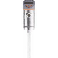
SA4120 - Detector IFM - Free user manual and instructions
Find the device manual for free SA4120 IFM in PDF.


User questions about SA4120 IFM
0 question about this device. Answer the ones you know or ask your own.
Ask a new question about this device
Download the instructions for your Detector in PDF format for free! Find your manual SA4120 - IFM and take your electronic device back in hand. On this page are published all the documents necessary for the use of your device. SA4120 by IFM.
USER MANUAL SA4120 IFM
Operating instructions
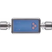
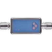
Flow sensor
SAxx20
Contents
1 Preliminary note 4
1.1 Symbols used 4
1.2 Warnings.... 4
2 Safety instructions.... 5
3 Getting started 6
3.1 Device function with factory setting 6
4 Functions and features 7
4.1 Application area 7
5 Function 8
5.1 Output OUT1 selection options 8
5.2 Output OUT2 selection options 8
5.3 Operating modes 8
5.4 Calibration....8
5.5 Switching output 9
5.6 Analogue output 10
5.7 Frequency output 10
5.8 Measured value damping 12
5.9 Display colour setting 12
5.10 IO-Link 12
5.10.1 IO-Link process values 13
6 Installation.... 14
6.1 Process connection.... 14
6.2 Interference.... 14
6.3 Installation position 15
6.3.1 Immersion depth 15
6.3.2 Recommended mounting position.... 15
6.3.3 Conditionally possible installation position.... 15
6.3.4 Impermissible installation position.... 16
6.3.5 Alignment 16
7 Electrical connection.... 17
8 Operating and display elements 18
9 Menu....19
9.1 Menu overview 19
9.2 Main menu and submenus 19
10 Set-up 22
11 Parameter setting 23
11.1 Parameter setting in general 23
11.2 Presetting 23
11.2.1 Process value for OUT2 23
11.2.2 Operating mode 24
11.2.3 Standard unit of measurement for flow 24
11.2.4 Internal pipe diameter 24
11.2.5 Flow adjustment 24
11.2.6 Remote calibration 25
11.3 Setting the output functions.... 25
11.3.1 Limit monitoring OUTx / hysteresis function 25
11.3.2 Limit monitoring OUTx / window function 25
11.3.3 Frequency signal OUTx 26
11.3.4 Analogue signal OUT2 26
11.4 User settings (optional) 26
11.4.1 Standard display 26
11.4.2 Display colour setting 26
11.4.3 Output logic.... 27
11.4.4 Measured value damping 27
11.4.5 Switch-on /switch-off delay 27
11.4.6 Error behaviour of the outputs.... 27
11.4.7 Calibration.... 27
11.4.8 Lock/unlock 28
11.4.9 Factory reset.... 28
11.5 Diagnostic functions 28
11.5.1 Reading minimum values / maximum values.... 28
12 Operation 29
12.1 Process value display 29
12.2 Reading the parameter setting 29
13 Technical data.... 30
14 Troubleshooting 31
14.1 Error messages.... 31
14.2 Warning messages 31
15 Maintenance, repair and disposal 33
16 Factory settings.... 34
1 Preliminary note
You will find instructions, technical data, approvals and further information using the QR code on the unit / packaging or at documentation.ifm.com.
1.1 Symbols used
√ Requirement
Instructions
Reaction, result
[...] Designation of keys, buttons or indications
→ Cross-reference

Important note
Non-compliance may result in malfunction or interference.

Information
Supplementary note
1.2 Warnings
Warnings indicate the possibility of personal injury and damage to property. This enables safe product handling. Warnings are graded as follows:

WARNING
Warning of serious personal injury
▷ If the warning is not observed, fatal and serious injuries are possible.

CAUTION
Warning of minor to moderate personal injury
▷ If the warning is not observed, minor to moderate injuries are possible.
ATTENTION
Warning of damage to property
▷ If the warning is not observed, damage to property is possible.
2 Safety instructions
- The unit described is a subcomponent for integration into a system.
- The system architect is responsible for the safety of the system.
-
The system creator undertakes to perform a risk assessment and to create documentation in accordance with legal and normative requirements to be provided to the operator and user of the system. This documentation must contain all necessary information and safety instructions for the operator, the user and, if applicable, for any service personnel authorised by the architect of the system.
-
Read this document before setting up the product and keep it during the entire service life.
- The product must be suitable for the corresponding applications and environmental conditions without any restrictions.
- Only use the product for its intended purpose (→ Intended use).
- Only use the product for permissible media (→ Technical data).
- If the operating instructions or the technical data are not adhered to, personal injury and/or damage to property may occur.
- The manufacturer assumes no liability or warranty for any consequences caused by tampering with the product or incorrect use by the operator.
- Installation, electrical connection, set-up, operation and maintenance of the product must be carried out by qualified personnel authorised by the machine operator.
- Protect units and cables against damage.
3 Getting started
The unit has two configurable outputs for flow and temperature monitoring.
The process values and error messages can be read from the display.
All process values and messages are available via the IO-Link interface irrespective of the output configuration.
3.1 Device function with factory setting
| Factory setting | |
| Operating mode | Relative flow measurement in % of the maximum flow |
| Output OUT1 | Switching signal for flow:– hysteresis function normally open, PnP– SP1 = 20 %, rP1 = 15 % of the final value of the measuring range Measured value damping 0.6 secondsNo switch-on /switch-off delayIn case of a fault the output switches OFF |
| Output OUT2 | Analogue signal for flow (4...20 mA; measuring range unscaled)In case of a fault the analogue signal goes to 3.5 mA |
| Display | Red text colour Update of the measured values every 200 msStandard display: flow |
More information: Factory setting ( → Factory settings ☐ 34).
4 Functions and features
The unit monitors gaseous media.
It detects the process categories flow and medium temperature.
4.1 Application area
- Medium = air
In applications > 6 bar (> 600 kPa), flow range inaccuracies may occur due to the natural convection of the air.
This is a class A product. This product may cause radio interference in domestic areas. ▶ If required, take appropriate EMC screening measures.
5 Function
- The unit detects flow based on the calorimetric measuring principle.
- As additional process value the unit detects the medium temperature.
• The unit has an IO-Link interface. - The unit displays the current process values.
• The unit has many self-diagnostic options. - The unit generates two output signals according to the parameter setting.
5.1 Output OUT1 selection options
- Switching signal flow
• Frequency signal flow - IO-Link
5.2 Output OUT2 selection options
- Switching signal flow
- Switching signal temperature
- Analogue signal flow
• Analogue signal temperature
• Frequency signal flow
• Frequency signal temperature - Input for external teach signal (remote adjustment)
5.3 Operating modes
The unit provides 2 selectable operating modes for flow measurement:
| Operating mode [ModE] | Display unit |
| REL | % of the taught range |
| GAS | m/s, l/min, m3/h |
The selected operating mode has no effect on the temperature measurement, only absolute values in ° C are indicated.

When [ModE] = GAS is selected:
▶ Define the internal pipe diameter.
▶ If required, calibrate curve of measured values.

When [ModE] = REL is selected:
▶ Carry out flow adjustment.

The parameter settings are saved in the respective operating mode, i.e. when the operating mode is changed, the settings are not lost.
5.4 Calibration
Via the calibration factor [CGA] the sensor can be adjusted to a reference flow in the application.
The customer-specific calibration allows changing the gradient of the curve of measured values. It influences the display and the outputs.
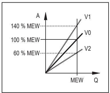
A: Operating value for display and output signals
Q: Flow
MEW: Final value of the measuring range
V: Curve of measured values at factory setting
V1: Curve of measured values 1 after calibration
V2: Curve of measured values 2 after calibration
Fig. 1: Calibration
The change in the gradient is indicated in per cent.
Factory setting: CGA = 100 %.
After a change the calibration can be reset to factory setting.

The parameter CGA is not available if [ModE] = REL is set.

Depending on the set CGA factor, it may not be possible to use the complete measuring range.
5.5 Switching output
OUTx changes its switching status if it is above or below the set switching limits. Hysteresis or window function can be selected.

SP: Set point
rP: Reset point
HY: Hysteresis
Hno: Hysteresis function NO (normally open)
Hnc: Hysteresis function NC (normally closed)
t: Time
Fig. 2: Hysteresis function

When the hysteresis function is set, the set point [SP] and the reset point [rP] are defined. The rP value must be lower than the SP value. The distance between SP and rP is at least 4 % of the final value of the measuring range (= hysteresis). If only the set point is changed, the reset point is changed automatically; the difference remains constant.
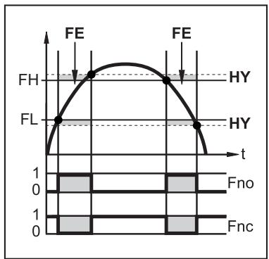
FH: Upper limit value
FL: Lower limit value
HY: Hysteresis
FE: Window
Fno: Window function NO (normally open)
Fnc: Window function NC (normally closed)
t: Time
Fig. 3: Window function

When set to the window function the upper limit value [FH] and the lower limit value [FL] are defined. The distance between FH and FL is at least 4 % of the final value of the measuring range. FH and FL have a fixed hysteresis of 0.25 % of the final value of the measuring range. This keeps the switching status of the output stable if the flow rate varies slightly.
5.6 Analogue output
The unit provides an analogue signal of 4...20 mA proportional to the process value.
The measuring range is scalable:
• [ASP] determines at which measured value the output signal is 4 mA.
• [AEP] determines at which measured value the output signal is 20 mA.

Minimum distance between ASP and AEP = 20 % of the final value of the measuring range.

For flow measurement in the operating mode REL, ASP and AEP are not available. In this operating mode, the characteristic curve of the analogue output is defined by the flow adjustment: high flow = 20 mA; low flow = 4 mA.
If the measured value is outside the measuring range or in the event of an internal error, the current signal indicated in the following figure is provided.
For measured values outside the display range or in case of a fault, messages are displayed (UL, OL, Err).
The analogue signal in case of an error is adjustable ( → Error behaviour of the outputs ☐ 27):
- [FOU] = On: In case of a fault the analogue signal goes to the upper end stop value (22 mA).
- [FOU] = OFF: In case of a fault the analogue signal goes to the lower end stop value (3.5 mA).
• [FOU] = OU: The analogue signal still corresponds to the measured value.

Fig. 4: Characteristics of the analogue output according to the standard IEC 60947-5-7
| 1: | Analogue signal | MAW: | Initial value of the measuring range |
| 2: | Measured value | MEW: | Final value of the measuring range |
| 3: | Display range | ASP: | Analogue start point |
| 4: | Measuring range | AEP: | Analogue end point |
| 5: | Scaled measuring range | UL: | Below the display range |
| Q: | Flow | OL: | Above the display range |
| T: | Temperature | Err: | Error |
5.7 Frequency output
The unit provides a frequency signal proportional to the process value.
The frequency signal is scalable:
- [FrPx] defines the frequency signal in Hz that is provided when the upper measured value (MEW or FEPx) is reached.
The measuring range is scalable:
• [FSP2] defines the lower measured value from which a frequency signal is provided.
– FSP2 is only available for temperature measurement.
- [FEPx] defines the upper measured value at which the output signal has the frequency set under FrPx.
– FEPx is only available for flow measurement in the operating mode GAS.

Minimum difference between FSP2 and FEP2 = 20 % of the final value of the measuring range.
If the measured value is outside the measuring range or in the event of an internal error, the frequency signal indicated in the following figure is provided.
For measured values outside the display range or in case of a fault, messages are displayed (UL, OL, Err).
The frequency signal in case of a fault is adjustable ( → Error behaviour of the outputs ☐ 27):
- [FOU] = On: In case of a fault the frequency signal goes to the upper end stop value (130 % FrPx).
- [FOU] = OFF: In case of a fault the frequency signal goes to the lower end stop value (0 Hz).
- [FOU] = OU: The frequency signal still corresponds to the measured value.

Fig. 5: Output characteristics frequency output; flow
1: Frequency signal
2: Measured value
3: Display range
4: Measuring range
5: Scaled measuring range
MEW: Final value of the measuring range
FEPx: Frequency end point
FrPx: Frequency signal (Hz) for upper measured value
OL: Above the display range
UL: Below the display range
Err: Error

Fig. 6: Output characteristics frequency output; temperature
1: Frequency signal
2: Measured value
3: Display range
4: Measuring range
5: Scaled measuring range
MAW: Initial value of the measuring range
MEW: Final value of the measuring range
FSPx: Frequency start point
FEPx: Frequency end point
FrPx: Frequency signal (Hz) for upper measured value
OL: Above the display range
UL: Below the display range
Err: Error
5.8 Measured value damping
Use the damping time [dAP] to set after how many seconds the output signal has reached 63 % of the final value if the measured value changes suddenly. The set damping time stabilises the switching outputs, the analogue outputs, the display and the process value transmission via the IO-Link interface.
The damping time is added to the response time of the sensor ( → Technical data).
The signals UL and OL are defined under consideration of the damping time.

Measured value damping only has an effect on the measured variable flow.
5.9 Display colour setting
The colour of the characters in the display ( → Display colour setting ☐ 26) can be set via the parameter [coLr]. With the set parameters rED (red) and GrEn (green), the display is permanently set to one colour. If the parameters rxou and Gxou are set, the colour of the characters changes depending on the process value:
| OUT1 | OUT2 | Colour change to... | |
| Parameter setting | r1ou | r2ou | Red |
| G1ou | G2ou | Green |
When the hysteresis function is set, the colour changes if the process value is above the set point:

MAW: Initial value of the measuring range
MEW: Final value of the measuring range
SPx: Set point
Fig. 7: Hysteresis function
When the window function is set, the colour changes if the process value is within the window section:
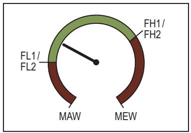
MAW: Initial value of the measuring range
MEW: Final value of the measuring range
FLx: Lower limit of the window section
FHx: Upper limit of the window section
Fig. 8: Window function
5.10 IO-Link
This unit has an IO-Link communication interface which enables direct access to process and diagnostic data. In addition it is possible to set the parameters of the unit while it is in operation. Operation of the unit via the IO-Link interface requires an IO-Link master.
With a PC, suitable IO-Link software and an IO-Link adapter cable, communication is possible while the system is not in operation.
The IODDs necessary for the configuration of the unit, detailed information about process data structure, diagnostic information, parameter addresses and the necessary information about the required IO-Link hardware and software can be found at www.ifm.com.
The IO-Link interface provides the following functions using suitable hardware and software:
- Remote parameter setting of the unit.
- Noise-immune signal transmission without measured value losses.
• Transmission of the parameter settings to a replaced unit or to other units of the same type. - Simultaneous reading of all process values and the binary switching signals.
- Comprehensive display of error and event messages.
- Evaluation of the process values and diagnostic data via IO-Link master.
• Paperless logging of parameter sets, process values and diagnostic information.
• Additional parameters via IO-Link:
– electronic lock as protection against tampering
5.10.1 IO-Link process values
The process values for flow and temperature are transmitted via IO-Link in the following units of measurement:
| Operating mode [ModE] | Flow unit | Temperature unit |
| REL | % | °C |
| GAS | m/s | °C |

A change of [uni] does not affect the IO-Link process values.
More information → IO Device Description at www.ifm.com.
6 Installation

CAUTION
If the medium temperature is above 50\ °C ( 122\ °F ), parts of the housing can increase in temperature to over 65\ °C ( 149\ °F ).
▷ Risk of burns.
▶ Protect the housing against contact with flammable substances and unintentional contact.

▶ Ensure that the system is free of pressure during installation.
▶ Ensure that no media can leak at the mounting location during installation.
6.1 Process connection
Using process adapters the unit can be adapted to different process connections. Adapters have to be ordered separately as accessories.
• Information about the available mounting accessories at www.ifm.com.
- A correct fit of the unit and ingress resistance of the connection are only ensured using ifm adapters.

▶ Observe the instructions of the mounting accessories.

▶ Use a lubricating paste which is suitable and approved for the application. Grease the threads of the process connection, adapter and sensor. Ensure no grease is applied to the sensor tip.

▶ Take the tightening torques of sensor and fixing elements into account: sensor 25 Nm; fixing element → Technical data sheet at www.ifm.com
6.2 Interference
Structures in the pipe, bends, valves, reducing pieces and the like affect the function of the unit.
▶ Adhere to the distances between sensor and interference.

Fig. 9: Inlet and outlet pipe lengths
D: Outside diameter of the pipe
S: Interference
6.3 Installation position
6.3.1 Immersion depth

Fig. 10: Immersion depth
Recommended immersion depths:
- With an internal diameter (diA) < 30 mm of the ventilation pipe / duct: 15 mm.
- With an internal diameter (diA) ≥ 30 mm of the ventilation pipe / duct: middle of the pipe.
6.3.2 Recommended mounting position

Fig. 11: Recommended mounting position
- For horizontal pipes: mounting from the side.
- For vertical pipes: mounting in the rising pipe.

Place the sensor tip as centrally as possible in the pipe. Minimum immersion depth 15 mm.
6.3.3 Conditionally possible installation position

Fig. 12: Conditionally possible installation position
- For horizontal pipes, if the pipe is free from build-up: mounting from below.
- For horizontal pipes, if the pipe is completely filled with medium: mounting from the top.
6.3.4 Impermissible installation position
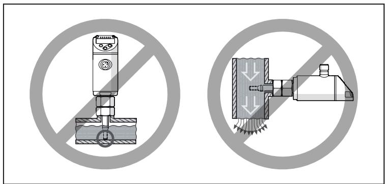
Fig. 13: Impermissible installation position
- The sensor tip must not be in contact with the pipe wall.
- Do not mount in downpipes that are open at the bottom.
6.3.5 Alignment

Fig. 14: Flow direction
▶ To achieve the optimum measuring accuracy, mount the sensor as shown in the figure: Align the spanner flats parallel to the piping; the smaller spanner flat (1) is facing the front if the flow comes from the left.
For easier readability of the display the sensor housing can be rotated by 345° with regard to the process connection.

Do not go beyond the end stop.
7 Electrical connection
The unit must be connected by a qualified electrician.
Observe the national and international regulations for the installation of electrical equipment.
Voltage supply according to SELV, PELV.
▶ Disconnect power.
▶ Connect the unit as follows:

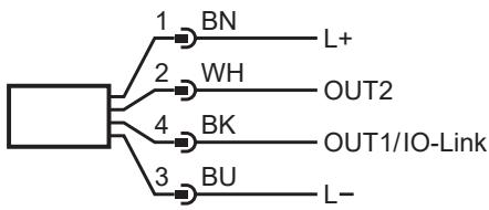
Fig. 15: Wiring diagram (colours to DIN EN 60947-5-2)
BN: Brown
WH: White
BK: Black
BU: Blue
| Pin | Connection |
| 1 | L+ |
| 3 | L- |
| 4 (OUT1) | Switching signal flow Frequency signal flowIO-Link |
| 2 (OUT2) | Switching signal flow Switching signal temperature Analogue signal flow Analogue signal temperature Frequency signal flow Frequency signal temperature Input for external teach signal (remote adjustment) |
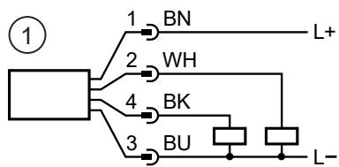
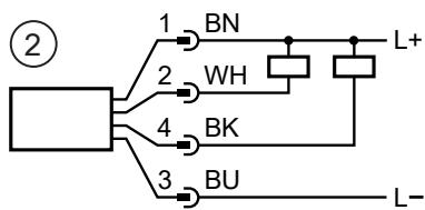
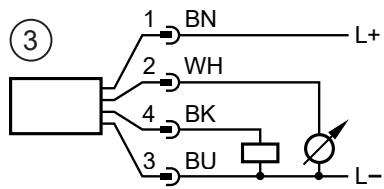
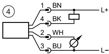
Fig. 16: Circuit examples
1: 2 x positive switching
2: 2 x negative switching
3: 1 x positive switching / 1 x analogue
4: 1 x negative switching / 1 x analogue
8 Operating and display elements
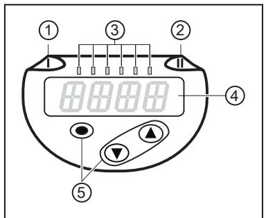
Fig. 17: Operating and display elements
1: Switching status LED for OUT1
2: Switching status LED for OUT2
3: Process value in the indicated unit of measurement (%; m/s; l/min; m3/h ; °C ; x103 )
4: 4-digit alphanumeric display
5: Keys for changing views and parameter setting ( → Parameter setting in general ☐ 23)
9 Menu
9.1 Menu overview
Use the operating keys to navigate from the process value display to the main menu and from there to the submenus. See also Parameter setting in general ( → ☐ 23).
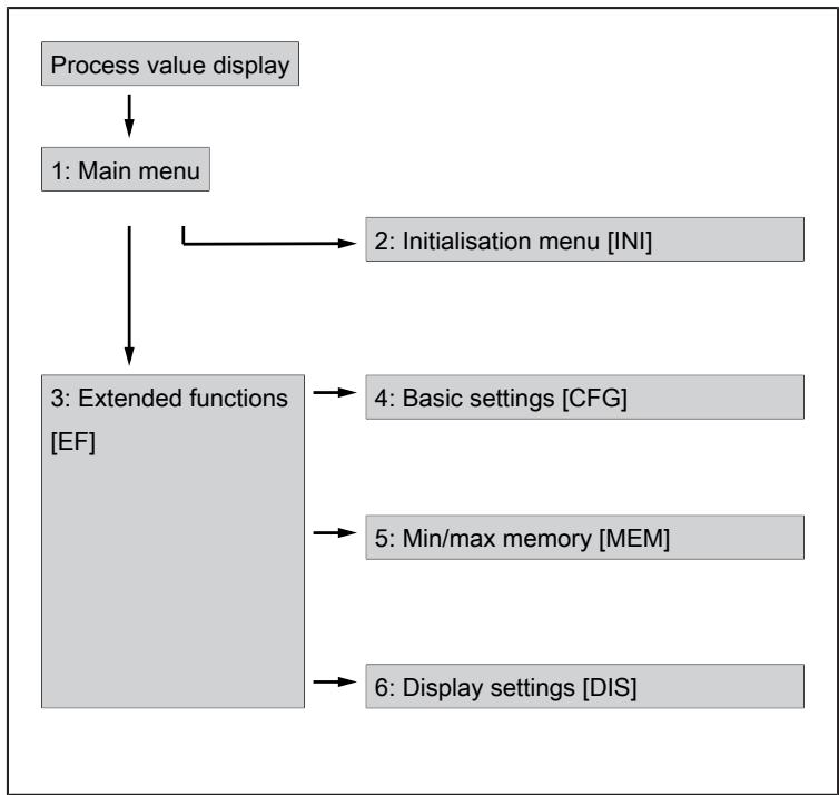
1: Main menu (→ □ 20) 4: Menu Basic settings CFG (→ □ 21)
2: Initialisation menu INI ( → ☐ 20) 5: Menu Min/max memory MEM ( → ☐ 21)
3: Menu Extended functions EF ( → ☐ 20) 6: Menu Display settings DIS ( → ☐ 21)
9.2 Main menu and submenus
The following applies to the menu illustrations below: Parameters with white background are indicated in case of factory setting. If the default settings for the operating mode and output functions are changed, the parameters with a grey background are also visible.
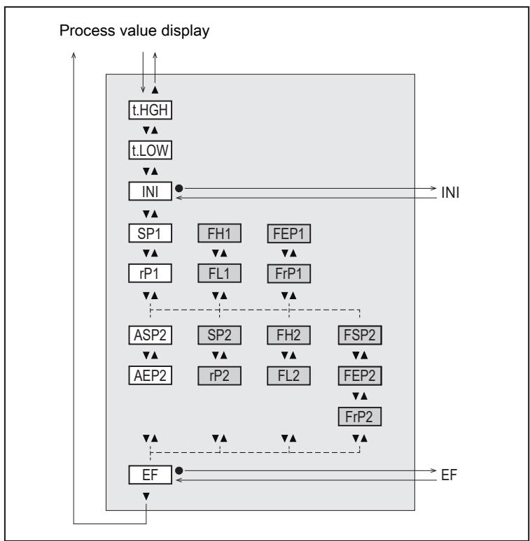
Fig. 18: Main menu
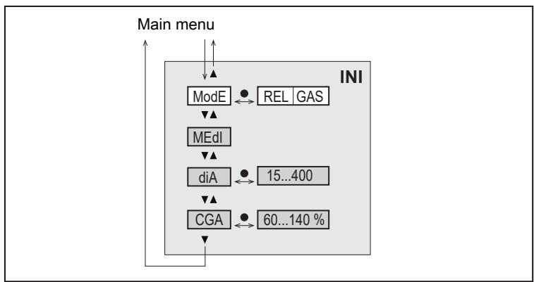
Fig. 19: Initialisation menu INI

Fig. 20: Menu Extended functions EF

Fig. 21: Menu Basic settings CFG
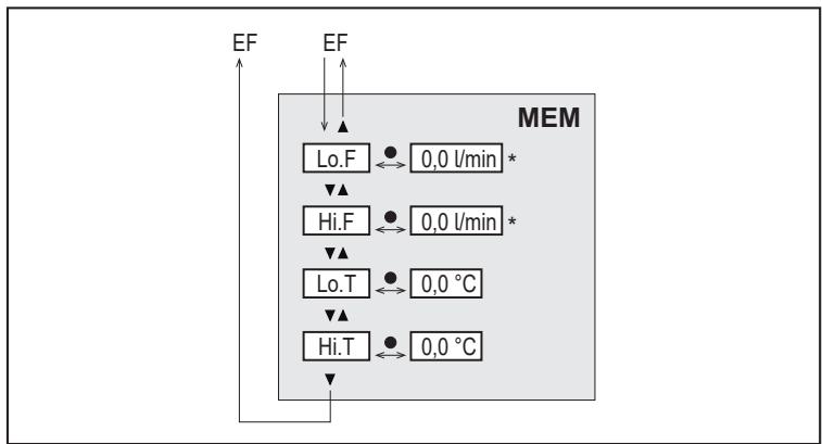
Fig. 22: Menu Min/max memory MEM
* Measured value in the standard unit of measurement ( → Standard unit of measurement for flow ☐ 24)
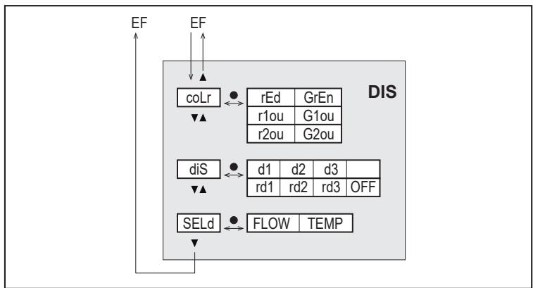
Fig. 23: Menu Display settings DIS
10 Set-up
After power on and expiry of the power-on delay time, the unit is in the normal operating mode. It carries out its measurement and evaluation functions and generates output signals according to the set parameters.
During the power-on delay time the outputs are switched as programmed:
• ON with normally open function (Hno / Fno)
• OFF with normally closed function (Hnc / Fnc)
• OFF for frequency output (FRQ)
• 20 mA for current output (I)
11 Parameter setting

CAUTION
If the medium temperature is above 50\ °C ( 122\ °F ), parts of the housing can increase in temperature to over 65\ °C ( 149\ °F ).
▷ Risk of burns
▶ Do not touch the device with your hands.
▶ Use another object (e.g. a ballpoint pen) to carry out settings on the unit.
Parameters can be set before installation and set-up of the unit or during operation.

If you change parameters during operation, this will influence the function of the plant.
▶ Ensure that there will be no malfunctions in your plant.
During parameter setting the unit remains in the operating mode. It continues to monitor with the existing parameter until the parameter setting has been completed.

The parameters can also be set via the IO-Link interface.
11.1 Parameter setting in general
| Intention | Action |
| Change from the process value display to the main menu | [●] |
| Change to the submenu | Use [▼] to navigate to the sub-menu (e.g. EF), then [●] |
| Select the requested parameter | [▲] or [▼] |
| Change to the setting mode | [●] |
| Modification of the parameter value | [▲] or [▼] > 1 s |
| Apply the set parameter | [●] |
| Exit parameter setting without saving | [▲] and [▼] |
| Return to the next higher menu level(repeat several times to reach process value display) | [▲] and [▼] |
| Return to the process value display | >30 seconds (timeout) |
11.2 Presetting

Before setting the parameters, first check the following default settings and change them if necessary:
- [SEL2]: Process value for OUT2
- [ModE]: Operating mode
- [uni]: Standard unit of measurement for flow
11.2.1 Process value for OUT2
▶ Select the CFG menu.
▶ Select [SEL2]. Select process value for output 2:
• TEMP: temperature
- FLOW: flow
11.2.2 Operating mode
▶ Select the INI menu.
▶ Select [ModE] and define the operating mode: REL or GAS.
For the operating mode GAS, an internal pipe diameter must be entered.
When the factory setting is changed ([ModE] = REL), the unit displays [≡≡≡] to force the entry of the internal pipe diameter:
▶ Press [●] to display [diA].
▶ Define the internal pipe diameter in mm.
The operating mode REL requires a flow adjustment ( → Flow adjustment ☐ 24).
A change of the operating mode leads to a restart of the unit. The settings are saved in the respective operating mode, i.e. after a change in the operating mode, the settings are not lost.
11.2.3 Standard unit of measurement for flow
▶ Select the CFG menu.
▶ Select [uni] and set the unit of measurement: l/min; m3/h ; m/s.
uni is only available if the operating mode GAS is selected. For the operating mode REL the flow value is always displayed in % of the measuring range.
11.2.4 Internal pipe diameter
▶ Select the INI menu.
▶ Select [diA] and define the internal pipe diameter.
diA is only available if the operating mode GAS is selected.
11.2.5 Flow adjustment
High-flow adjustment:
▶ Activate the maximum flow in the installation.
▶ Select the main menu.
▶ Select [t. HGH] and press [●].
▷ [tch] is displayed.
▶ Keep [▲] or [▼] pressed.
▷ [----] is displayed.
▶ Briefly press [●].
▷ Display [donE]: adjustment successful.
▷ Display [FAIL]: repeat the adjustment.
▷ The unit defines the existing flow as maximum flow (final value of the measuring range = 100 %).
▶ Briefly press [●].
Low-flow adjustment:
▶ Activate the minimum flow in the installation.
▶ Select the main menu.
▶ Select [t. LOW] and press [●].
▷ [tch] is displayed.
▶ Keep [▲] or [▼] pressed.
▷ [----] is displayed.
▶ Briefly press [●].
▷ Display [donE]: adjustment successful.
▷ Display [FAIL]: repeat the adjustment.
▷ The unit defines the existing flow as minimum flow (0 %).
▶ Briefly press [●].

t. HGH and t. LOW are only available if the operating mode REL is selected.
11.2.6 Remote calibration
▶ Select the CFG menu.
▶ Select [ou2] and set tch.
High-flow adjustment:
▶ Apply the operating voltage to pin 2 for 5 to 10 s.
Low-flow adjustment:
▶ Apply the operating voltage to pin 2 for 10 to 15 s.
▷ OUT2 high for 2 s: adjustment successful.
▷ OUT2 high for 1 s: adjustment failed. ▶ Repeat the adjustment.
11.3 Setting the output functions

The parameters for flow monitoring and temperature monitoring are set in the same way. The prerequisite is that the process value for OUT2 has first been defined via [SEL2] ( → Process value for OUT2 ☐ 23).
11.3.1 Limit monitoring OUTx / hysteresis function
▶ Select the CFG menu.
▶ Select [oux] and set the switching signal:
• Hno: hysteresis function / normally open
• Hnc: hysteresis function / normally closed
▶ Select the main menu.
▶ Select [SPx] and set the measured value at which the output switches.
▶ Select [rPx] and set the measured value at which the output switches off.
11.3.2 Limit monitoring OUTx / window function
▶ Select the CFG menu.
▶ Select [oux] and set the switching signal:
• Fno: window function / normally open
• Fnc: window function / normally closed
▶ Select the main menu.
▶ Select [FHx] and set the upper limit of the window section.
▶ Select [FLx] and set the lower limit of the window section.
11.3.3 Frequency signal OUTx
▶ Select the CFG menu.
▶ Select [oux] and set FRQ.
▶ Select the main menu.
▶ Select [FSP2] and set the lower temperature value at which 0 Hz is provided.

FSP2 is only available for temperature measurement at OUT2.
▶ Select [FEPx] and set the upper measurement value at which the maximum frequency is provided.

For flow measurement the following applies: FEP1x is only available if the operating mode GAS is selected.
▶ Select [FrPx] and set the maximum frequency: 100 Hz...1000 Hz.
11.3.4 Analogue signal OUT2
▶ Select the CFG menu.
▶ Select [ou2] and set the function:
I: flow-proportional current signal 4...20 mA.
▶ Select the main menu.
▶ Select [ASP2] and set the measurement value at which the output signal is 4 mA.
▶ Select [AEP2] and set the measurement value at which the output signal is 20 mA.

For flow measurement the following applies: ASP2 and AEP2 are only available if the operating mode GAS is selected.
11.4 User settings (optional)
11.4.1 Standard display
▶ Select the DIS menu.
▶ Select [SELd] and set the standard unit of measurement:
- FLOW: The current flow in the standard unit of measurement is displayed.
• TEMP: The current medium temperature in °C is displayed.
▶ Select [diS] and set the update rate and orientation of the display:
• d1, d2, d3: update of the measured values every 50, 200, 600 ms.
- rd1, rd2, rd3: display as with d1, d2, d3; rotated by 180° .
• OFF: The process value display is deactivated in the RUN mode.

The LEDs remain active even if the display is deactivated. Error messages are displayed even if the display is deactivated.
11.4.2 Display colour setting
▶ Select the DIS menu.
▶ Select [coLr] and define the colour of the characters in the process value display:
- rEd: red
- GrEn: green
- rxou: colour change from green to red
• Gxou: colour change from red to green
11.4.3 Output logic
▶ Select the CFG menu.
▶ Select [P-n] and set PnP or nPn.
11.4.4 Measured value damping
▶ Select the CFG menu.
▶ Select [dAP] and set the damping constant in seconds ( τ value 63 %).
11.4.5 Switch-on /switch-off delay
▶ Select the CFG menu.
▶ Select [dSx] and set the delay for switching OUTx in seconds.
▶ Select [drx] and set the delay for resetting OUTx in seconds.
11.4.6 Error behaviour of the outputs
▶ Select the CFG menu.
▶ Select [FOUx] and set the error behaviour for OUTx:
- Switching output
- On: Output switches ON in case of a fault.
– OFF: Output switches OFF in case of a fault.
- OU: Output switches irrespective of the error as defined with the parameters.
- Analogue output
-
On: The analogue signal goes to 22 mA.
– OFF: The analogue signal goes to 3.5 mA.
– OU: The analogue signal still corresponds to the measured value. -
Frequency output
- On: The frequency signal goes to 130% of FrPx.
– OFF: The frequency signal goes to 0 Hz.
– OU: The frequency signal still corresponds to the measured value.
11.4.7 Calibration
▶ Select the INI menu.
▶ Select [CGA] and set a value between 60 and 140 % (100 % = factory setting).

CGA is only available if the operating mode GAS is selected.
11.4.8 Lock / unlock
The unit can be locked electronically to prevent unintentional settings. Factory setting: not locked.
Locking:
▶ Make sure that the unit is in the normal operating mode.
▶ Press [▲] and [▼] simultaneously for 10 s until [Loc] displayed.
Unlocking:
▶ Make sure that the unit is in the normal operating mode.
▶ Press [▲] and [▼] simultaneously for 10 s until [uLoc] is displayed.
11.4.9 Factory reset
▶ Select the EF menu.
▶ Select [rES].
▶ Briefly press [●].
▶ Keep [▼] or [▲] pressed.
▷ [----] is displayed.
▶ Briefly press [●].
▷ The unit carries out a reboot.

We recommend documenting your own settings in the chapter Factory setting before carrying out a reset.
11.5 Diagnostic functions
11.5.1 Reading minimum values / maximum values
▶ Select the MEM menu.
▶ Select [Lo.x] or [Hi.x] to display the highest or lowest process value measured:
- Lo. F: minimum value of the flow value measured in the process (flow volume or flow velocity)
• Hi. F: maximum value of the flow value measured in the process (flow volume or flow velocity)
- Lo. T: minimum value of the temperature measured in the process
• Hi. T: maximum value of the temperature measured in the process
Delete memory:
▶ Select [Lo.x] or [Hi.x].
▶ Keep [▲] and [▼] pressed.
▷ [----] is displayed.
▶ Briefly press [●].

It makes sense to delete the memories as soon as the unit operates under normal operating conditions for the first time.

In the operating mode REL a new teaching process deletes the memory.
12 Operation
After power on and expiry of the power-on delay time, the unit is in the normal operating mode. It carries out its measurement and evaluation functions and generates output signals according to the set parameters.
12.1 Process value display
The device keys can be used to switch between different process value displays during operation:
▶ Press [▲] or [▼] until the required display appears.
▷ The display switches between the views. The indicator LEDs signal the unit of the displayed value.
▷ After 30 s, the device returns to the standard display.
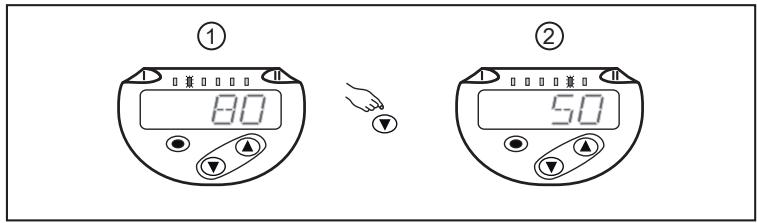
Fig. 24: Process value display
1: Standard display as set under [SELd] and [uni].
Example: [SELd] = FLOW and [uni] = m/s
2: The LED indicates in which unit the current process value is displayed.
Example: temperature in ° C.
12.2 Reading the parameter setting
▶ Briefly press [●].
▶ Press [▼] to select the parameter.
▶ Briefly press [●].
▷ The currently set value is displayed for 30 s. Then the unit returns to the process value display.
13 Technical data
Technical data and scale drawing at www.ifm.com.
14 Troubleshooting
The unit has many self-diagnostic options. It monitors itself automatically during operation.
Warnings and error states are displayed even if the display is switched off. Error indications are also available via IO-Link.
The status signals are classified according to NAMUR recommendation NE107.
If several diagnostic events occur simultaneously, only the diagnostic message of the event with the highest priority is displayed.

Additional diagnostic functions are available via IO-Link → IODD interface description at www.ifm.com.
14.1 Error messages
| Display | Problem/remedy |
| Err | Unit faulty / malfunction▶ Replace the unit. |
| None Display | • Supply voltage too low▶ Check the supply voltage.• Display switched off▶ Check whether setting diS = OFF and change setting if necessary. |
| PARA | Parameter setting outside the valid range▶ Check parameter setting. |
14.2 Warning messages
| Display | Problem/remedy |
| Loc | Setting buttons on the unit locked, parameter change rejected.► Unlock unit (→Lock / unlock □ 28). |
| C. Loc | Setting buttons on the unit temporarily locked, parameter setting via IO-Link communication active.► ▶ Finish parameter setting via IO-Link communication. |
| S. Loc | Setting buttons locked via parameter setting software, parameter change rejected.► ▶ Unlock the unit via IO-Link interface using the parameter setting software. |
| UL | Value below the minimum value of the temperature display range: temperature value < -44 °C.► ▶ Check the temperature range. Value below the minimum value of the flow measuring range▶ Adjust flow. ▶ Repeat low-flow adjustment. |
| OL | Temperature display range exceeded: temperature value < 124 °C.► ▶ Check the temperature range. Flow display range exceeded: flow > 120 % of the final value of the measuring range. ▶ Adjust flow. ▶ Repeat high-flow adjustment. |
| SC1 | Switching status LED for OUT1 flashing: short circuit OUT1.► ▶ Check switching output OU1 for short circuit or excessive current. |
| SC2 | Switching status LED for OUT2 flashing: short circuit OUT2.► ▶ Check switching output OUT2 for short circuit or excessive current. |
| SC | Switching status LEDs for OUT1 and OUT2 flashing: short circuit OUT1 and OUT2.► ▶ Check switching outputs OUT1 and OUT2 for short-circuit or excessive current. |
| FAIL | Faulty low-flow or high-flow adjustment (e.g. the distance between maximum and minimum flow is too small).► ▶ Repeat flow adjustment. |
15 Maintenance, repair and disposal
Only the manufacturer is allowed to repair the unit.
▶ Ensure that the sensor tip is free from build-up:
- Check the sensor tip for build-up one month after set-up.
- Repeat check regularly. Determine check intervals based on the application.
- In case of soiling clean the sensor tip with a soft cloth. Stubborn build-up, such as lime, can be removed using a common vinegar cleaning agent.
▶ After use dispose of the device in an environmentally friendly way in accordance with the applicable national regulations.
16 Factory settings
The factory-set operating mode is REL.
| Parameter | Factory setting | User setting | |
| ModE = REL | ModE = GAS | ||
| SP1 (FLOW) | 20 % | 6 m/s | |
| rP1 (FLOW) | 15 % | 4.6 m/s | |
| FH1 (FLOW) | 20 % | 6 m/s | |
| FL1 (FLOW) | 15 % | 4.6 m/s | |
| FEP1 (FLOW) | 100 % | 30 m/s | |
| FrP1 | 100 Hz | ||
| SP2 (FLOW) | 40 % | 12 m/s | |
| rP2 (FLOW) | 35 % | 10.6 m/s | |
| SP2 (TEMP) | 28 °C | ||
| rP2 (TEMP) | 26 °C | ||
| FH2 (FLOW) | 40 % | 12 m/s | |
| FL2 (FLOW) | 35 % | 10.6 m/s | |
| FH2 (TEMP) | 28 °C | ||
| FL2 (TEMP) | 26 °C | ||
| FSP2 (FLOW) | Not available | ||
| FSP2 (TEMP) | -20 °C | ||
| FEP2 (FLOW) | 100 % | 30 m/s | |
| FEP2 (TEMP) | 100 °C | ||
| FrP2 | 100 Hz | ||
| ASP2 (FLOW) | Not available | 0 m/s | |
| AEP2 (FLOW) | Not available | 30 m/s | |
| ASP2 (TEMP) | -20 °C | ||
| AEP2 (TEMP) | 100 °C | ||
| uni | Not available | m3/h | |
| CGA | Not available | 100 % | |
| ou1 | Hno | ||
| ou2 | I | ||
| dS1 | 0 s | ||
| dr1 | 0 s | ||
| dS2 | 0 s | ||
| dr2 | 0 s | ||
| P-n | PnP | ||
| dAP | 0.6 s | ||
| FOU1 | OFF | ||
| FOU2 | OFF | ||
| SEL2 | FLOW | ||
| coLr | rEd | ||
| diS | d2 | ||
| SELd | FLOW | ||
The percentage values refer to the final value of the measuring range (MEW).
- 1 PRELIMINARY NOTE
- 1.1 SYMBOLS USED
- 1.2 WARNINGS
- 2 SAFETY INSTRUCTIONS
- 3 GETTING STARTED
- 3.1 DEVICE FUNCTION WITH FACTORY SETTING
- 4 FUNCTIONS AND FEATURES
- 4.1 APPLICATION AREA
- 5 FUNCTION
- 5.1 OUTPUT OUT1 SELECTION OPTIONS
- 5.2 OUTPUT OUT2 SELECTION OPTIONS
- 5.3 OPERATING MODES
- 5.4 CALIBRATION
- 5.5 SWITCHING OUTPUT
- 5.6 ANALOGUE OUTPUT
- 5.7 FREQUENCY OUTPUT
- 5.8 MEASURED VALUE DAMPING
- 5.9 DISPLAY COLOUR SETTING
- 5.10 IO-LINK
- 5.10.1 IO-LINK PROCESS VALUES
- 6 INSTALLATION
- 6.1 PROCESS CONNECTION
- 6.2 INTERFERENCE
- 6.3 INSTALLATION POSITION
- 6.3.1 IMMERSION DEPTH
- 6.3.2 RECOMMENDED MOUNTING POSITION
- 6.3.3 CONDITIONALLY POSSIBLE INSTALLATION POSITION
- 6.3.4 IMPERMISSIBLE INSTALLATION POSITION
- 6.3.5 ALIGNMENT
- 7 ELECTRICAL CONNECTION
- 8 OPERATING AND DISPLAY ELEMENTS
- 9 MENU
- 9.1 MENU OVERVIEW
- 9.2 MAIN MENU AND SUBMENUS
- 10 SET-UP
- 11 PARAMETER SETTING
- 11.1 PARAMETER SETTING IN GENERAL
- 11.2 PRESETTING
- 11.2.1 PROCESS VALUE FOR OUT2
- 11.2.2 OPERATING MODE
- 11.2.3 STANDARD UNIT OF MEASUREMENT FOR FLOW
- 11.2.4 INTERNAL PIPE DIAMETER
- 11.2.5 FLOW ADJUSTMENT
- 11.2.6 REMOTE CALIBRATION
- 11.3 SETTING THE OUTPUT FUNCTIONS
- 11.3.1 LIMIT MONITORING OUTX / HYSTERESIS FUNCTION
- 11.3.2 LIMIT MONITORING OUTX / WINDOW FUNCTION
- 11.3.3 FREQUENCY SIGNAL OUTX
- 11.3.4 ANALOGUE SIGNAL OUT2
- 11.4 USER SETTINGS (OPTIONAL)
- 11.4.1 STANDARD DISPLAY
- 11.4.2 DISPLAY COLOUR SETTING
- 11.4.3 OUTPUT LOGIC
- 11.4.4 MEASURED VALUE DAMPING
- 11.4.5 SWITCH-ON /SWITCH-OFF DELAY
- 11.4.6 ERROR BEHAVIOUR OF THE OUTPUTS
- 11.4.7 CALIBRATION
- 11.4.8 LOCK / UNLOCK
- 11.4.9 FACTORY RESET
- 11.5 DIAGNOSTIC FUNCTIONS
- 11.5.1 READING MINIMUM VALUES / MAXIMUM VALUES
- 12 OPERATION
- 12.1 PROCESS VALUE DISPLAY
- 12.2 READING THE PARAMETER SETTING
- 13 TECHNICAL DATA
- 14 TROUBLESHOOTING
- 14.1 ERROR MESSAGES
- 14.2 WARNING MESSAGES
- 15 MAINTENANCE, REPAIR AND DISPOSAL
- 16 FACTORY SETTINGS
Brand : IFM
Model : SA4120
Category : Detector