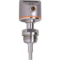
SI6700 - Detector IFM - Free user manual and instructions
Find the device manual for free SI6700 IFM in PDF.


User questions about SI6700 IFM
0 question about this device. Answer the ones you know or ask your own.
Ask a new question about this device
Download the instructions for your Detector in PDF format for free! Find your manual SI6700 - IFM and take your electronic device back in hand. On this page are published all the documents necessary for the use of your device. SI6700 by IFM.
USER MANUAL SI6700 IFM
Operating instructions
Flow monitor
SI6600
SI6700
SI6800
Contents
1 Preliminary note.... 3
1.1 Symbols used.... 3
1.2 Warnings.... 3
2 Safety instructions 4
3 Transport, handling and storage 5
4 Intended use 6
5 Function 7
6 Installation.... 8
6.1 Installation position 8
6.1.1 Immersion depth 8
6.1.2 Recommended mounting position 8
6.1.3 Conditionally possible installation position.... 9
6.1.4 Impermissible installation position.... 9
6.1.5 Orientation.... 10
6.2 Interference.... 10
6.3 Process connection.... 10
6.3.1 Installation using an adapter with sealing ring (hygiene-compliant).... 11
6.3.2 Installation using a welding adapter with sealing ring (hygiene-compliant).... 11
6.3.3 Installation using a process adapter with metal-to-metal seal 11
6.3.4 Installation to G1 flange 11
6.3.5 Use in hygienic areas according to 3-A 12
6.3.6 Use in hygienic areas to EHEDG 12
7 Electrical connection 14
8 Operating and display elements.... 15
9 Set-up 16
10 Settings.... 17
10.1 Changing the switch point 17
10.2 High-flow adjustment.... 17
10.3 Low-flow adjustment 17
10.4 Switch point logic 18
10.5 Reset the device.... 18
10.6 Lock/unlock 18
11 Operation.... 19
12 Troubleshooting.... 20
13 Maintenance, repair and disposal 21
1 Preliminary note
You will find instructions, technical data, approvals, accessories and further information using the QR code on the device / packaging or at documentation.ifm.com.
1.1 Symbols used
√ Requirement
Instruction
Reaction, result
bold Designation of keys, buttons or indications
→ Cross-reference without link
→ Cross-reference with link

Important note
Non-compliance may result in malfunction or interference

Information
Supplementary note
1.2 Warnings
Warnings indicate the possibility of personal injury and damage to property. This enables safe product handling. Warnings are graded as follows:

WARNING
Warning of serious personal injury
▷ If the warning is not observed, fatal and serious injuries are possible.

CAUTION
Warning of minor to moderate personal injury
▷ If the warning is not observed, minor to moderate injuries are possible.

ATTENTION
Warning of damage to property
▷ If the warning is not observed, damage to property is possible.
2 Safety instructions
- The unit described is a subcomponent for integration into a system.
- The system architect is responsible for the safety of the system.
-
The system architect undertakes to perform a risk assessment and to create documentation in accordance with legal and normative requirements to be provided to the operator and user of the system. This documentation must contain all necessary information and safety instructions for the operator, the user and, if applicable, for any service personnel authorised by the architect of the system.
-
Read this document before setting up the product and keep it during the entire service life.
- The product must be suitable for the corresponding applications and environmental conditions without any restrictions.
- Only use the product for its intended purpose (→ Intended use).
- Only use the product for permissible media.
- If the operating instructions or the technical data are not adhered to, personal injury and/or damage to property may occur.
- The manufacturer assumes no liability or warranty for any consequences caused by tampering with the product or incorrect use by the operator.
- Installation, electrical connection, set-up, operation and maintenance of the product must be carried out by qualified personnel authorised by the machine operator.
- Protect units and cables against damage.
3 Transport, handling and storage
▶ Store the device in its original packaging.
▶ When the device is to be stored again, use the original packaging.
▶ Otherwise, provide unused connections with either a mating connector or a protective cap and pack the device in suitable packaging.
▶ Observe the permissible ambient conditions for the device during storage (→ Technical data).
4 Intended use
The device monitors the flow in liquid and gaseous media.
For use in general or hygienic applications in the food and beverage industry.
5 Function
The device detects flow based on the calorimetric measuring principle and switches the output.
With the factory default setting, the switch point is at LED 7.
The device's output is set to a normally open contact by default and can be switched to a normally closed contact.
The switch point LED indicates the switching status:
• LED orange = output closed.
• LED red = output open.
Normal operation
With normal flow, the output has the following status:
• Output closed for normally open function.
• Output open for normally closed function.

Fig. 1: Flow ≥ SP / normally open function

Fig. 2: Flow ≥ SP / normally closed function
Deviation from normal operation
If the flow velocity decreases, the switching status changes when the value falls below the switch point SP minus the hysteresis.

Fig. 3: Flow < SP / normally open function

Fig. 4: Flow < SP / normally closed function

The hysteresis changes with the flow velocity and it is essentially influenced by the set monitoring range. It is 2...5 cm/s for the setting 5...100 cm/s (= factory setting), it increases with higher flow velocities.
The typical response time of the device is 1 ... 10 s. It can be influenced by the setting of the switch point:
- Low switch point = quick reaction with rising flow.
- High switch point = quick reaction with falling flow.
6 Installation

CAUTION
During installation or in case of mechanical failure, high pressure or hot media can leak from the system.
▷ Risk of injury caused by pressure or burns.
▶ Ensure that the system is free of pressure during installation.
▶ Ensure that no media can leak at the mounting location during installation.
6.1 Installation position
6.1.1 Immersion depth


Fig. 5: Immersion depth
- The sensor tip must be completely surrounded by the medium.
- Recommended immersion depths: minimum 12 mm.
6.1.2 Recommended mounting position


Fig. 6: Recommended mounting position
- For horizontal pipes: mounting from the side.
- For vertical pipes: mounting in the rising pipe.
6.1.3 Conditionally possible installation position

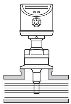
Fig. 7: Conditionally possible installation position
- For horizontal pipes, if the pipe is free from build-up: mounting from below.
- For horizontal pipes, if the pipe is completely filled with medium: mounting from the top.
6.1.4 Impermissible installation position
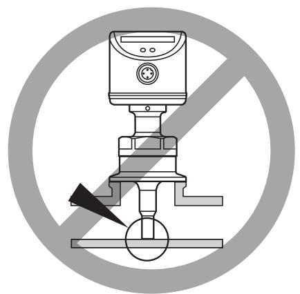
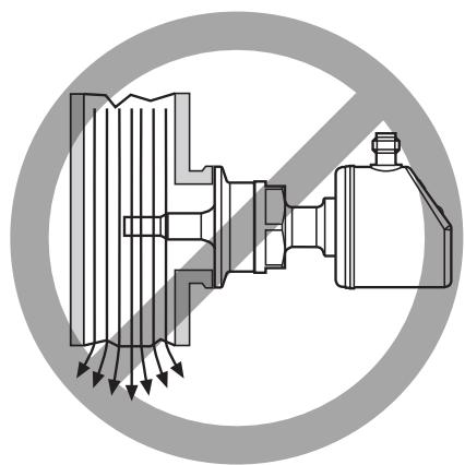
Fig. 8: Impermissible installation position
- The sensor tip must not be in contact with the pipe wall.
- Do not mount in downpipes that are open at the bottom.
6.1.5 Orientation
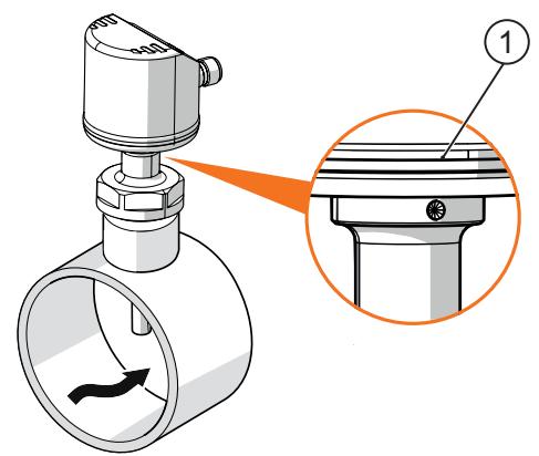
Fig. 9: Flow direction (arrow)
▶ To ensure optimum measurement accuracy, install the sensor so that the connector is facing away from the direction of flow.

The side opposite the direction of flow is also marked by a hole above the wrench flat (1).
6.2 Interference
Structures in the pipe, bends, valves, reducing pieces and the like affect the function of the unit.
▶ Adhere to the distances between sensor and interference.
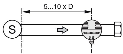

Fig. 10: Inlet and outlet pipe lengths
D: Outside diameter of the pipe
S: Interference
6.3 Process connection
Using process adapters the unit can be adapted to different process connections. Adapters have to be ordered separately as accessories.
• Information about the available mounting accessories at www.ifm.com.
- A correct fit of the unit and ingress resistance of the connection are only ensured using ifm adapters.

▶ Observe the instructions of the mounting accessories.

▶ Use a lubricating paste which is suitable and approved for the application. Grease the threads of the process connection, adapter and sensor. Ensure no grease is applied to the sensor tip.
▶ Insert the unit with the process adapter into the process connection, then tighten it using a spanner. Recommended tightening torque: 35 Nm.
6.3.1 Installation using an adapter with sealing ring (hygiene-compliant)
Order no. E332xx / E333xx
▶ To meet the hygiene regulations use a process adapter with leakage port.
The adapters are supplied with EPDM O-ring (order no. E30054).
More sealing rings are available as accessories:
• FKM O-ring (order no. E30123);
- PEEK sealing ring (order no. E30124).
The PEEK sealing ring is long-term stable and maintenance-free. When you replace the PEEK sealing ring or change from a PEEK sealing ring to an O-ring, the process adapter also needs to be replaced with a new equivalent adapter.
6.3.2 Installation using a welding adapter with sealing ring (hygiene-compliant)
▶ To meet the hygiene regulations use a process adapter with leakage port.
▶ Make sure that the process adapter does not warp during welding.
The adapter is supplied with EPDM O-ring (order no. E30054).
Another sealing ring is available as accessory:
• FKM O-ring (order no. E30123).
6.3.3 Installation using a process adapter with metal-to-metal seal
Order no. E337xx / E338xx

ATTENTION
Loss of sealing effect on reassembly
▷ A long-term stable, maintenance-free and gap-free fitting in the metal-to-metal seal is only valid for once-only mounting.
▶ Use a new adapter if the sealing is installed several times.
6.3.4 Installation to G1 flange
The process is sealed with the sealing ring at the back of the sensor.
The sealing area at the flange must be flush with the tapped hole and have a surface characteristic of min. Rz = 6.3.
6.3.5 Use in hygienic areas according to 3-A
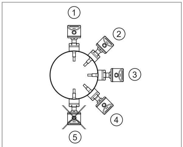
Fig. 11: Use according to 3-A
The following applies to units with 3-A certification:
▶ Only use adapters with 3-A certification for the process connection.
▶ Do not install the unit at the lowest point of the pipe or tank (position 5) in order that the medium can run off the area of the measuring element.
▶ Ensure that the installation of the device in the system complies with 3-A guidelines.
▶ Use self-draining installation.

Not suitable for systems that have to meet the criteria of E9.2 / 63-04 of the 3-A standard 63-04.
6.3.6 Use in hygienic areas to EHEDG

The sensor is suited for CIP (clean in place) when installed correctly.
▶ Observe the application limits (temperature and material resistance) according to the data sheet.
▶ Ensure that the installation of the unit in the system complies with EHEDG.
▶ Use self-draining installation.
▶ Only use process adapters permitted according to EHEDG with special seals required by the EHEDG position paper.

The gasket of the system interface must not be in contact with the sealing point of the sensor.

When mounted in a tank, the installation must be flush mount or direct water jet cleaning must be possible. Dead spaces must be included.
▶ Leakage ports must be clearly visible and must be installed facing downwards for vertical pipes.
▶ Adhere to the dimensions shown in the following figure to avoid dead spaces that cannot be cleaned effectively: L < (D - d).

Fig. 12: Use according to EHEDG
1: Leakage port
7 Electrical connection

The unit must be connected by a qualified electrician.
Observe the national and international regulations for the installation of electrical equipment. Voltage supply according to SELV, PELV.
▶ Disconnect power.
▶ Connect the unit as follows:


Fig. 13: Wiring
1: Ub+
3: Ub-
4: Digital output (PNP): Switching signal flow
8 Operating and display elements

1: Operation indication
- The LEDs 0...9 represent the range between flow standstill and maximum flow.
- The green LEDs show the current flow.
- An illuminated LED shows the position of the switch point:
- Orange: output closed
- Red: output open
In the current example: normally open function (factory setting).
2: Setting buttons for adjustment and configuration
9 Set-up
▶ Switch on the supply voltage.
▷ All LEDs light and go out again step by step. During this time, the output is closed if set to normally open and open if set to normally closed.
▷ The device is in the operating mode.
▶ Let the normal flow circulate in the installation.
▶ Check the display and determine further actions:
| Display | Explanation | |
| 1 | 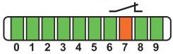 | The factory set operating range is suited for the application.► ▶ If necessary, adjust the switch point to suit the application. |
| 2 |  | The normal flow is below the display range.► ▶ Carry out high-flow adjustment.► ▶ Ajust the switch point to the application. |
| 3 |  | Your normal flow exceeds the representation range of the display (LED 9 flashes).► ▶ Carry out high-flow adjustment. |
Tab. 1: Display settings at factory settings (→ Function)

The factory settings can be restored at any time (→ Reset Device).

For media other than water:
▶ Perform an additional calibration for minimum flow (→ Low-flow adjustment).
10 Settings
10.1 Changing the switch point
For the factory setting the switch point is at LED 7. A change makes sense in the following cases:
-
The normal flow falls below the representation range of the display, see ➞ 16.
• The flow fluctuates strongly or pulsates.
• A faster response time of the device is required. -
Low switch point = quick reaction with rising flow.
– High switch point = quick reaction with falling flow.
▶ Briefly press the Ⓓ or ⬇ button.
▷ The switch point LED flashes.
▶ Press Ⓓ or ▶ as often as required.
▷ Each press of the pushbutton shifts the LED by one position in the indicated direction.
▶ When the required switch point is reached, do not press the button for more than 2 seconds.
▷ The device goes into operating mode with the newly set value.
10.2 High-flow adjustment
The device defines the current flow as the normal flow and adapts the display accordingly.
▶ Let the normal flow circulate in the installation.
▶ Press the ⬤ button and keep it pressed..
▷ LED 9 is on, after approx. 5 seconds it flashes.
▶ Release the ⬤ button.
▷ The device is adapted to the flow conditions. It goes into operating mode.
▷ The display should now show an LED indication similar to example 1 → 16.

If all LEDs are flashing red, the adjustment has failed. Possible causes ➕ Chapter “Troubleshooting”. The device switches to operating mode with unchanged values.

The adjustment affects the switch point: It is increased proportionally (maximum up to LED 7).
10.3 Low-flow adjustment
If the device is used in media other than water, the device should additionally be adapted to the minimum flow.

The low-flow adjustment may only be carried out after the high-flow adjustment.
▶ Let the minimum flow circulate in the installation or ensure flow standstill.
▶ Press the Ⓐ button and keep it pressed.
▷ LED 0 is on, after approx. 5 seconds it flashes.
▶ Release the Ⓓ button.
▷ The device adopts the new value and enters operating mode.
10.4 Switch point logic
Upon delivery, the device is set to normally open.
Changeover to normally closed function:
▶ Press the Ⓐ button for at least 15 seconds.
▷ LED 0 is on, after approx. 5 seconds it flashes.
▷ After 10 seconds the current setting is displayed: LEDs 5...9 light orange (= output normally open).
▷ After approx. 15 seconds LEDs 0...4 flash orange.
▶ Release the Ⓓ button.
▷ The output is changed to normally closed function.
▶ For a new changeover repeat the operation.
10.5 Reset the device
▶ Press the ⬤ button for at least 15 seconds.
▷ LED 9 is on, after approx. 5 seconds it flashes.
▷ After approx. 15 seconds LEDs 0...9 flash orange.
▶ Release the ⬤ button.
▷ All settings are reset to the factory setting:
• Operating range: 5 ...100 cm/s for water
- Switch point: LED 7
• Output function: normally open
- Not locked
10.6 Lock / unlock
The unit can be locked electronically to prevent unauthorised setting.
Factory setting: not locked.
▶ Press both setting keys for 10 seconds.
▷ The display goes off.
▷ The unit is locked.
▶ For unlocking repeat the process.
11 Operation
The device detects the flow and switches the outputs according to the parameter setting.
The device displays the current flow and the switching status.

In case of power failure or interruption of the operating voltage, all settings remain.
| Display | Explanation | |
| 1 | 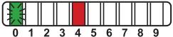 LED 0 flashes LED 0 flashes | Current flow below the display range. |
| 2 |  | Current flow below the switch point. |
| 3 |  | Current flow corresponds to the switch point. |
| 4 | 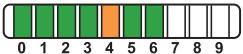 | Current flow above the switch point. |
| 5 |  LED 9 flashes LED 9 flashes | Current flow above the display range. |
Tab. 2: Display for normally open function, switch point at LED 4
LED orange: output closed; LED red: output open
12 Troubleshooting
| Display | Description | Corrective measures |
| The LED display turns off briefly (0.6 s) when a button is pressed. | The device is permanently locked. | ▸ Unlock device. |
 LEDs are permanently off. LEDs are permanently off. | Operating voltage too low (< 19 V) or failed. | ▸ Ensure correct voltage supply. |
 Operating indicator and red LEDs light alternately. Operating indicator and red LEDs light alternately. | Short circuit at the switching output. | ▸ Remove short circuit.▸ ▷ The device immediately returns to the normal operating status and the current operating indication appears in the display. |
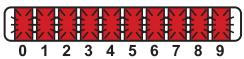 LEDs flash red after flow adjustment. The device then returns to the operating mode with unchanged values. LEDs flash red after flow adjustment. The device then returns to the operating mode with unchanged values. | High-flow adjustment or low-flow adjustment not successful. | ▸ Check whether all installation requirements have been met.▸ Increase the distance between maximum flow and minimum flow and carry out the adjustment again.▸ ▶ Carry out the two adjustment operations again in the right sequence. |
13 Maintenance, repair and disposal
Only the manufacturer is allowed to repair the unit.
▶ Ensure that the sensor tip is free from build-up:
- Check the sensor tip regularly for deposits. Determine check intervals based on the application.
- In case of soiling clean the sensor tip with a soft cloth. Stubborn build-up, such as lime, can be removed using a common vinegar cleaning agent.
▶ After use, dispose of the unit in an environmentally friendly way in accordance with the applicable national regulations.
- 1 PRELIMINARY NOTE
- 1.1 SYMBOLS USED
- 1.2 WARNINGS
- 2 SAFETY INSTRUCTIONS
- 3 TRANSPORT, HANDLING AND STORAGE
- 4 INTENDED USE
- 5 FUNCTION
- 6 INSTALLATION
- 6.1 INSTALLATION POSITION
- 6.1.1 IMMERSION DEPTH
- 6.1.2 RECOMMENDED MOUNTING POSITION
- 6.1.3 CONDITIONALLY POSSIBLE INSTALLATION POSITION
- 6.1.4 IMPERMISSIBLE INSTALLATION POSITION
- 6.1.5 ORIENTATION
- 6.2 INTERFERENCE
- 6.3 PROCESS CONNECTION
- 6.3.1 INSTALLATION USING AN ADAPTER WITH SEALING RING (HYGIENE-COMPLIANT)
- 6.3.2 INSTALLATION USING A WELDING ADAPTER WITH SEALING RING (HYGIENE-COMPLIANT)
- 6.3.3 INSTALLATION USING A PROCESS ADAPTER WITH METAL-TO-METAL SEAL
- 6.3.4 INSTALLATION TO G1 FLANGE
- 6.3.5 USE IN HYGIENIC AREAS ACCORDING TO 3-A
- 6.3.6 USE IN HYGIENIC AREAS TO EHEDG
- 7 ELECTRICAL CONNECTION
- 8 OPERATING AND DISPLAY ELEMENTS
- 9 SET-UP
- 10 SETTINGS
- 10.1 CHANGING THE SWITCH POINT
- 10.2 HIGH-FLOW ADJUSTMENT
- 10.3 LOW-FLOW ADJUSTMENT
- 10.4 SWITCH POINT LOGIC
- 10.5 RESET THE DEVICE
- 10.6 LOCK / UNLOCK
- 11 OPERATION
- 12 TROUBLESHOOTING
- 13 MAINTENANCE, REPAIR AND DISPOSAL
Brand : IFM
Model : SI6700
Category : Detector