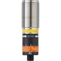
OID200 - Rangefinder IFM - Free user manual and instructions
Find the device manual for free OID200 IFM in PDF.


User questions about OID200 IFM
0 question about this device. Answer the ones you know or ask your own.
Ask a new question about this device
Download the instructions for your Rangefinder in PDF format for free! Find your manual OID200 - IFM and take your electronic device back in hand. On this page are published all the documents necessary for the use of your device. OID200 by IFM.
USER MANUAL OID200 IFM
CE
Operating instructions Optical distance sensor
OID20x

Contents
1 Preliminary note....3
1.1 Symbols used .... 3
1.2 Warning signs used .... 3
2 Safety instructions ....3
3 Functions and features .... 5
3.1 Applications ....5
4 Installation....5
4.1 Installation conditions ....5
5 Electrical connection....5
6 Setting / Operation....6
7 IO-Link 7
7.1 General information....7
7.2 Device-specific information....7
7.3 Parameter setting tools....7
8 Maintenance, repair and disposal....7
1 Preliminary note
1.1 Symbols used
▶ Instruction
▷ Reaction, result
[...] Designation of pushbuttons, buttons or indications
→ Cross-reference

Important note
Non-compliance can result in malfunctions or interference.

Information
Supplementary note.
1.2 Warning signs used

WARNING
Warning of serious personal injury.
Death or serious irreversible injuries may result.
2 Safety instructions
- Please read this document prior to set-up of the unit. Ensure that the product is suitable for your application without any restrictions.
- Improper or non-intended use may lead to malfunctions of the unit or to unwanted effects in your application. That is why installation, electrical connection, set-up, operation and maintenance of the unit must only be carried out by qualified personnel authorised by the machine operator.
- In case of malfunction of the unit please contact the manufacturer. If the unit is tampered with and/or modified, any liability and warranty is excluded.
- The unit conforms to the standard EN 61000-6-4. The unit may cause radio interference in domestic areas. If interference occurs, the user must take appropriate remedial actions.
Visible laser light; laser protection class 2.
Use of controls or adjustments other than those specified herein may result in hazardous radiation exposure. Damage to the retina is possible.
▶ Do not stare into the laser beam!
▶ Apply the enclosed labels (laser warning) in the immediate vicinity of the unit.
▶ Adhere to the caution and warning notes on the product label.
▶ Use the enclosed label for the power supply cable.
▶ EN/IEC 60825-1 : 2007 and EN/IEC 60825-1 : 2014
Complies with 21 CFR 1040.10 except for conformance with IEC 60825-1 Ed. 3., as described in Laser Notice No. 56, dated May 8, 2019.
Label for supply cable
ATTACH TO CABLE

ifm electronic gmbh
WARNING:
CLASS 2 LASER PRODUCT
DO NOT STARE INTO BEAM
- AVOID EXPOSURE
- UNPLUG CONNECTOR TO
EXTINGUISH LASER BEAM
D-45128 Essen
Product label

AVOID EXPOSURE
LASER RADIATION EMITTED
FROM THIS APERTURE

CAUTION LASERRADIATION
DO NOT STARE INTO BEAM
max. POWER ≤ 4,0 mW, PULSE 1,3 ns, λ = 650 nm

CLASS 2 LASER PRODUCT
21 CFR PART 1040
IEC 60825-1:2014

POWER
OID2xx
CLASS 2 LASER PRODUCT
www.ifm.com
CE
TS AA 1301
OUT
3 Functions and features
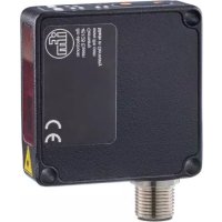
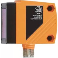
The unit is used as an optical distance sensor.
3.1 Applications
- The optical distance sensor measures distances between 0.03 and 2 m.
- It has a background suppression of up to 20 m.
• The switching outputs are complimentary.

The distance between the sensor and the background must be limited to max. 20 m by the customer. Otherwise the measured value may be ambiguous. → 4.1 Installation conditions
4 Installation
4.1 Installation conditions
▶ Install the unit so that the object to be detected is within a measuring range of 0.03...2 m.
Any object between the set switch point and a distance of 20 m from the sensor is suppressed.

Reflecting objects in the direct beam path of the sensor - also in the range ▷ 20 m – are to be avoided by the customer. Otherwise the measured values may be ambiguous.
5 Electrical connection

The unit must be connected by a qualified electrician.
▶ The national and international regulations for the installation of electrical equipment must be adhered to.
▶ Ensure voltage supply according to EN 50178, SELV, PELV.
▶ Disconnect power.
▶ Connect the unit as follows:
DC PNP

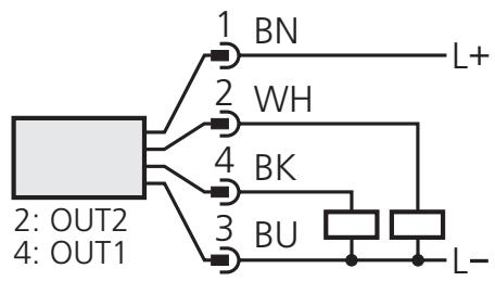
4: OUT1 = normally open / IO-Link
2: OUT2 = normally closed
DC NPN


4: OUT1 = normally open / IO-Link
2: OUT2 = normally closed
Core colours of ifm sockets:
1 = BN (brown), 2 = WH (white), 3 = BU (blue), 4 = BK (black)
6 Setting / Operation

1: Setting marks
2: Yellow LED: Set1 value reached, output = ON
3: Locking ring
4: Setting ring (manually adjustable after unlocking)
5: Green LED: supply voltage O. K.
- To obtain the setting accuracy: Set the ring to the maximum value, then set the requested value.
▶ After mounting, wiring and programming check whether the unit operates correctly.

Lifetime of a laser diode: 50,000 hours
7 IO-Link
7.1 General information
This unit has an IO-Link communication interface which requires an IO-Link-capable module (IO-Link master) for operation.
The IO-Link interface enables direct access to the sensor values and parameters and provides the possibility to set the parameters of the unit during operation.
In addition communication is possible via a point-to-point connection with a USB adapter cable.
You will find more detailed information about IO-Link at www.ifm.com.
7.2 Device-specific information
You will find the IODDs necessary for the configuration of the IO-Link unit and detailed information about sensor values, diagnostic information and parameters in the overview table at www.ifm.com.
7.3 Parameter setting tools
You will find all necessary information about the required IO-Link hardware and software at www.ifm.com.
8 Maintenance, repair and disposal
Faulty sensors must only be repaired by the manufacturer.
▶ Keep the front lens of the sensor free from soiling.
▶ After use dispose of the unit in an environmentally friendly way in accordance with the applicable national regulations.
▶ Do not try to open the module enclosure. There are no user-serviceable components inside.

- 1 PRELIMINARY NOTE
- 1.1 SYMBOLS USED
- 1.2 WARNING SIGNS USED
- 2 SAFETY INSTRUCTIONS
- 3 FUNCTIONS AND FEATURES
- 3.1 APPLICATIONS
- 4 INSTALLATION
- 4.1 INSTALLATION CONDITIONS
- 5 ELECTRICAL CONNECTION
- 6 SETTING / OPERATION
- 7 IO-LINK
- 7.1 GENERAL INFORMATION
- 7.2 DEVICE-SPECIFIC INFORMATION
- 7.3 PARAMETER SETTING TOOLS
- 8 MAINTENANCE, REPAIR AND DISPOSAL
Brand : IFM
Model : OID200
Category : Rangefinder