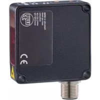
OMH551 - Rangefinder IFM - Free user manual and instructions
Find the device manual for free OMH551 IFM in PDF.


User questions about OMH551 IFM
0 question about this device. Answer the ones you know or ask your own.
Ask a new question about this device
Download the instructions for your Rangefinder in PDF format for free! Find your manual OMH551 - IFM and take your electronic device back in hand. On this page are published all the documents necessary for the use of your device. OMH551 by IFM.
USER MANUAL OMH551 IFM
Operating instructions
Photoelectric distance sensor
OMH550
OMH552
OMH554
Contents
1 Preliminary note 4
1.1 Symbols used 4
1.2 Warnings.... 4
2 Safety instructions.... 5
3 Intended use.... 6
4 Function 7
4.1 Output function hysteresis.... 7
4.2 Output function window 7
4.3 Switching off the laser 7
4.4 Operating modes 7
4.4.1 Switching mode.... 7
4.4.2 IO-Link 7
5 Installation.... 9
5.1 Installation conditions 9
5.2 Mounting accessories 9
5.3 Installation instructions 9
5.3.1 Avoidance of soiling and ambient light 9
5.3.2 Avoidance of mutual interference 9
5.3.3 Sensor alignment for a moving object 9
6 Electrical connection.... 10
6.1 PNP/NPN selection.... 10
7 Operating and display elements 11
7.1 LED states 11
7.2 LED states of the parameters 12
8 Set-up.... 13
9 Parameter setting 14
9.1 Hysteresis function 14
9.1.1 Parameter setting of the switch point via the device buttons 14
9.1.2 Parameter setting of the switch point via IO-Link.... 14
9.1.3 Hysteresis function via IO-Link 14
9.2 Window function 15
9.2.1 Parameter setting via the device buttons.... 15
9.2.2 Parameter setting via IO-Link 15
9.3 Two-point function (Two point mode) 16
9.3.1 Parameter setting via IO-Link 16
9.4 Activating OUT2 16
9.4.1 Parameter setting via IO-Link 16
9.5 Output logic (PNP/NPN) 16
9.5.1 Parameter setting via IO-Link 16
9.6 Output function 17
9.6.1 Parameter setting via the device buttons.... 17
9.6.2 Parameter setting via IO-Link 17
9.7 Lock / unlock the device 17
9.7.1 Parameter setting via the device buttons.... 17
9.7.2 Parameter setting via IO-Link 17
9.8 Indication of current setting (Info mode) 18
9.9 Reset to factory setting 18
9.9.1 Reset via device buttons.... 18
9.9.2 Reset via IO-Link 18
9.10 Additional parameter settings via IO-Link 18
9.10.1 Switch-on delay.... 18
9.10.2 Switch-off delay.... 19
9.10.3 Filter 19
9.10.4 Transmitter configuration.... 19
9.10.5 Switching counter 19
9.10.6 Operating modes 20
10 Setting.... 21
10.1 Setting the range via IO-Link.... 21
10.1.1 Single point mode 21
10.1.1.1 Single point mode to smart sensor profile 21
10.1.1.2 Single point mode to smart sensor profile - Two value teach.... 21
10.1.1.3 Single-point mode - position 21
10.1.1.4 Background suppression.... 22
10.1.2 Window mode 22
10.1.2.1 Window Mode - Two value teach 22
10.1.3 Two point mode 23
11 Troubleshooting 24
12 Maintenance, repair and disposal 25
13 Factory setting 26
1 Preliminary note
You will find instructions, technical data, approvals and further information using the QR code on the unit / packaging or at documentation.ifm.com.
1.1 Symbols used
√ Requirement
Instructions
Reaction, result
[...] Designation of keys, buttons or indications
→ Cross-reference

Important note
Non-compliance may result in malfunction or interference.

Information
Supplementary note
1.2 Warnings
Warnings indicate the possibility of personal injury and damage to property. This enables safe product handling. Warnings are graded as follows:

WARNING
Warning of serious personal injury
▷ If the warning is not observed, fatal and serious injuries are possible.

CAUTION
Warning of minor to moderate personal injury
▷ If the warning is not observed, minor to moderate injuries are possible.
ATTENTION
Warning of damage to property
▷ If the warning is not observed, damage to property is possible.
2 Safety instructions
- The unit described is a subcomponent for integration into a system.
- The system architect is responsible for the safety of the system.
-
The system architect undertakes to perform a risk assessment and to create documentation in accordance with legal and normative requirements to be provided to the operator and user of the system. This documentation must contain all necessary information and safety instructions for the operator, the user and, if applicable, for any service personnel authorised by the architect of the system.
-
Read this document before setting up the product and keep it during the entire service life.
- The product must be suitable for the corresponding applications and environmental conditions without any restrictions.
- Only use the product for its intended purpose ( → → Intended use).
- If the operating instructions or the technical data are not adhered to, personal injury and/or damage to property may occur.
- The manufacturer assumes no liability or warranty for any consequences caused by tampering with the product or incorrect use by the operator.
- Installation, electrical connection, set-up, operation and maintenance of the product must be carried out by qualified personnel authorised by the machine operator.
- Protect units and cables against damage.

CAUTION
Exposure to radiation
▷ Use of controls or adjustments or procedures other than those specified herein may result in hazardous radiation exposure.
▶ Only use the operating and adjusting devices indicated in the operating instructions.

CAUTION
Visible laser light; LASER CLASS 1.
EN/IEC 60825-1 : 2007 and EN/IEC 60825-1 : 2014
Complies with 21 CFR 1040.10 except for conformance with IEC 60825-1 Ed. 3., as described in Laser Notice No. 56, dated May 8, 2019..
Position of the product label

Warning sign

3 Intended use
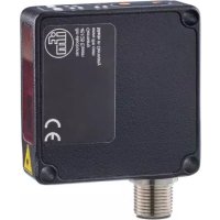
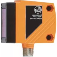
The device is used as a photoelectric distance sensor.
The device continuously detects the distance to the object and generates output signals according to the parameter settings.
- 2 switching outputs are available. They can be set separately. Switch points can either be set or taught.
The device uses a laser diode as light source and creates a light spot. This makes it possible to detect small objects.

The light spot should hit the object or the background. Intermediate states may lead to faulty measured values.
4 Function
4.1 Output function hysteresis
The hysteresis keeps the switching state of the output stable if the measured value varies about the sensing range. Both outputs (OUT1 and OUT2) can be set as hysteresis function.

OUT2 can only be configured via IO-Link.
4.2 Output function window
The window function enables the monitoring of a defined acceptable range. Both outputs (OUT1 and OUT2) can be set as window function.

OUT2 can only be configured via IO-Link.
4.3 Switching off the laser
The laser can be switched off via the input on pin 5 and via IO-Link.
| Input signal on pin 5 | Laser | |
| PNP | NPN | |
| Low / not used | High / not used | On |
| High | Low | Off |
4.4 Operating modes
4.4.1 Switching mode
In switching mode, the sensor is directly connected to the process control unit and transmits the state via the switching output.
4.4.2 IO-Link
IO-Link is a communication system for connecting intelligent sensors and actuators to automation systems. IO-Link is standardised in the IEC 61131-9 standard.

General information on IO-Link at io-link.ifm

Input Output Device Description (IODD) with all parameters, process data and detailed descriptions of the device at documentation.ifm.com
IO-Link offers the following advantages:
• Interference-free transmission of all data and process values
• Parameter setting in the running process or presetting outside the application
- Parameters for identifying the connected devices in the system
• Additional parameters and diagnostic functions
• Automatic backup and restore of parameter sets in case of device replacement (data storage)
- Logging of parameter sets, process values and events
• Device description file (IODD - Input Output Device Description) for easy project planning
• Standardised electrical connection - Remote maintenance
5 Installation
5.1 Installation conditions
▶ Install the device so that the object to be detected is within the sensor's detection zone.
Reflecting objects in the direct beam path of the sensor – also outside the detection zone – are to be avoided by the customer (tilt the sensor by 10° ). Otherwise the measured values can be ambiguous.
Detection zone → Data sheet
5.2 Mounting accessories
The device is supplied without mounting accessories.
Suitable mounting accessories can be found at www.ifm.com.
5.3 Installation instructions
5.3.1 Avoidance of soiling and ambient light
Preferably align photoelectric sensors with the front lens facing downwards or parallel to the earth's surface.
Background:
- Photoelectric sensors are sensitive to direct radiation of light sources. Everyday light sources (lamps, sun) radiate from above.
• Photoelectric sensors react sensitively to soiling, as it reduces the excess gain.
Dust deposits can be reduced by downwards or sideways orientation. This allows for longer cleaning intervals.
Make sure that sensors installed with their front lens facing upwards are not oriented towards roof windows or ceiling lamps.
5.3.2 Avoidance of mutual interference
Photoelectric sensors should be installed with a sufficient distance between each other. This particularly applies if the detection range of the two sensors partly intersects.
The reason for this is:
- Both sensors have a detection range. This means that the laser light spot of a sensor can be received by its neighbouring sensor. This may lead to the falsification of the measured values and result in incorrect switching.
Mutual interference can be avoided by placing the sensors slightly tilted. Align the light spots so that they impinge as far away from each other as possible.
5.3.3 Sensor alignment for a moving object
The sensor has to be installed in a way to ensure that the object is moved into the detection zone of the sensor from the side or from the front.
6 Electrical connection

The device must be connected by a qualified electrician.
▶ Observe the national and international regulations for the installation of electrical equipment.
▶ Ensure voltage supply according to SELV, PELV. OMHxxx: cULus, Supply Class 2
▶ Disconnect power.
▶ Connect the device as follows:
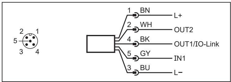
1: L+
2: OUT2: switching output
3: L-
4: OUT1: switching output or IO-Link
5: IN1: laser on / off
6.1 PNP/NPN selection
Pins 2 and 4 can be switched between PNP and NPN logic.
The setting cannot be made for individual pins, but applies to all pins.
| PNP | NPN |
1: L+
2: OUT2: switching output
3: L-
4: OUT1: switching output or IO-Link
5: IN1: laser on / off
7 Operating and display elements
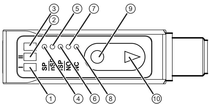
| 1: | 1x LED yellow | Switching status OUT1 |
| 2: | 1x LED yellow | Switching status OUT2 |
| 3: | 1x LED green | Status LED |
| 4: | 1x LED white | [SP] = Switch point for hysteresis function |
| 5: | 1x LED white | [nSP] = Near switch point for window function |
| 6: | 1x LED white | [fSP] = Far switch point for window function |
| 7: | 1x LED white | [NO] = Normally open function |
| 8: | 1x LED white | [NC] = Normally closed function |
| 9: | Programming button [●] | Set button |
| 10: | Programming button [▼] | Navigation button |
7.1 LED states
| LED behaviour | Description | Action | ||
| OUT 1 | Status LED | OUT 2 | ||
| (0753) | (0470) | (0968) | Status LED is green | Device is connected to the voltage supply and ready for operation |
| (0800) | (0700) | (0800) | Status LED is green, OUT 1 is yellow | Device OK, switching output OUT 1 active |
| (0814) | (0550) | (0977) | Status LED is green, OUT 2 is yellow | Device OK, switching output OUT 2 active |
| (0874) | (0540) | (0972) | Status LED flashing red (1Hz), OUT 1 flashing yellow (4 Hz) | Short circuit OUT 1 Troubleshooting (→ ☐ 24) |
| (0422) | (0470) | (0743) | Status LED flashing red (1Hz), OUT 2 flashing yellow (4 Hz) | Short circuit OUT 2 Troubleshooting (→ ☐ 24) |
| (0400) | (0890) | (0772) | Status LED flashing red (1 Hz) | Error (correctable by the operator) Troubleshooting (→ ☐ 24) |
| (0482) | (0461) | (0285) | Status LED is red | Serious error▶ Contact ifm support. Contact at www.ifm.com |
| (0420) | (0211) | (0184) | Status LED is green, OUT1 and OUT2 (8 Hz) flashing | [Find me] Function |
7.2 LED states of the parameters
| LED behaviour | Description | Action | ||
| SP | nSP/fSP | NO/NC | ||
| All LEDs are off | The device is in the Run mode. | |||
| [SP] and [NO]/[NC] are white | Device is in Info mode. Hysteresis function is activated. Sensor operates as normally open or normally closed. | |||
| [nSP]/[fSP] and [NO]/[NC] are white | Device is in Info mode. Window function is activated. Sensor operates as normally open or normally closed. | |||
8 Set-up

The sensor needs a warm-up period of ≥ 20 min. The performance parameters specified in the data sheet only apply after this warm-up period.
After power on, the device is put into operation. After approx. 3 s the device is ready for operation.
On delivery, the parameters are set to the factory setting ( → Factory setting ☐ 26).
The device can also be configured using suitable IO-Link parameter setting software.
9 Parameter setting
The sensor can be configured via the [●] and [▼] buttons as well as using IO-Link.
Internally, the device remains in the operating mode during parameter setting. It continues its monitoring function with the existing parameters until the change has been completed.

The output logic (PNP/NPN) and the switching output [OUT2] can only be set via IO-Link. On delivery, the output logic PNP is set.
The selection of the control signal with which the laser is switched off is also made via IO-Link.
9.1 Hysteresis function
The selected switch point [SP] is the set point. The reset point is automatically set behind the selected switch point [SP] by the sensor. The nominal distance between set point and reset point is the hysteresis, which can be set via IO-Link.
9.1.1 Parameter setting of the switch point via the device buttons
▶ Press the button [●] to exit the Run mode.
▷ LED for [SP] is white.
▶ Position the object.
▶ Press and hold the [●] button for 2 seconds to teach [SP].
▷ LED for [SP] flashes twice (50 Hz).
▷ Sensor returns to the Run mode.
9.1.2 Parameter setting of the switch point via IO-Link
Single point mode ( → ☐ 21)
▶ Call up [Parameters] > [SSC1.1 / SSC1.2].
▶ Select [SSC1.1 Config. Mode / SSC1.2 Config. Mode].
▶ Set [Single point].
▶ Select [SSC1.1 Param. SP1 / SSC1.2 Param. SP1].
▶ Enter [SP1] in mm.

The switch point can also be taught via teach commands (system commands).
▶ Call up [Parameters] > [Teach].
▶ Select [TI Select].
▶ Select [SSC1.1] or [SSC1.2]. (Depending on which output is to be taught.)
▶ Select the corresponding system commands and carry out the teaching process by clicking on the buttons.
9.1.3 Hysteresis function via IO-Link
The hysteresis keeps the switching state of the output stable if the measured value varies about the sensing range. The selected switch point [SP] is the set point. The reset point is automatically set behind the selected switch point [SP] by the sensor. The hysteresis is the nominal distance between the set and reset points.
The hysteresis can be set via IO-Link.
▶ Call up [Parameters] > [SSC1.1 / SSC1.2].
▶ Select [SSC1.1 Config. Hyst / SSC1.2 Config. Hyst].
▶ Enter the hysteresis in mm.
9.2 Window function
It is possible to define a window for the object recognition for each of the two outputs (OUT1 / OUT2).

The switch points for the window can be set independently of each other and in any order. To teach a clearly defined window, both switch points must always be taught.

If [nSP] > [fSP] has been taught, the device will automatically invert the values. The condition nSP = fSP (in IO-Link SP1 = SP2) is not permitted. A minimum distance must be entered.
OMH550: minimum distance 2 mm
OMH552: minimum distance 7 mm
OMH554: minimum distance 10 mm
9.2.1 Parameter setting via the device buttons
▶ Press the button [●] to exit the Run mode.
▷ LED for [SP] is white.
▶ Use [▼] to navigate to [nSP] (near switch point) or [fSP] (far switch point).
▷ LED for [nSP] / [fSP] is white.
▶ Position the object.
▶ Press and hold the [●] button for 2 seconds to teach [nSP] / [fSP].
▷ LED for [nSP] / [fSP] flashes twice (50 Hz).
▷ Sensor returns to the Run mode.
9.2.2 Parameter setting via IO-Link
Window mode ( → ☐ 22)
▶ Call up [Parameters] > [SSC1.1 / SSC1.2].
▶ Select [SSC1.1 Config. Mode / SSC1.2 Config. Mode].
▶ Set [Window].
▶ Select [SSC1.1 Param. SP1 / SSC1.2 Param. SP1].
▶ Enter [SP1] in mm.
▶ Select [SSC1.1 Param. SP2 / SSC1.2 Param. SP2].
▶ Enter [SP2] in mm.

The window can also be taught via teach commands (system commands).
▶ Call up [Parameters] > [Teach].
▶ Select [TI Select].
▶ Select [SSC1.1] or [SSC1.2]. (Depending on which output is to be taught.)
▶ Select the corresponding system commands and carry out the teaching process by clicking on the buttons.
9.3 Two-point function (Two point mode)
It is possible to define a switching area for the object recognition for each of the two outputs (OUT1 / OUT2). There is no hysteresis.
The function can only be set via IO-Link.

The switching points for the two-point function (Two point mode) can be set independently of each other. Both switching points always have to be set.
9.3.1 Parameter setting via IO-Link
Two point mode ( → ☐ 23)
▶ Select [Parameter] > [SSC1.1 / SSC1.2].
▶ Select [SSC1.1 Config. Mode / SSC1.2 Config. Mode].
▶ Set [Two point].
▶ Select [SSC1.1 Param. SP1 / SSC1.2 Param. SP1].
▶ Enter [SP1] in mm.
▶ Select [SSC1.1 Param. SP2 / SSC1.2 Param. SP2].
▶ Enter [SP2] in mm.

The switching area can also be taught via teach commands (system commands).
▶ Call up [Parameters] > [Teach].
▶ Select [TI Select].
▶ Select [SSC1.1] or [SSC1.2]. (Depending on which output is to be taught.)
▶ Select the corresponding system commands and carry out the teaching process by clicking on the buttons.
9.4 Activating OUT2
9.4.1 Parameter setting via IO-Link
▶ Call up [Parameters] > [Output configuration].
▶ Select [ou2].
▶ Set [SSC1.2].
9.5 Output logic (PNP/NPN)
Set the switching logic for all inputs and outputs.
9.5.1 Parameter setting via IO-Link
▶ Call up [Parameters] > [Basic settings].
▶ Select [P-n].
▶ Set [PnP] (positive switching) or [nPn] (negative switching).
9.6 Output function
9.6.1 Parameter setting via the device buttons
▶ Press the button [●] to exit the Run mode.
▷ LED for [SP] is white.
▶ Use [▼] to navigate to [NO] (normally open) or [NC] (normally closed).
▷ LED for [NO] / [NC] is white.
▶ Press and hold [●] for 2 seconds to set [NO] / [NC].
▷ LED for [NO] / [NC] flashes twice (50 Hz).
▷ Sensor returns to the Run mode.
9.6.2 Parameter setting via IO-Link
▶ Call up [Parameters] > [SSC1.1] (OUT1) / [SSC1.2] (OUT2).
▶ Select [SSC1.1 Config. Logic] (OUT1) / [SSC1.2 Config. Logic] (OUT2).
▶ Set [High active] (normally open) or [Low active] (normally closed).
9.7 Lock / unlock the device
9.7.1 Parameter setting via the device buttons
Locking:
▶ Press and hold [●] and [▼] simultaneously for 10 seconds.
▷ Green status LED flashes (1 Hz).
▷ After 10 seconds, the green status LED flashes twice (50 Hz).
▷ The sensor is locked and returns to the Run mode.
Unlocking:
▶ Press and hold [●] and [▼] simultaneously for 10 seconds.
▷ Green status LED flashes (1 Hz).
▷ After 10 seconds, the green status LED flashes twice (50 Hz).
▷ The sensor is unlocked and returns to the Run mode.

Indication of device locking:
▶ Press [●] or [▼].
▷ Green status LED goes out for 0.5 seconds.
▷ The device changes to Run mode and the green status LED is again lit permanently.
9.7.2 Parameter setting via IO-Link
▶ Call up [Parameters] > [Display settings].
▶ Select [Loc].
▶ Set [Loc] for locking and [uLoc] for unlocking.

Indication of device locking:
▶ Press [●] or [▼].
▷ Green status LED goes out for 0.5 seconds.
▷ The device changes to Run mode and the green status LED is again lit permanently.
9.8 Indication of current setting (Info mode)
▶ Press [▼] to change to the Info mode.
▷ LEDs are on for 2 seconds depending on the setting at [NO] / [NC] and at [SP] or [nSP] / [fSP] to indicate whether the hysteresis or window function is set.
▷ Sensor returns to the Run mode.
9.9 Reset to factory setting
9.9.1 Reset via device buttons
▶ Disconnect the voltage supply.
▶ Press and hold [▼] and restore the voltage supply.
▶ Release [▼] press [●].
▷ Green status LED flashes twice confirming reset to factory setting.
9.9.2 Reset via IO-Link
▶ Call up [Parameters] > [Basic settings].
▶ Click on the system command [Reset application] or [Back-to-box].
▷ The device is reset according to the selected reset method.

The two system commands reset the device in a different way.
[Reset application]: The parameters of the technology-specific application are set to default values. The identification parameters remain unchanged. An upload to the data memory of the master is carried out, if activated in the port configuration of the master.
[Back-to-box]: The parameters of the device are set to the factory settings and communication is blocked until the next time the device is switched off and on. Note: Disconnect the device directly from the master port!
9.10 Additional parameter settings via IO-Link
9.10.1 Switch-on delay
A switch-on delay can be set for both switching outputs (0...10s).
▶ Call up [Parameters] > [SSC1.1 / SSC1.2].
▶ Select [SSC1.1 / SSC1.2 Switch-on delay].
▶ Enter a switch-on delay between 0...10s.

To set a switch-on delay for [SSC1.2], this output must first be activated.
9.10.2 Switch-off delay
A switch-off delay can be set for both switching outputs (0...10s).
▶ Call up [Parameters] > [SSC1.1 / SSC1.2].
▶ Select [SSC1.1 / SSC1.2 Switch-off delay].
▶ Enter a switch-off delay between 0...10s.

To set a switch-off delay for [SSC1.2], this output must first be activated.
9.10.3 Filter
Setting the filter property in relation to the detection speed.
4 options can be selected.
• [HIGH] (Slow detection, precision)
• [MEdi] (Standard)
• [LOW] (Average detection, filtering of individual interference pulses)
• [OFF] (Fast detection, without filtering)
▶ Call up [Parameters] > [Signal].
▶ Select [FILT].
▶ Set one of the options.
9.10.4 Transmitter configuration
Setting to activate and deactivate the transmitter.
4 options can be selected.
• [OFF / Off] (permanently off)
• [ON / On] (permanently on)
- [On_ExtActive / Switch on with external signal active] (via input IN1 at pin 5)
• [PDOut / Controlled by PDOut] (via IO-Link communication PDOut)
▶ Select [Parameter] > [Signal].
▶ Select [Transmitte configuration].
▶ Set one of the options.

The operating state of the device can be changed with the help of control data via IO-Link (PDOut).
In case of a communication interruption (COMLOST), the device remains in the last operating state set by valid control data (PDOut).
9.10.5 Switching counter
Counts the number of detected objects.
▶ Call up [Parameters] > [Digital Output 1 / Digital Output 2].
▶ Select [SSC1.1 counter / SSC1.2 counter].
▶ Read the counter value.
The counter can be reset via the system command [Reset counter to zero]. The command resets all counters.
▶ Call up [Parameters] > [Counter configuration].
▶ Click on the system command [Reset counter to zero].
▷ All counters (switching counters and memory Lo / Hi) are reset.
9.10.6 Operating modes
Setting the evaluation speed.
3 options can be selected:
• [Standard]
• [Power]
• [Speed]
▶ Call up [Parameters] > [Basic settings].
▶ Select [ModE].
▶ Set one of the options.
| Operating mode | Speed | Object colour (black) |
| [Standard] | ++ | ++ |
| [Power] | + | +++ |
| [Speed] | +++ | + |
The table provides a preliminary assessment of different applications and the respective operating modes. The rating scale ranges from “+” (less suitable) to “+++” (very suitable).
10 Setting
10.1 Setting the range via IO-Link

With "Switchpoint Logic = 1", "ON" and "OFF" can be seen reversed in the graphics.
10.1.1 Single point mode
SSC active: PDV ≥ SP1
SSC inactive: PDV ≤ SP1 + H
10.1.1.1 Single point mode to smart sensor profile

Normally open:
(switch point logic = 0)
SP1
Switch-on point
SP1 + H
Switch-off point
10.1.1.2 Single point mode to smart sensor profile - Two value teach

Normally open:
(switch point logic = 0)
SP1 = √TP1*TP2
Switch-on point
SP1 + H
Switch-off point
10.1.1.3 Single-point mode - position

Normally open:
(Switch point logic = 0)
SP1
Switch-on point
SP2 + H
Switch-off point
10.1.1.4 Background suppression

Normally open: (switch point logic = 0)
SP1 = teach - 2*H Switch-on point
SP1 + H Switch-off point
SP: Switch point
H: Hysteresis
TP: Teach point
B: Background suppression
SSC: Switching
SignalChannel
PDV: Process
DataVariable
10.1.2 Window mode

Normally open: (switch point logic = 0)
SP1 Switch-on point
SP1 + H Switch-off point
SP2

- 1 PRELIMINARY NOTE
- 1.1 SYMBOLS USED
- 1.2 WARNINGS
- 2 SAFETY INSTRUCTIONS
- 3 INTENDED USE
- 4 FUNCTION
- 4.1 OUTPUT FUNCTION HYSTERESIS
- 4.2 OUTPUT FUNCTION WINDOW
- 5 INSTALLATION
- 5.1 INSTALLATION CONDITIONS
- 5.2 MOUNTING ACCESSORIES
- 5.3 INSTALLATION INSTRUCTIONS
- 5.3.1 AVOIDANCE OF SOILING AND AMBIENT LIGHT
- 5.3.2 AVOIDANCE OF MUTUAL INTERFERENCE
- 5.3.3 SENSOR ALIGNMENT FOR A MOVING OBJECT
- 6 ELECTRICAL CONNECTION
- 6.1 PNP/NPN SELECTION
- 7 OPERATING AND DISPLAY ELEMENTS
- 7.1 LED STATES
- 7.2 LED STATES OF THE PARAMETERS
- 8 SET-UP
- 9 PARAMETER SETTING
- 9.1 HYSTERESIS FUNCTION
- 9.1.1 PARAMETER SETTING OF THE SWITCH POINT VIA THE DEVICE BUTTONS
- 9.1.2 PARAMETER SETTING OF THE SWITCH POINT VIA IO-LINK
- 9.2 WINDOW FUNCTION
- 9.2.1 PARAMETER SETTING VIA THE DEVICE BUTTONS
- 9.2.2 PARAMETER SETTING VIA IO-LINK
- 9.3 TWO-POINT FUNCTION (TWO POINT MODE)
- 9.3.1 PARAMETER SETTING VIA IO-LINK
- 9.4 ACTIVATING OUT2
- 9.4.1 PARAMETER SETTING VIA IO-LINK
- 9.5 OUTPUT LOGIC (PNP/NPN)
- 9.5.1 PARAMETER SETTING VIA IO-LINK
- 9.6 OUTPUT FUNCTION
- 9.7 LOCK / UNLOCK THE DEVICE
- 9.7.1 PARAMETER SETTING VIA THE DEVICE BUTTONS
- 9.7.2 PARAMETER SETTING VIA IO-LINK
- 9.8 INDICATION OF CURRENT SETTING (INFO MODE)
- 10 SETTING
- 10.1 SETTING THE RANGE VIA IO-LINK
- 10.1.1 SINGLE POINT MODE
- 10.1.1.1 SINGLE POINT MODE TO SMART SENSOR PROFILE
- 10.1.1.2 SINGLE POINT MODE TO SMART SENSOR PROFILE - TWO VALUE TEACH
- 10.1.1.3 SINGLE-POINT MODE - POSITION
- 10.1.1.4 BACKGROUND SUPPRESSION
- 10.1.2 WINDOW MODE
Brand : IFM
Model : OMH551
Category : Rangefinder