SF211A - Detector IFM - Free user manual and instructions
Find the device manual for free SF211A IFM in PDF.
User questions about SF211A IFM
0 question about this device. Answer the ones you know or ask your own.
Ask a new question about this device
Download the instructions for your Detector in PDF format for free! Find your manual SF211A - IFM and take your electronic device back in hand. On this page are published all the documents necessary for the use of your device. SF211A by IFM.
USER MANUAL SF211A IFM
natural_image
Abstract icon of a factory building with smokestacks, no text or symbols present| BetriebsanleitungStrömungssensoren |
| Operating instructionsFlow sensors |
| Notice d‘utilisationSondes de débit |
| Istruzioni per l‘usoSensori di flusso |
| Instrucciones de usoSensores de caudal |
| BruksanvisningFlödesgivare |
| SF*1*A |
DE
UK
FR
IT
ES
SE


BG български
According to the ATEX directive 94/9/EC (ATEX) the original operating instructions and a translation of 1. these operating instructions into the language or languages of the EU user country must be provided when a unit or protective system is put into operation within the member countries of the European Union (EU).
If no operating instructions or EC declaration of conformity is supplied with this product in the language 2. of the EU user country, these can be requested from your dealer (see delivery note) or manufacturer (see cover sheet / back).
Only qualified personnel is allowed to set up the product. Furthermore, we expressly point out that any 3. liability is excluded resulting from putting the unit into operation without the corresponding operating instructions in the language of the EU user country.
ES Español
SN2301, SN2302, SN2303, SN2304, SR2301
- Anschlussbelegung
flowchart
graph TD
    A["SF*1*A"] --> B["BN"]
    A --> C["BK"]
    A --> D["GY"]
    A --> E["WH"]
    A --> F["BU"]
    B --> G["VS2000 Exi"]
    C --> G
    D --> G
    E --> G
    F --> G
- Prozessanschlüsse
$$ \mathrm{SF11} ^ {} \mathrm{A} = \mathrm{M12SF21} ^ {} \mathrm{A} = \mathrm{G} ^ {1 / 4} \mathrm{SF31} ^ {*} \mathrm{A} = \mathrm{G} ^ {1 / 2} $$
Operating instructions (safety-related part ATEX)
Remarks for safe use in hazardous areas
Functions and features
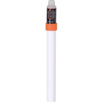
In conjunction with the control monitor VS2000 Exi the flow sensor monitors flows in liquid and gaseous media and detects whether a preset flow value is reached (= medium is flowing) or not (= medium is not flowing) and provides a switching signal.
- Use in hazardous areas according to the classification
II 1/2G (group II, category 1/2 G, apparatus for gas atmosphere). - The flow sensors are suitable for installation in the partition 1/2G.
- The requirements of the standards EN 60079-0, EN 60079-11, EN 60079-26 are met.
EC type test certificate
DMT 03 ATEX E090 X
- Marking

II 1/2G Ex ia IIC T4 Ga/Gb Ta = -20 ... +60°C
Installation / Set-up
The units must only be installed, connected and set up by qualified staff. The qualified staff must have knowledge of protection classes, regulations and provisions for apparatus in hazardous areas.
Check whether the classification (see "Marking" above and marking on the unit) is suitable for the application.
The flow sensors are only allowed to be connected to the specified control monitors type VS2000 Exi type of protection intrinsic safety II (1) G [Ex ia] IIC
with the EC type test certificate PTB 01 ATEX 2075. Take the connection values into account.
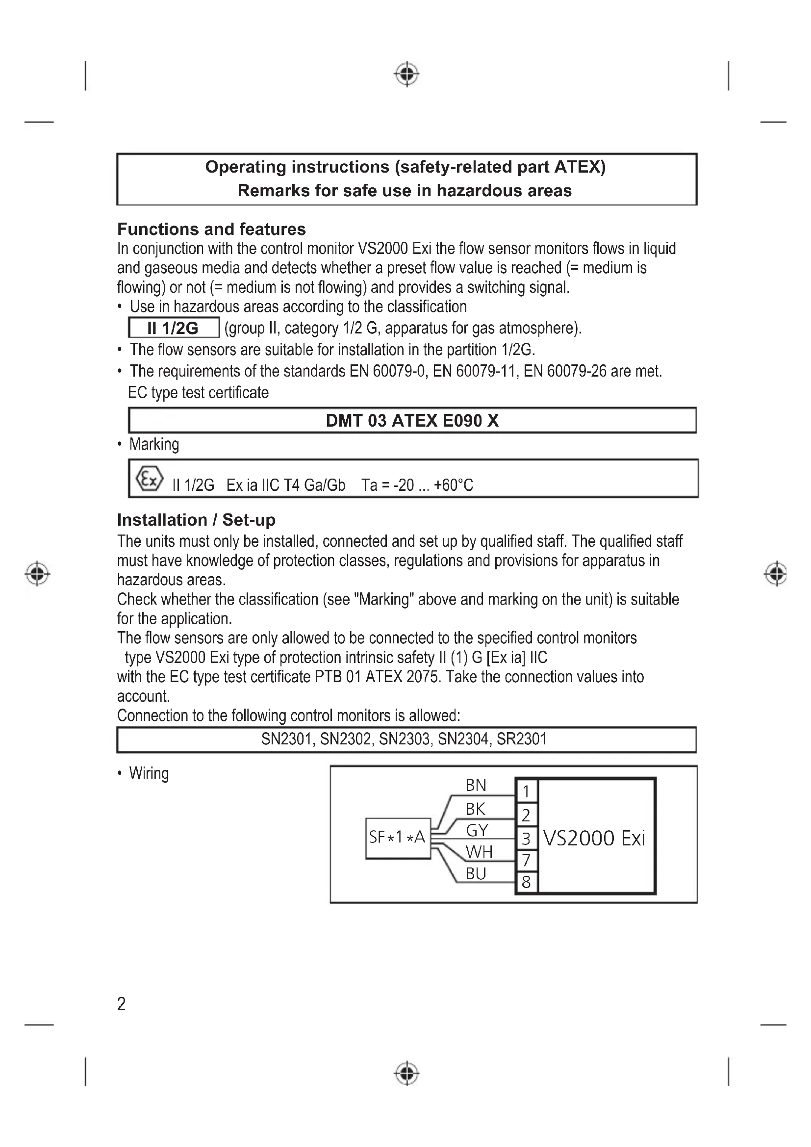
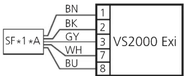
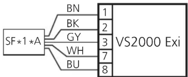
Connection to the following control monitors is allowed:
SN2301, SN2302, SN2303, SN2304, SR2301
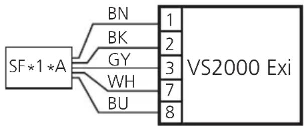
- Wiring
flowchart
graph LR
    A["SF*1 *A"] --> B["BN"]
    A --> C["BK"]
    A --> D["GY"]
    A --> E["WH"]
    A --> F["BU"]
    B --> G["VS2000 Exi"]
    C --> G
    D --> G
    E --> G
    F --> G
- Process connections
$$ \mathrm{SF} 1 1 ^ {} \mathrm{A} = \mathrm{M} 1 2 \mathrm{SF} 2 1 ^ {} \mathrm{A} = \mathrm{G} ^ {1 / 4} \mathrm{SF} 3 1 ^ {*} \mathrm{A} = \mathrm{G} ^ {1 / 2} $$
- Permissible operating temperature range at the mounting location and maximum temperature range of the medium:
$$ - 2 0 \dots + 6 0 ^ {\circ} \mathrm{C} $$
- In principle, the type test according to 94/9/EC only takes atmospheric conditions (0.8...1.1bar and mixture temperatures of -20...+60°C) into account. For pressures outside these ranges use must be assessed and approved by the user.
- Maximum effective internal inductance (Li) and capacitance (Ci) of the flow sensors (the values apply to potted cables):
| Article no. Cable | length Internal inductance | (total) in μH | Internal capacitance (total) in nF |
| SF311A 6 m 6 | 1.2 | ||
| SF211A 6 m 6 | 1.2 | ||
| SF111A 6 m 6 | 1.2 | ||
| SF*1*A xx m 1*) | 2*) |
UK
Articles with cable/variants of cable units SF*1*A:
For variants of cable units with potted cables of a different length the values of the cable must be taken into account.
0.68 H (Li) / 95 pF (Ci) per metre of potted cable.
*1) Thus the maximum effective internal inductance of the unit results in:
Li = 6 μH + cable length in (m) × 0.68 μH
*2) Thus the maximum effective internal capacitance of the unit results in:
Ci = 1.2 nF + cable length in (m) x 0.095 nF.
Installation remarks / Installation
- Adhere to the relevant national regulations and provisions.
- The relevant installation regulations (e.g. EN 60079-14) must be adhered to.
- Avoid electrostatic charging on plastic parts and cables.
- Protect the units efficiently against damage.
- The cable must be firmly laid and protected efficiently against damage.
- Steps must be taken to ensure the equalisation of potential of metal parts (housing and fixing material).
- The unit is suitable for installation in the partition 1/2 G. Please take the special conditions for safe operation into account.
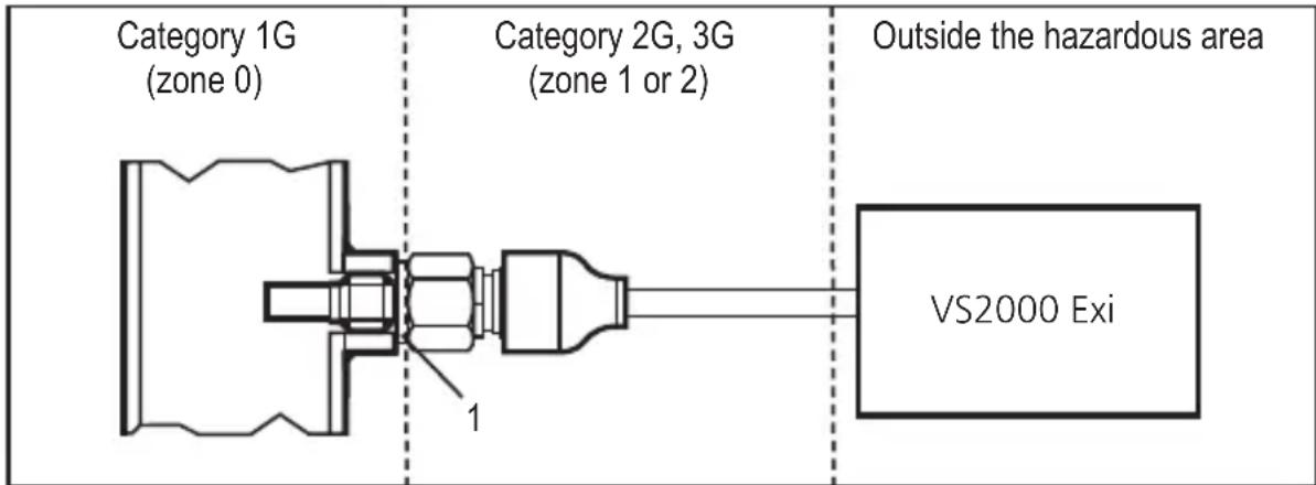
Special conditions for safe operation
The unit is suited for installation in the partition (category 1/2G); e.g. tank, pipes. Sealing at the transition (category 1/2G) must be rated according to the conditions of the corresponding application. The part of the sensor housing of corrosion-resistant steel (316S12) which reaches into the category 1G (zone 0) has a wall thickness of minimum 0.6 mm due to function. In the application the user must ensure that in this area risks, e.g. due to aggressive media or mechanical hazards, are excluded.
Mounting in pipes or tanks:
text_image
Category 1G (zone 0) Category 2G, 3G (zone 1 or 2) Outside the hazardous area VS2000 Exi1: seal
Maintenance / Repair
- The flow sensor has to be included in the recurrent pressure test of the tank or pipe.
- The unit must not be modified nor can it be repaired. In case of a fault please contact the manufacturer.
- If needed, you can obtain data sheets or EC type test certificates from the manufacturer (see cover sheet / back).
Scale drawings and notes for the correct installation are given in the separately enclosed part of the operating instructions ("Operating instructions / Installation instructions").
UK


SN2301, SN2302, SN2303, SN2304, SR2301
SN2301, SN2302, SN2303, SN2304, SR2301
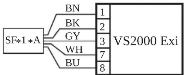
- Cablaggio
flowchart
graph LR
    A["SF*1*A"] --> B["BN"]
    A --> C["BK"]
    A --> D["GY"]
    A --> E["WH"]
    A --> F["BU"]
    B --> G["VS2000 Exi"]
    C --> G
    D --> G
    E --> G
    F --> G
    G --> H["1"]
    G --> I["2"]
    G --> J["3"]
    G --> K["7"]
    G --> L["8"]
SN2301, SN2302, SN2303, SN2304, SR2301
- Conexionado
flowchart
graph TD
    A["SF*1*A"] --> B["BN"]
    A --> C["BK"]
    A --> D["GY"]
    A --> E["WH"]
    A --> F["BU"]
    B --> G["VS2000 Exi"]
    C --> G
    D --> G
    E --> G
    F --> G
SN2301, SN2302, SN2303, SN2304, SR2301
- Anslutning

flowchart
graph LR
    A["SF*1*A"] --> B["BN"]
    A --> C["BK"]
    A --> D["GY"]
    A --> E["WH"]
    A --> F["BU"]
    B --> G["VS2000 Exi"]
    C --> G
    D --> G
    E --> G
    F --> G
    G --> H["1"]
    G --> I["2"]
    G --> J["3"]
    G --> K["7"]
    G --> L["8"]
- Processanslutningar
$$ \mathrm{SF} 1 1 ^ {} \mathrm{A} = \mathrm{M} 1 2 \mathrm{SF} 2 1 ^ {} \mathrm{A} = \mathrm{G} ^ {1 / 4} \mathrm{SF} 3 1 ^ {*} \mathrm{A} = \mathrm{G} ^ {1 / 2} $$