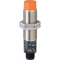
DI6001 - Monitor IFM - Free user manual and instructions
Find the device manual for free DI6001 IFM in PDF.


User questions about DI6001 IFM
0 question about this device. Answer the ones you know or ask your own.
Ask a new question about this device
Download the instructions for your Monitor in PDF format for free! Find your manual DI6001 - IFM and take your electronic device back in hand. On this page are published all the documents necessary for the use of your device. DI6001 by IFM.
USER MANUAL DI6001 IFM
CE
Installation instructions
Compact speed monitor M18
ecomot200®
DI6001

1 Preliminary note
1.1 Symbols used
▶ Instruction
→ Cross-reference

Non-compliance can result in malfunctions or interference.
Information
Supplementary note
2 Safety instructions
The unit must be connected by a qualified electrician. Observe the national and international regulations for the installation of electrical equipment.
3 Functions and features
The unit detects without contact if a set rotational speed is not reached and signals this by means of a switching signal. The pulse output enables the external evaluation of the damping pulses.
▶ Nominal sensing range (Sn) and operating voltage see type label.
4 Installation


▶ Fix the unit by means of a mounting device and secure it by means of the nuts provided so that it cannot work loose.
▶ Adhere to the above dimensions to ensure a correct function.
Non flush mountable.
5 Electrical connection


- L+
- pulse output (the pulse sequence corresponds to the damping frequency)
- L-
- switching output (adjustable)
6 Operating and display elements
| View | LED | Status | Meaning | |
 | PWR | green | ON | operating voltage OK |
| OUT | yellow | ON | output is switched | |
| DMP | green | pulse | damping pulse | |
| 1 Hz2 Hzdouble flash | time periods during the setting operation (→ 8 setting operation) | |||
| OUT + DMP | yellow green | flashing alternately | Settings locked or setting not accepted | |
1: LEDs
2: set button
7 Adjustable parameters
| Parameter | Value range | Preset teach value | |
| SP | switch point(= teach value x 0.8) | 3...6000 pulses/min | 100 pulses/min |
| tAÜ | Start-up delay | 0...15 s | 10 s |
| Output | output function | normally open / normally closed | NO (output closed when speed > switch point) |
| Key | locking | on/off | off |
8 Setting operation

→◎ = press the button and keep it pressed
◎ = release the button = setting stored
→ ≡ = release the button and press n times (0 times = 0 s, 1 time = 1 s, etc.)
The setting operation is divided into time periods (steps) with a duration of approx. 3 and 5 seconds. The time periods are indicated by different flashing frequencies of the DMP LED. The corresponding setting is stored within a time period by releasing the pressed button.
| Step | Setting | To store: |
| 1 | set the switch point | release the button |
| 2 | set the start-up delay | release the button press the button n times, wait 5 s after the last push of the button |
| 3 | change the output function (NO - NC, NC - NO) | release the button |
| 4 | lock or unlock the settings | release the button |
▶ Press the button with a blunt object (e.g. pen).
9 Operation
The operation is maintenance-free. Ensure the following for a correct function:
▶ Keep the sensing face and the open space free of metal deposits and foreign bodies.
▶ Do not operate units with high field intensity (e.g. walkie-talkies) at close range to the speed monitor.

Brand : IFM
Model : DI6001
Category : Monitor