
DL2003 - Monitor IFM - Free user manual and instructions
Find the device manual for free DL2003 IFM in PDF.

| Product type | Analog threshold programmable controller (monitor) |
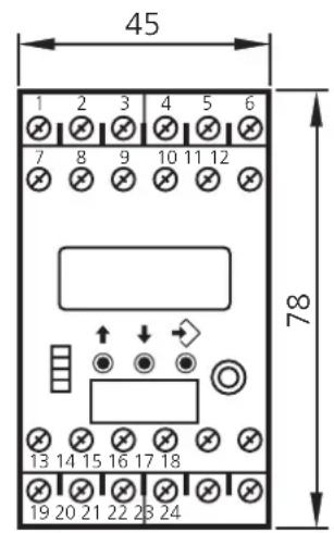
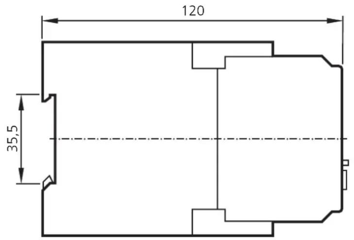
| Dimensions (H x W x D) | 78 x 45 x 120 mm |
| Weight | 500 g |
| Power supply | 110-240 V AC/DC or 24 V DC (external SELV) |
| Display | LCD 7/14 segments, 5 digits + 3 alphanumeric digits |
| Analog inputs | 2 x 0/4-20 mA (detectors or transmitters) |
| Relay outputs | 2 changeover contacts, 6 A/250 V AC |
| Transistor outputs | 2 x PNP, 12-30 V DC / max. 15 mA |
| Analog output | 0/4-20 mA (PWM), max load 500 Ω |
| Enclosure / terminal protection | IP50 / IP20 |
| Ambient temperature | -25 °C to +60 °C |
| Mounting | DIN rail or base |
| Main functions | Limit value monitoring (flow, pressure, temperature, level), comparator mode (A-B, A+B), teach function, delay, memorization |
| Programming | Via front buttons, system and application parameters |
| Maintenance and cleaning | Clean with a dry cloth after power off |
| Repairability | Repair only by the manufacturer |
| Safety | Mounting and connection by electrician, compliance with EMC and low voltage standards |
| Marking | CE according to EN 61010, EMC 89/336/EEC |
Frequently Asked Questions - DL2003 IFM
User questions about DL2003 IFM
0 question about this device. Answer the ones you know or ask your own.
Ask a new question about this device
Download the instructions for your Monitor in PDF format for free! Find your manual DL2003 - IFM and take your electronic device back in hand. On this page are published all the documents necessary for the use of your device. DL2003 by IFM.
USER MANUAL DL2003 IFM
IN1 Input 1 (type) 4-20 mA 0-20 mA
IN2 Input 2 (type) 4-20 mA 0-20 mA
●INP Input 1/2 (type) 4-20 mA 0-20 mA

F02 Function Output 2
S01 Store Output 1
S02 Store Output 2

FS1 Function Signal Evaluation Input 1
FS2 Function Signal Evaluation Input 2

DM1 Dimension Input 1
DM2 Dimension Input 2
DIM Dimension Input 1/2

A03 Analog Output 3
□ 0-20 mA □ 4-20 mA
■ Applikationsparameter / Application parameters / Paramètres d'application
SP1 Switch Point Output 1 6.0
SP2 Switch Point Output 2 18.0

HY1 Hysteresis Output 1
HY2 Hysteresis Output 2
ST1 Start-Up-Delay Output 1
ST2 Start-Up-Delay Output 2

DT1 Delay Time Output 1
DT2 Delay Time Output 2

FT1 Fleeting Time Output 1
FT2 Fleeting Time Output 2

AE3 Analog End Output 3
AS3 Analog Start Output 3

□ = Voreinstellung
= factory setting
= réglage en usine
Name Datun
The operating instructions
... apply to all monitors type AL-3.
... are for authorised persons according to the EMC and low voltage directives.
... are part of the unit. They contain information about the correct handling of the product. Read them before use to familiarise yourself with operating conditions, installation and operation. Follow the safety instructions.
Contents
- Safety instructions.... page 23
- Function and features ..... page 24
- Operating and indicating elements..... page 26
- Mounting ...... page 27
- Electrical connection
Terminal connection .... page 27
Voltage supply ...... page 27
Connection of the sensors and transmitters . . . . . . . . . . . . page 28
Input reset 1/2 ...... page 28
Input release 1/2 . . . . . . . . . . . . . . . . . . . . . . . . . . . . . . . . . . . . . . . . . . . page 28
Load circuit relay output (Out1/2)..... page 29
Load circuit transistor (Out1/2) . . . . . . . . . . . . . . . . . . . . . . . . . page 29
Analogue output (Out3)....page 29 - Signal monitoring ..... page 29
- Navigation and parameter description ..... page 30
System parameters ..... page 32
Application parameters . . . . . . . . . . . . . . . . . . . . . . . . . . . . . . . . page 34 - Programming ..... page 35
Programming example DT2 (Delay Time, output 2) ..... page 35
Notes on programming . . . . . . . . . . . . . . . . . . . . . . . . . . . . . . . . . . . . . . . . . . page 36 - Setting example Monitoring of limit values and differential pressure ..... page 38
- Technical data..... page 39
Input circuit diagram . . . . . . . . . . . . . . . . . . . . . . . . . . . . . . . . . . . . . . . page 40 - Scale drawing . . . . . . . . . . . . . . . . . . . . . . . . . . . . . . . . . . . . . . . . . . . . . page 40
- Maintenance, repair, disposal . . . . . . . . . . . . . . . . . . . . . . . . . . . page 40
Parameter list (unit settings ☒). . . . . . . . . . . . . . . . . . . . . . . . . . . . . . . . . . . . . . . page 41
Overview parameters...... page 61
Appendix
1. Safety instructions
Follow the operating instructions. Non-observance of the instructions, operation which is not in accordance with use as prescribed below, wrong installation or handling can affect the safety of people and the plant.
The installation and connection must comply with the applicable national and international standards. Responsibility lies with the person installing the unit.
The unit must be installed, connected and put into operation by a qualified electrician as
• during the installation dangerous contact voltage occurs and
- the safe function of the unit and the plant is only guaranteed when installation is correctly carried out.
Disconnect the unit externally before handling it. Also disconnect any independently supplied relay load circuits.
Be careful when handling the connected unit. Due to the protection rating IP 20 this is only allowed by qualified staff.
The design of the unit corresponds to the protection class II except for the terminal blocks. Protection against accidental contact (safety from finger-touch to IP20) for qualified staff is only guaranteed if the terminal screw has been completely screwed in. For the correct operation the unit must be mounted in a housing (protection rating IP40 or higher) which can only be opened using a tool or in a closed control cabinet.
If the unit has an external 24 V DC supply, this voltage must be generated and supplied externally according to the requirements for safe extra-low voltage (SELV) since without further measures this voltage is supplied near the operating elements and at the terminals for the supply of connected pulse pick-ups.
The wiring of all signals concerning the SELV circuit of the unit must also meet the SELV criteria (safe extra-low voltage, safe electrical separation from other circuits).
If the externally supplied or internally generated SELV voltage is externally grounded, the responsibility lies with the user in accordance with the applicable national installation regulations. All statements in the operating instructions refer to the unit which is not grounded with respect to the SELV voltage.
It is not allowed to supply external voltage to the terminals for the pulse pick-up supply and the analogue output.
The consumption of current which exceeds the value given in the technical data is not allowed.
An external main switch must be installed for the unit which can switch off the unit and all related circuits. This main switch must be clearly assigned to the unit.
According to the technical specifications below the unit can be operated in a wide operating temperature range. Because of the additional internal heating the operating elements and the housing walls can have high perceptible temperatures when touched in hot environments.
In case of malfunction of the unit or uncertainties please contact the manufacturer. Tampering with the unit can seriously affect the safety of people and equipment. This is not permitted and leads to an exclusion of liability and warranty.
2. Function and features
The Monitor AL-3 is a programmable, analogue threshold relay for the evaluation of physical values derived from analogue standard signals. The setting possibilities of the various parameters ensure that the function of the unit is variable within a great range of values and can thus be adapted to the individual application.
Applications are for example:
- Limit monitoring of flow, pressure, temperature, or level,
• monitoring of the difference between inflow and return flow or
• monitoring of differential pressure.
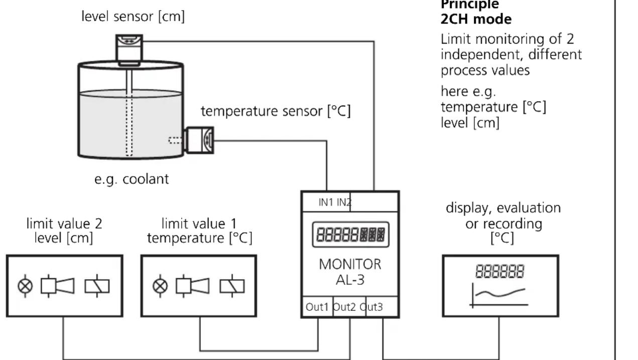
flowchart
graph TD
    A["level sensor [cm"]] --> B["temperature sensor [°C"]]
    B --> C["e.g. coolant"]
    C --> D["limit value 1 temperature [°C"]]
    D --> E["limit value 2 level [cm"]]
    E --> F["IN1 IN2 MONITOR AL-3"]
    F --> G["Out1 Out2 Out3"]
    G --> H["display, evaluation or recording [°C"]]
The analogue current signals at both inputs can be scaled, displayed and monitored independently of each other. The start and end values of the current signal can be assigned any numerical value – corresponding to the measuring range of the sensor (e.g. 4...20 mA = 0...25 [bar]).
The monitor compares the actual signal values with the set limit values and switches the assigned outputs depending on the set parameter values and functions. The analogue output provides the input signal IN 1 unchanged or scaled for further use.
In the comparator mode the monitor AL-3 forms the difference or the total from the two input signals (IN 1-IN 2, IN 1+IN 2). The differential or the total value can be displayed, evaluated, compared with the set limit values, and provided as analogue signal. The outputs switch according to the set parameter values and functions.
The teach function enables the assignment of an actual signal value to a switch point and detection of the value range of the analogue output.
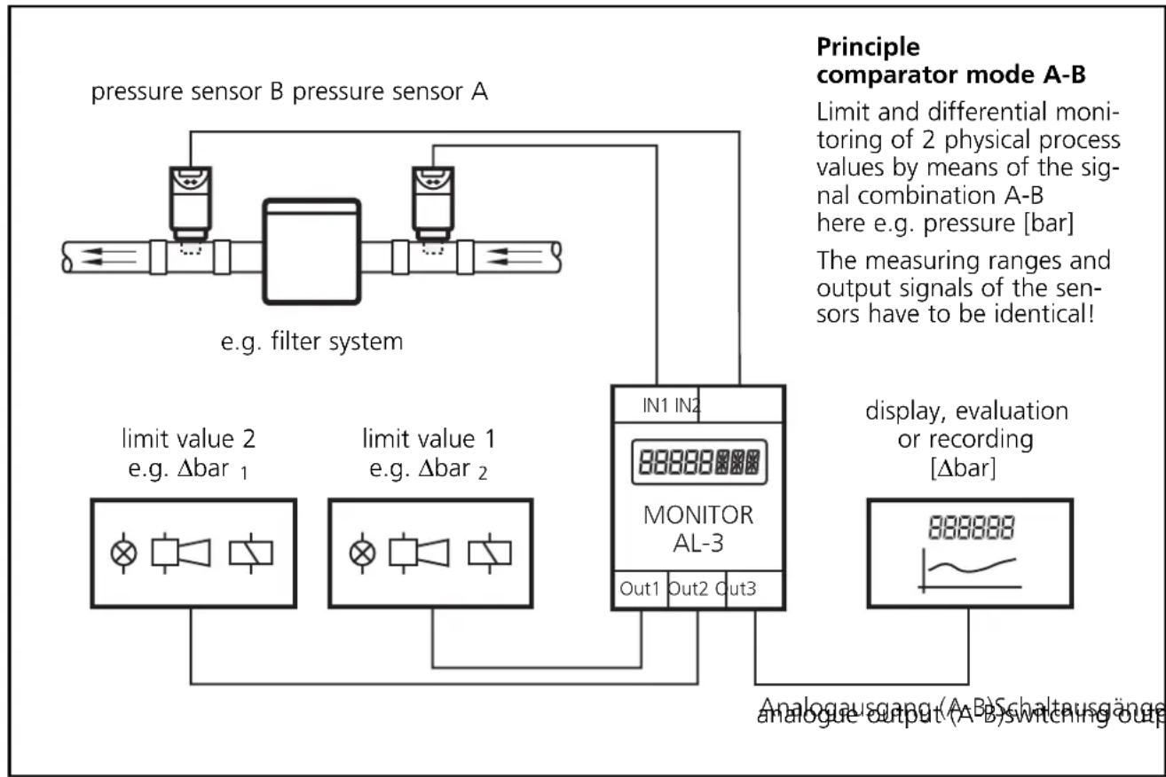
flowchart
graph TD
    A["pressure sensor B pressure sensor A"] --> B["e.g. filter system"]
    B --> C["limit value 2 e.g. Δbar 1"]
    B --> D["limit value 1 e.g. Δbar 2"]
    C --> E["MONITOR AL-3"]
    D --> E
    E --> F["In1 In2"]
    E --> G["Out1 Out2 Out3"]
    H["Principle comparator mode A-B"] --> I["Limit and differential monitoring of 2 physical process values by means of the signal combination A-B here e.g. pressure [bar"]]
    H --> J["The measuring ranges and output signals of the sensors have to be identical!"]
    K["display, evaluation or recording [Δbar"]] --> L["888888"]
    M["Analogausgang (A-B) Schaltausgänge analogue output (A-B) Switching out"] --> L
The AL-3 monitor only has one channel. By means of an electrical connection of the output of two or several units to achieve a redundant circuit, they can also be used for safety tasks. The applicable technical standards must be adhered to.
3. Operating and indicating elements
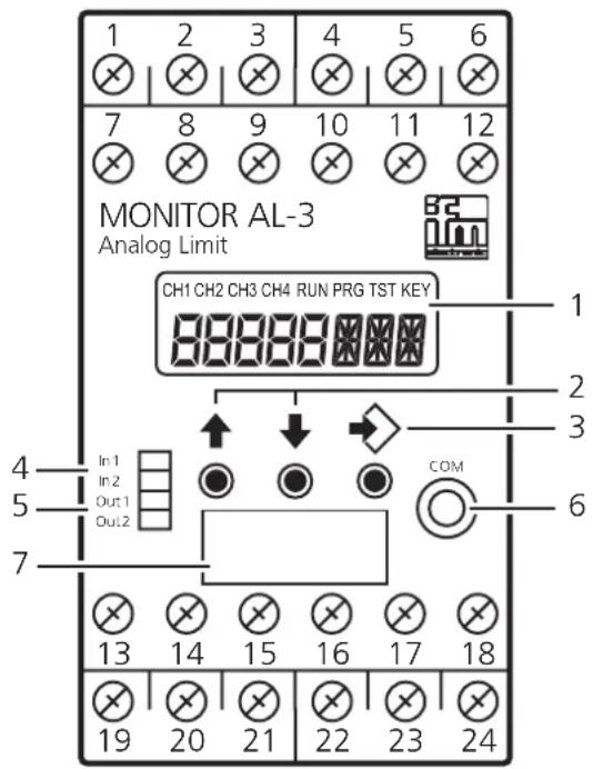
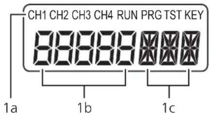
| 1 Display (7/14-segment) |
| 1a Indicators for input channels and operating modesCH1...CH4 Input channels (here: CH1 and CH2)RUN Run mode (normal operating mode)PRG Programming mode (setting of the parameter values)TST Test mode (only optional)KEY Status of the unit (locking) |
| 1b Display Actual values and parameter values (5-digit, numerical)Input signal: 0.0...20.0 mA (max. 23.0 mA)Scaled values: -9999 (999.9)...+9999 (999.9)Outside the valid value ranges the display shows "----". |
| 1c Display Parameter abbreviation and units (3-digit, alphanumeric) |
| 2 pushbuttons / selection of the actual value display, parameter selection, setting of the parameter values |
| 3 pushbutton Selection of the operating mode, acknowledgement of the parameter value, front reset |
| 4 LED In1/2 (yellow) Input signals (LEDs active, if In1/2 > 0,1 mA)On: Signal in the operating rangeSlowly flashing: Signal in the warning rangeQuickly flashing: Signal in the error range |
| 5 LED Out1/2 (green) Switching state of the outputOff: The output is not switched (relay de-energised, transistor blocked)On: The output is switched (relay energised, transistor switched)Slowly flashing: The delay time is effective for the output. The output switches when the delay time has elapsed and the trigger event is still present (parameter DTx, Delay Time)Quickly flashing: The output is kept latched (parameter SOx, Store Output) |
| 6 Interface (without function) |
| 7 Panel for labelling |
4. Mounting
Mount the unit on a DIN rail or by means of a mounting base. Leave enough space between the unit and the top and bottom of the control cabinet to enable air circulation to avoid excessive heating.
Take the internal heating of all units into account when mounting several units side by side. The environmental conditions must be observed for every unit.
Mounting of the sensors:
Adhere to the mounting instructions of the manufacturer.
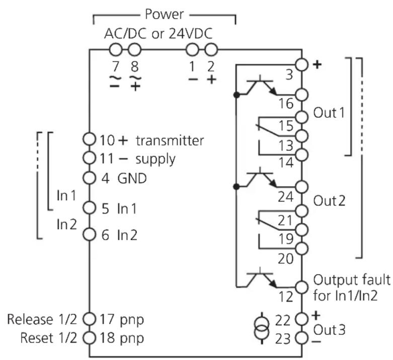
5. Electrical connection
Terminal connection
DL2003:
110...240 V AC/DC
If the transmitters are supplied via an external 24 V DC power supply the wiring indicated on the following page is to be observed.
An electrical separation between monitor and transmitter supply only exists for AC monitor supply (terminals 7/8).
Voltage supply (power)
It is only allowed to operate the unit via one of the possible voltage connections, i.e. either terminals 7/8, AC/DC or terminals 1/2, 24 V DC.
The terminals 1/2 of the 24 V DC supply are directly connected to the terminals of the sensor supply. The SELV criteria must therefore be met for the DC supply (safe extra-low voltage, circuit electrically separated from other circuits, not grounded).
The supply cable must be protected externally according to the cross-section used (max. 16 A).
The device shall be supplied from an isolating source and protected by an overcurrent protection device such that the limited voltage circuit requirements in accordance with UL 508 are met.
If the DC circuit is to be grounded (e.g. due to national regulations), the respective directives must be adhered to (safe extra-low voltage, circuit electrically separated from other circuits).
If the unit is AC supplied (DW2003), the low voltage provided for the sensor supply meets the SELV criteria according to EN 61010, overvoltage category II, soiling degree 2.
To guarantee safe functioning, signal cables (sensors, transistor outputs, input signals) and load cables (power supply, relay outputs) should be laid separately.
If necessary, use a screened cable.
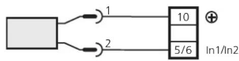
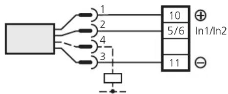
Connection of the sensors and transmitters
2-wire
power supply via AL-3
flowchart
graph TD
    A[" "] -->|1| B["10"]
    A -->|2| C["5/6"]
    D["+"] --> B
    E["In1/In2"] --> B
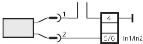
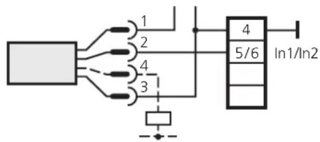
3 or 4 wires
power supply via AL-3
external power supply external power supply
flowchart
graph TD
    A["Input Line 1"] --> B["Block 4"]
    C["Input Line 2"] --> B
    B --> D["In1/In2"]
The examples refer to ifm sensors!
Adhere to the information of the manufacturer.
Terminal 10 can be used for the transmitter supply, triggering of the reset/release input and supply of the transistor outputs.
Input reset 1/2 (external reset)
A pulse (+24 V DC) on terminal 18 resets the relay state latched in case of a fault if the latching function is active (parameter SOx).
Pressing the pushbuttons continuously does not influence the monitoring function.
Input release 1/2 (external release of the start-up delay)
A signal (+24 V DC) on terminal 17 keeps outputs 1 and 2 in the same state as with the active start-up delay. If the signal is no longer provided, the set start-up delay (STx) starts. In case of a stored fault the signal on terminal 17 is only effective after a reset has been made.
Load circuit relay output (Out 1/2)
To prevent excessive wear and to comply with the EMC regulations interference suppression of the contacts is required for switching inductive loads.
If the relay is used to switch very small currents (e.g. PLC inputs), considerable contact resistance can arise. In this case use the transistor output.
Load circuit transistor (Out 1/2)
The transistor outputs need an external voltage of 24 V DC at terminal 3. This voltage can be taken from the unit via terminal 10.
The reference point (GND) of the external power supply must be connected to terminal 1 of the monitor, otherwise no switching operation is possible.
The device shall be supplied from an isolating source and protected by an overcurrent protection device such that the limited voltage circuit requirements in accordance with UL 508 are met.
Analogue output, PWM (Out 3)
The analogue output is not electrically separated from the sensor/transmitter supply and from the 24V DC supply voltage. No dangerous contact circuits must be connected to the analogue output.
6. Signal monitoring
The measuring range of the input signals is divided into the operating range, the warning range and the fault range. For signal monitoring it is useful to connect a sensor/transmitter with a 4...20 mA output signal.
If an input signal is in the warning or fault range, this is indicated by flashing of the yellow input LED In1 or In2. The transistor output "output fault" (terminal 12) is blocked as soon as a signal is in the fault range.
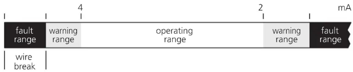
The transitions fault range warning range are equipped with a hysteresis: < 3.6mA and >3.7mA / >22mA and < 21.9mA
The transitions operating range warning range (< 4 mA, > 20 mA) are equipped with a delay time t_v of 500 ms.
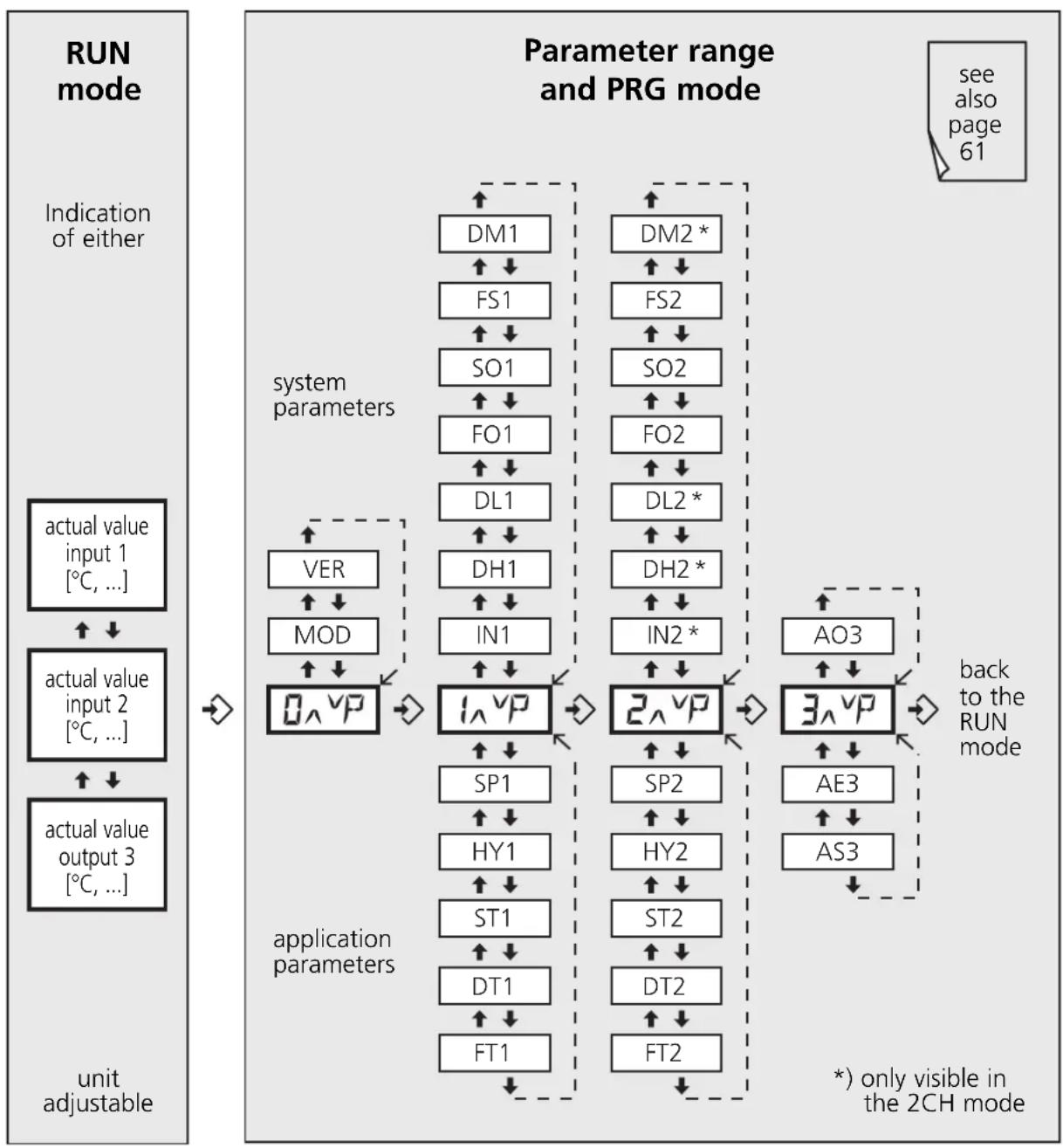
7. Navigation and parameter description
The -buttons and the -button are used for the selection, entry of values and acknowledgement within the parameters arranged in columns.
The parameters above _A^vP and _A^vR are general system para-
meters. They are normally set only once during commissioning depending on the machines or systems to be monitored.
The parameters below these entries are application parameters. They can be set or changed more often.
1CH and 2CH mode
flowchart
graph TD
    A["run mode"] --> B["Indication of either"]
    B --> C["actual value input 1 [°C, ..."]]
    C --> D["↑ ↓"]
    D --> E["actual value input 2 [°C, ..."]]
    E --> F["↑ ↓"]
    F --> G["actual value output 3 [°C, ..."]]
    G --> H/unit adjustable
    H --> I["0 ∧ VP"]
    I --> J["system parameters"]
    J --> K["DM1 ↑ ↓"]
    J --> L["FS1 ↑ ↓"]
    J --> M["SO1 ↑ ↓"]
    J --> N["FO1 ↑ ↓"]
    J --> O["DL1 ↑ ↓"]
    J --> P["DH1 ↑ ↓"]
    J --> Q["IN1 ↑ ↓"]
    J --> R["1 ∧ VP"]
    R --> S["application parameters"]
    S --> T["SP1 ↑ ↓"]
    S --> U["HY1 ↑ ↓"]
    S --> V["ST1 ↑ ↓"]
    S --> W["DT1 ↑ ↓"]
    S --> X["FT1 ↑ ↓"]
    S --> Y["DM2 * ↑ ↓"]
    S --> Z["FS2 ↑ ↓"]
    S --> AA["SO2 ↑ ↓"]
    S --> AB["FO2 ↑ ↓"]
    S --> AC["DL2 * ↑ ↓"]
    S --> AD["DH2 * ↑ ↓"]
    S --> AE["IN2 * ↑ ↓"]
    S --> AF["2 ∧ VP"]
    AF --> AG["AO3 ↑ ↓"]
    AF --> AH["3 ∧ VP"]
    AH --> AI["back to the RUN mode"]
    AI --> AJ["* only visible in the 2CH mode"]
Different system parameters are available depending on the selected mode (MOD):
- 1CH and 2CH mode; to detect, display and monitor 1 or 2 independent and possibly different process values (see page 24, Principle).
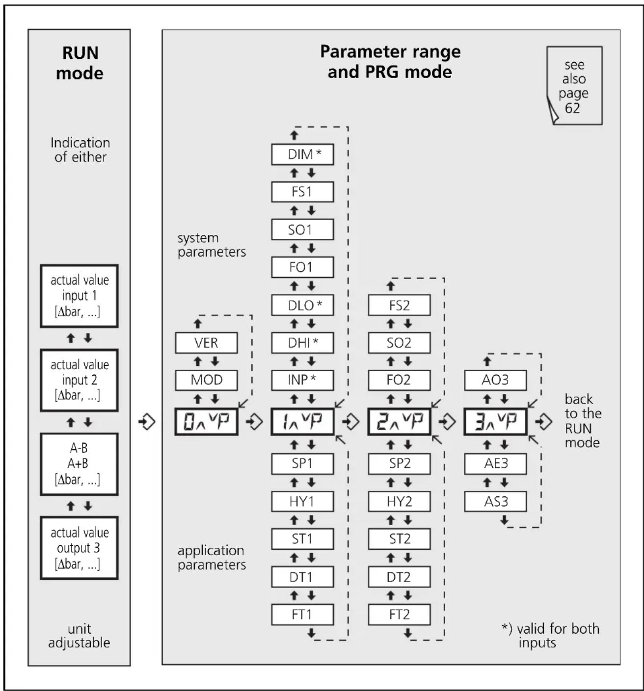
- Comparator mode; for differential monitoring or formation of the total of 2 physically identical process values (see page 25, Principle).
Comparator mode (A-B, A+B)
flowchart
graph TD
    A["run mode"] --> B["Indication of either"]
    B --> C["actual value input 1 [Δbar, ..."]]
    C --> D["↓"]
    D --> E["actual value input 2 [Δbar, ..."]]
    E --> F["↑"]
    F --> G["A-B"]
    G --> H["MOD"]
    H --> I["↓"]
    I --> J["0^VP"]
    J --> K["system parameters"]
    K --> L["DIM*"]
    L --> M["↑"]
    M --> N["FS1"]
    N --> O["↑"]
    O --> P["SO1"]
    P --> Q["↑"]
    Q --> R["FO1"]
    R --> S["↑"]
    S --> T["DLO*"]
    T --> U["↑"]
    U --> V["DHI*"]
    V --> W["↑"]
    W --> X["INP*"]
    X --> Y["↑"]
    Y --> Z["1^VP"]
    Z --> AA["application parameters"]
    AA --> AB["SP1"]
    AB --> AC["↑"]
    AC --> AD["HY1"]
    AD --> AE["↑"]
    AE --> AF["ST1"]
    AF --> AG["↑"]
    AG --> AH["DT1"]
    AH --> AI["↑"]
    AI --> AJ["FT1"]
    AJ --> AK["application parameters"]
    AK --> AL["FS2"]
    AL --> AM["↑"]
    AM --> AN["SO2"]
    AN --> AO["↑"]
    AO --> AP["FO2"]
    AP --> AQ["↑"]
    AQ --> AR["2^VP"]
    AR --> AS["application parameters"]
    AS --> AT["SP2"]
    AT --> AU["↑"]
    AU --> AV["HY2"]
    AV --> AW["↑"]
    AW --> AX["ST2"]
    AX --> AY["↑"]
    AY --> AZ["DT2"]
    AZ --> BA["↑"]
    BA --> BB["FT2"]
    BB --> BC["application parameters"]
    BC --> BD["AO3"]
    BD --> BE["↑"]
    BE --> BF["3^VP"]
    BF --> BG["application parameters"]
    BG --> BH["AE3"]
    BH --> BI["↑"]
    BI --> BJ["AS3"]
    BJ --> BK["application parameters"]
    BK --> BL["*"] valid for both inputs
System parameters
Parameter Description, values, default value
Parameter list ☒ see page 41
| MOD Mode (operating mode) | ||
| 1CH • Single channel2CH • Dual channel | Monitors an analogue signal at input 1 with 2 limit values (outputs 1 and 2). Simultaneously monitors two different analogue signals at inputs 1 and 2 with one limit value each (In1 → output 1; In2 → output 2). The analogue output reacts to the signal at input 1. | |
| A-B • Comparator (subtraction mode In1-In2)AuB • Comparator (addition mode In1+In2) | Forms the difference of 2 analogue signals and monitors the differential value with 2 limit values (outputs 1 and 2). The analogue output reacts to the differential signal. Forms the total of 2 analogue signals and monitors this with 2 limit values (outputs 1 and 2). The analogue output reacts to the signal of the total. | |
| • Values: 1CH, 2CH, A-b, Aub• Default value: 1CH (single channel) | ||
| VER Software Version | ||
| The installed software version is displayed (5-digit number with abbreviation VCO) | ||
| INx, INP Input (input signal) | ||
| 4-20 Selection of the input signal in the 1CH/2CH or A-B/A+B mode0-20 • Values: 4-20, 0-20 [mA]• Default value: 4...20 mA | ||
| DHx, DHI Display High (end value of the measuring range) | ||
| Corresponds to the actual measuring value at 20 mA• Values: 1CH/2CH mode: -9999.0...9999.0; A-B/A+B mode: -4999.0...4999.0• Default value: 20.0 | ||
| DLx, DLO | Display Low (start value of the measuring range) | |
| Corresponds to the actual measuring value at 0 or 4 mA• Values: 1CH/2CH mode: -9999.0...9999.0; A-B/A+B mode: -4999.0...4999.0• Default value: 4.0 | ||
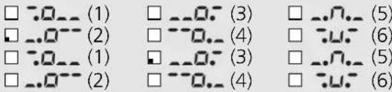
| FOx Function Output (switching function of the outputs) | ||
| -0-- (1) | Relay energises (transistor output conductive) when the current value is below the switch point. Switches back at SP + HY. | 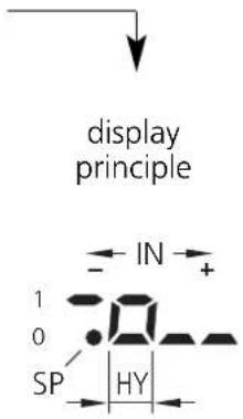 |
| -0-- (2) | Relay de-energises (transistor output blocked) when the current value is below the switch point. Switches back at SP + HY. | |
| -0-- (3) | Relay energises (transistor output conductive) when the current value is above the switch point. Switches back at SP - HY. | |
| -0-- (4) | Relay de-energises (transistor output blocked) when the current value is above the switch point. Switches back at SP - HY. | |
| -0-- (5) | Relay is energised (transistor output conductive) within a window (acceptable range). | |
| -0-- (6) | Relay is de-energised (transistor output blocked) within a window range. | |
With functions 5 and 6 a measuring range above and below the switch point SPx is defined in connection with the parameter HYx (hysteresis).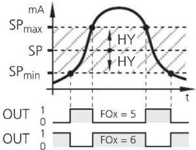 SP = _max + SP_min2 HY = - SP_minSP × 100 [%] SP = _max + SP_min2 HY = - SP_minSP × 100 [%] | ||
| Values: ..C(1), ..(2), ..(3), ..(4), ..(5), (6)Default value: FO1 = (2) FO2 = (3) ..0. | ||
| SOx Store Output (latching function output 1/2) | ||
| OFF Inactive Front Active with front reset (-button>3 s) FuE Active with front and external resetWhen the latching function is active the respective output does not switch back automatically but must be reset.Values: OFF, Front, FuEDefault value: OFF (latching function inactive) | ||
| FSx Function Signal Evaluation (signal and wire monitoring) | ||
| OFF Inactive on Active | ||
Switching characteristics of the relay outputs with inactive and active parameter FSx Example switching functions 1 and 2: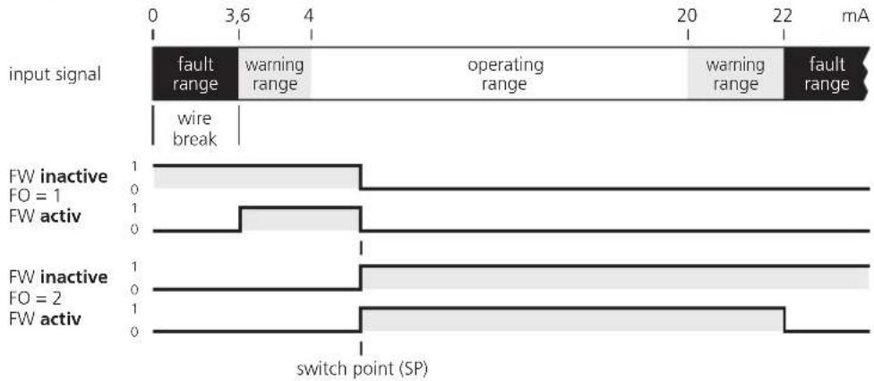 | ||
| Values: OFF, onDefault value: OFF (signal and wire monitoring inactive) | ||
| DMx,DIM Dimension (unit) | ||
| Values: °C, bar, lit, mA, no technical unitDefault value: mA | ||
| AO3 | Analogue Out3 (analogue output) | |
| 4-200-20 | Current range of the analogue signalValues: 4-20, 0-20 [mA]Default value: 0...20 mA | |
Application parameters
Parameter Description, values, default value
| SPx | Switch Point (switch point output 1/2) Teach function (see page 36) |
| Value at which output 1 or 2 changes its switching state according to the function FOx. Values: -9999 (-999.9)...+9999 (+999.9)Default value: SP1 = 6.0, SP2 = 18.0 | |
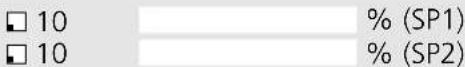
| HYx | Hysteresis (hysteresis for output 1/2) |
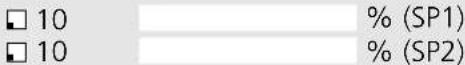
Distance between switch point and reset point. Prevents a possible chattering of the switching output. The hysteresis is indicated in % of the switch point SPx.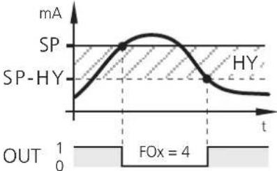 Values: 0.1...100.0 [%]Default value: 10 % Values: 0.1...100.0 [%]Default value: 10 % | |
| STx Start-Up-Delay (start-up delay output 1/2) | |
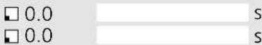
| To suppress error messages when a plant is started.When the device is switched on or when the 24 V signal is removed from the reset input, the respective output is kept in the "good" state independent of the measured value.Values: 0,0...1000,0 [s]Default value: 0,0 s (start-up delay inactive) | |
| DTx Delay Time (delay time output 1/2) | |
| Enables delayed switching of the respective output.In case of a value >0.0 s the output only switches if the current value is above or below the switch point for more than the time set here.Values: 0,0...1000,0 [s]Default value: 0,0 s (no delay time) | |
| FTx Fleeting Time (fleeting function output 1/2) | |
| In case of an event, the respective output changes its state during the set time and then switches back to the initial state.Values: 0,0...1000,0 [s]Default value: 0,0 s (fleeting time inactive) | |
| AE3 | Analogue End (end value analogue output) Teach function (see page 36) |
| Numerical value at which the output signal is to be 20 mA.Values: -9999 (-999.9)...+9999 (+999.9)Default value: 20.0 | |
| AS3 | Analogue Start (start value analogue output) Teach function (see page 36) |
| Numerical value at which the output signal is to be 0 or 4 mA.Values: -9999 (-999.9)...+9999 (+999.9)Default value: 0.0 | |
8. Programming

If programming takes place during operation, dangerous contact voltage can occur. Therefore ensure that programming is done by a qualified electrician.

Parameter changes during operation, especially changes of the switching function or the teach in of the parameters SP1, SP2, AE3 or AS3 can lead to malfunction in the plant. In case of doubt stop the plant and change the parameters manually.
Programming consists of 6 steps:
- Change from the RUN mode to the parameter range 0...3 pushbutton
- Selection of the requested parameter (MOD, IN1, etc) pushbuttons /
- Change to the PRG mode pushbutton
- Setting or changing the parameter value pushbuttons /
- Acknowledgement of the set parameter value pushbutton (> 3 s)
- Return to the RUN mode pushbutton (> 3 s)

Programming example DT2 (Delay Time, output 2)
| Operation Display | |
| Change from the RUN mode to the parameter range (here 2) | |
| Briefly press the pushbutton three times.The 2nd parameter range is displayed ... | 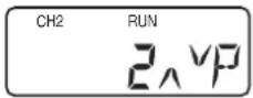 |
| Selection of the requested parameter (here DT2) | |
| Press the pushbuttonuntil the parameter DT2 is displayedwith the current set value (here default value 0.0) ... | 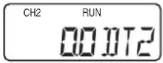 |
| Change to the PRG mode | |
| Briefly press the pushbutton once.The unit is in the programming mode.PRG indicator visible, parameter abbreviation flashes ... | 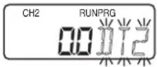 |
| Setting or changing the parameter value | |
| Press the pushbuttonuntil the requested parameter value is indicated ...(also see "Numerical entries" on the following page) | 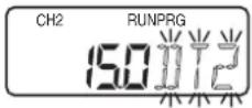 |
| Acknowledgement of the set parameter value | |
| Press the pushbutton until the parameter abbreviation no longerflashes and the indicator PRG has disappeared.The new parameter value is indicated and effective ... | 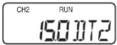 |
| Return to the RUN mode | |
| Press the pushbutton for about 3 s or wait forthe Time-Out function (approx. 15 s).The unit is again in the RUN mode, the current value is indicated ... | 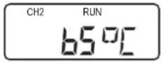 |
Notes on programming
RUN mode
During programming the unit internally remains in the RUN mode! (RUN indicator visible).
This means that until a new value is acknowledged with the pushbutton the unit carries out its monitoring function on the basis of the previously set parameters and switches the relay and transistor outputs accordingly.
Note:
The monitoring function of the monitor is deactivated by continuously pressing the ➕ button in the RUN mode. The deactivation is effective as long as the pushbutton is pressed.
Teach function
SP1 Switch point Output 1 (switch point output 1)
SP2 Switch point Output 2 (switch point output 2)
AE3 Analogue End Output 3 (end value analogue output)
AS3 Analogue Start Output 3 (start value analogue output)
In addition to the numerical entry the above-mentioned parameters can also be set by the teach function. In the programming mode this function enables to measure and display the current input signal and to assign the selected parameter to it.
To teach the actual measured value the same programming steps as for the "normal" programming are done first.
- Change from RUN mode to parameter range 1,2 or 3 pushbutton
- Selection of the requested parameter (SP1, SP2, AE3 or AS3) pushbuttons ↑/↓
- Change to the PRG mode pushbutton
(PRG indicator visible, parameter abbreviation flashes)


The teaching is started by pressing the ↗buttons simultaneously in the PRG mode. The current measured value is displayed and can be changed by the ↑ or ↓ button on request.
As for the numerical programming the value is stored by pressing the button until the parameter abbreviation no longer flashes and the PRG indicator has disappeared.
Time Out Function
If during programming no pushbutton is pressed for approx. 15 s, this is seen as a cancellation.
Parameter changes which are not acknowledged with the pushbutton are rejected. The previously set parameter value is restored and remains effective for the monitoring functions.
Numerical entries
Press the ↑ or pushbutton and hold it.
The smallest decade becomes active and is counted up or down depending on the selected pushbutton (e.g. 1, 2, 3, .... 0). Then comes the next decade, etc.
As soon as the pushbutton is released, the active decade flashes. It is set by pressing the or pushbutton several times. The preceding decade then flashes and can be set.
Factory reset
The factory default values can be restored by pressing the and pushbuttons simultaneously during power on. All entered parameter values are lost.
KEY function
The unit can be locked to prevent incorrect entries.
- Locking:
Press the pushbuttons ♦ simultaneously and hold them. The KEY indicator flashes. Release the pushbuttons when the KEY indicator is continuously indicated.
- Unlocking:
Press the pushbuttons ♦ simultaneously and hold them. The KEY indicator flashes. Release the pushbuttons when the KEY indicator is no longer indicated.
9. Setting example
Monitoring of limit values and differential pressure
(see also principle comparator mode, page 25)
| Application | |||
| Monitoring of a filter system by recording the measured pressure values before and behind the filter. | |||
| System requirements Example values | |||
Max. possible system pressure 21 barOperating pressure (nominal pressure) 20 barMin. permissible operating pressure 5 barMeasuring range of the sensors/transmitters 0...25 barAnalogue output of the sensors/transmitters 4...20 mAThe measuring ranges and output signalsof the sensors/transmitters have to be identical! 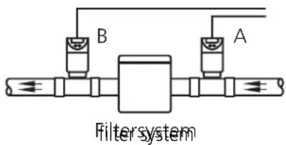 | |||
| Monitor parameters Setting (value) Description | |||
| MOD Mode A-B Differential monitoring [Δ bar] | |||
| INx Input (type) 4-20 Analogue outputs of the sensors/transmitters | |||
| DHI Display High 25 Max. measured value of the sensor/transmitter | |||
| DLO Display Low 0 Min. measured value of the sensor/transmitter | |||
| FO1 Function Output 1 --0..(4) Relay 1 de-energises when current value is above SP1 (switches back at SP1 - HY1) | |||
| FO2 Function Output 2 --0..(4) Relay 2 de-energises when current value is above SP1 (switches back at SP2 - HY2) | |||
| SP1 Switch point Output 1 5 Differential pressure Δ bar 1 (limit value 1) | |||
| SP2 Switch point Output 2 15 Differential pressure Δ bar 2 (limit value 2) | |||
| HY1/2 Hysteresis for SP1/2 10 Reset point [% of SPx] | |||
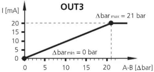
| AO3 Analogue Output 3 (type) 0-20 0...20 mA signal for Δbar evaluation | |||
| AE3 Analogue End Output 3 21 Max. possible differential pressure (Δ bar max) | |||
| AS3 Analogue Start Output 3 0 Min. possible differential pressure (Δ bar min) | |||
| Output characteristics (OUT1...3) | |||
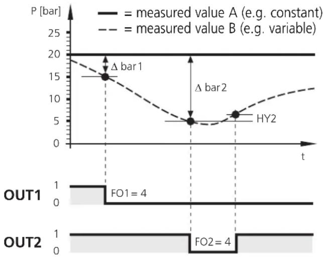  |
10. Technical data
| DL2003 | |
| Supply voltage AC/DC 110...240 V | (50...60 Hz) |
| Supply voltage DC 27 V (typ. 24 V) | |
| Voltage tolerance -20...+10 % | |
| Power consumption 8 VA / 5 W | |
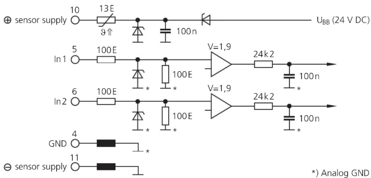
| Analogue inputs 2 x 0/4...20 mA for sensors or transmittersAuxiliary voltage 24 V DC, 150 mA, short circuit protectedMeasuring range 0...22.5 mAAccuracy ± 0.25 %Resolution 12 bitInternal resistance 200 ΩSampling rate 2 msInput frequency max. 200 Hz | |
| Relay outputs 1 changeover contact each, potential-freeSwitching capacity 6 A (250 V AC), B300, R300Switching timeCycles | 10...20 ms (energising), 30...40 ms (de-energising) >10^7 (without load) 3 × 10^5 (250 V AC, 4 A, ohmic resistance) |
| Transistor outputsSwitching voltage / current | PNP switching, externally supplied, short-circuit protected12...30 V DC (±20%) / max. 15 mA |
| Analogue outputAccuracyCurrentLoad | Pulse-width modulated (PWM)< ± 1 %0/4...20 mA (max. 20,5 mA)max. 500 Ω |
| Reset-/Release inputsExternal auxiliary voltageCurrent consumptionSwitch point for PNP circuit | 24 V DCTyp. 2.5 mA11 V / 6 mA |
| Device dataDimensions (H x W x D)WeightProtection housing / terminalsConnection | housing for DIN rail mounting; plastic78 x 45 x 120 mm500 gIP 50 / IP 2023 dual-chamber terminals; 2 x 2.5 mm^2 (AWG 14) |
| DisplayDisplayLEDs | LC display, 7/14-segment2 x yellow (input signals)2 x green (switching outputs) |
| Environmental conditionsOperating / storage temperatureTemperature driftAir pressureRelative air humidityMaximum operating altitude | -25...60°C / -25...80°C< ± 100 ppm/K75...106 kPamax. 75 % (35°C)2000 m above MSL |
| CE mark | according to EN 61010 (1993); +A2 (1995; EMV 89/336/EWG)EN50081-1; EN 61000-6-2 |
Typical input circuit
11. Scale drawing
12. Maintenance, repair, disposal
In case of correct use no maintenance and repair measures are necessary. Only the manufacturer is allowed to repair the unit.
If necessary, the unit can be cleaned by qualified personnel using a dry cloth after disconnecting all connected circuits.
After use dispose of the unit in an environmentally friendly way in accordance with the applicable national regulations.
Parameterliste / Parameter list / Table des paramètres ✗
■MOD Mode 1CH A-B


■ Systemparameter / System parameters / Paramètres de système
IN1 Input 1 (type) 4-20 mA 0-20 mA
IN2 Input 2 (type) 4-20 mA 0-20 mA
●INP Input 1/2 (type) 4-20 mA 0-20 mA

F02 Function Output 2

S01 Store Output 1
S02 Store Output 2

FS1 Function Signal Evaluation Input 1
FS2 Function Signal Evaluation Input 2

DM1 Dimension Input 1
DM2 Dimension Input 2
DIM Dimension Input 1/2

A03 Analog Output 3
□ 0-20 mA □ 4-20 mA
■ Applikationsparameter / Application parameters / Paramètres d'application
SP1 Switch Point Output 1 6.0
SP2 Switch Point Output 2 18.0

HY1 Hysteresis Output 1
HY2 Hysteresis Output 2
ST1 Start-Up-Delay Output 1
ST2 Start-Up-Delay Output 2
DT1 Delay Time Output 1
DT2 Delay Time Output 2

FT1 Fleeting Time Output 1
FT2 Fleeting Time Output 2
AE3 Analog End Output 3
AS3 Analog Start Output 3

□ = Voreinstellung
= factory setting
= réglage en usine
Name Date
flowchart
graph TD
    A["Block"] -->|1| B["4"]
    A -->|2| C["5/6"]
    B --> D["In1/In2"]
| SP1 Switch Point Output 1 6.0 | ☐ | |
| SP2 Switch Point Output 2 18.0 | ☐ |
| ■ HY1 | Hysteresis Output 1 | □ 10 | % (SP1) |
| ■ HY2 | Hysteresis Output 2 | □ 10 | % (SP2) |
| ST1 | Start-Up-Delay Output 1 | ☐ 0.0 | S |
| ST2 | Start-Up-Delay Output 2 | ☐ 0.0 | S |
| DT1 | Delay Time Output 1 | 0.0 | s |
| DT2 | Delay Time Output 2 | 0.0 | s |
| FT1 | Fleeting Time Output 1 | 0.0 | s |
| FT2 | Fleeting Time Output 2 | 0.0 | s |
| AE3 | Analog End Output 3 | ☐ 20.0 | |
| AS3 | Analog Start Output 3 | ☐ 0.0 |
| □ = Voreinstellung | |
| = factory setting | Nom |
| = réglage en usine | Date |

- ■ Applikationsparameter / Application parameters / Paramètres d'application
- The operating instructions
- Contents
- Appendix
- Safety instructions
- Function and features
- Operating and indicating elements
- Mounting
- Mounting of the sensors:
- Electrical connection
- DL2003:
- Voltage supply (power)
- Connection of the sensors and transmitters
- Input reset 1/2 (external reset)
- Input release 1/2 (external release of the start-up delay)
- Load circuit relay output (Out 1/2)
- Load circuit transistor (Out 1/2)
- Analogue output, PWM (Out 3)
- Signal monitoring
- Navigation and parameter description
- System parameters
- Application parameters
- Programming
- Programming consists of 6 steps:
- Programming example DT2 (Delay Time, output 2)
- Notes on programming
- RUN mode
- Teach function
- Time Out Function
- Numerical entries
- Factory reset
- KEY function
- Setting example
- Monitoring of limit values and differential pressure
- Technical data
- Typical input circuit
- Scale drawing
- Maintenance, repair, disposal
- Parameterliste / Parameter list / Table des paramètres ✗
- ■MOD Mode 1CH A-B
- ■ Systemparameter / System parameters / Paramètres de système
Brand : IFM
Model : DL2003
Category : Monitor