
Ecomat 200 DY340 - Monitor IFM - Free user manual and instructions
Find the device manual for free Ecomat 200 DY340 IFM in PDF.


| Type | Digital Display Unit (Universal Pulse Processor) |
| Dimensions (H x W x D) | 96 x 48 x 150 mm |
| Panel Cutout | 91 x 43 mm |
| Power Supply | AC 115/230 V or DC 24 V; 4 VA / 200 mA |
| Number of Inputs | 4 (A, B, C, D) for NPN, PNP, NAMUR; HTL or TTL |
| Input Frequency Range | 0.03 Hz to 25 kHz |
| Switching Outputs | 3 x PNP, 5...30 V DC, 50 mA short-circuit protected |
| Analog Output (optional) | 0/4...20 mA or 0...10 V DC |
| Display | 6-digit, 7-segment LED, decimal point adjustable |
| Protection Front | IP 44 |
| Operating Temperature | 0 °C to +45 °C |
| Accuracy | ±1 digit |
| Mounting | Panel mount with clamps |
| Operating Modes | 23 modes including speed, frequency, time measurement, counting, etc. |
| Programming | Via front buttons; parameters for scaling, outputs, filters, etc. |
| Auxiliary Voltage Outputs | 5 V DC (150 mA), 12 V DC (150 mA), 24 V DC (60 mA) |
| Connection | Plug-in terminal strip with reverse polarity protection |
| Special Features | Min/max value memory, reset, keyboard lock, fleeting time, start-up delay |
Frequently Asked Questions - Ecomat 200 DY340 IFM
User questions about Ecomat 200 DY340 IFM
0 question about this device. Answer the ones you know or ask your own.
Ask a new question about this device
Download the instructions for your Monitor in PDF format for free! Find your manual Ecomat 200 DY340 - IFM and take your electronic device back in hand. On this page are published all the documents necessary for the use of your device. Ecomat 200 DY340 by IFM.
USER MANUAL Ecomat 200 DY340 IFM
- f_E = 184 [U/min] × 4 = 736 [Imp/min] = 12,266 Hz
$$ \boxed {O = 6 5 3 \mid 1 2, 3 = 5 3, 0 8} $$
$$ O = 6 0 \mid 0, 8 = 7 5 $$
$$ O = 6 0 0 \mid 8 = 7 5 $$
1. Function and features
The digital display is a universal unit to display physical parameters which can be derived from pulses (i. e. rotational speeds, speed, counting of events).
The unit
• picks up the signals of pulse pick-ups,
- processes them into a display value according to the parameters set
• and indicates the current value in the display.
- Also the unit switches transistor outputs:
- OUT 1: switches when the current value is above or below the preset minimum value,
- OUT 2: switches when the preset maximum value has been exceeded,
- OUT 3: switches when the display value 0 has been reached.
- Option: In addition, the unit provides the current display value as analog signal:
- voltage output 0 - 10 V DC,
- current output 0/4 - 20 mA.
The setting of the various parameters ensures that the function of the unit is variable within a great range of values and can thus be adapted to the individual application:
- configuration of the inputs and the display (operating mode, decimal point, mean-value generation),
- configuration of the outputs (preset, switching function, fleeting, start-up delay).
2. Operating and indicating elements
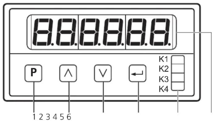
| 1 | Programming button: changeover to the programming mode |
| 2 | Setting buttons up/down: selection of the parameter address and the parameter valueSetting: incremental by pressing briefly or scrolling by holding pressedQuick run: holding the setting button and the programming button pressed at the same time |
| 3 | |
| 4 | Input button: acknowledgement of the parameter address and the parameter value |
| 5 | LED displays:K1 is lit: unit is ready for operationK2 is lit: output "min" is switched (set minimum value has been reached)K3 is lit: output "max" is switched (set maximum value has been reached)K4 is lit: output "display 0" is switched (display value 0 has been reached) |
| 6 | display (input values, parameter addresses and parameter values) |
3. Mounting
Mount the unit with two clamps in the control panel, cutout 91 x 43mm.
4. Electrical connection

Disconnect the installation before connecting the unit. The plug-in terminal strip features reverse polarity protection.
Connection:
| X1 | ||
| 1 | GND+24 V DC IN | DC supply |
| 2 | ||
| 3 | GND+5 V DC OUT | sensor supply |
| 4 | ||
| 5 | + 12 V DC OUT | |
| 6 | Input A | |
| 7 | Input B | signal inputs |
| 8 | Input C | |
| 9 | Input D | |
| 10 | GND —— 10 V+ /- —— | analog outputs(Only for the articleE89121,with all other unitstheseterminals mustnot be used). |
| 11 | ||
| 12 | + —— 20 mA | |
| 13 | - —— | |
| 14 | OUT 1 (min) | |
| 15 | OUT 2 (max) | outputs |
| 16 | OUT 3 (display 0) | |
| 17 | + 24 V Com | |
| X2 | ||
| L 230 V AC | AC supply | |
| L 115 V AC | ||
| N | ||
Voltage supply
- either AC on terminals L/N
• or DC on terminals 1 and 2.
Sensor supply
- either internally by DY340 (5V on terminals 3 and 4, 12 V on terminals 3 and 5)
- or externally. With an external sensor supply, L- of the external source must be connected with terminal 3 of the DY340.
In the case of DC operation of the DY340 the sensor can be directly supplied by the supply voltage (external).
The terminals 1 to 17 are electrically isolated from the mains.
Connection of sensors:
| 3-wire DC | 2-wire DC / NAMUR pulse pick-up | encoder |
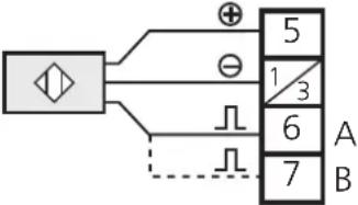 | 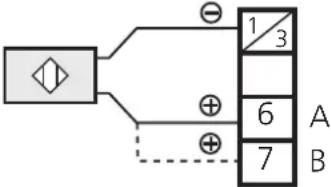 | 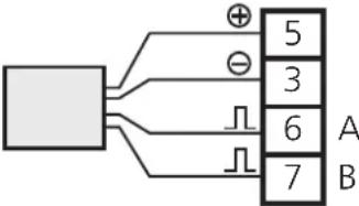 |
If NAMUR pulse pick-ups are used in Ex areas, a suitable separating amplifier must be connected between the NAMUR pulse pick-up and DY 340.
To guarantee safe functioning, signal cables and load cables should be laid separately. Use screened cable if necessary.
- Programming
| 1 | Changeover to the programming mode | Press the Button for a short time. ➔ P00 is shown in the display. |
| 2 | Selection of the parameter to be changed | Press the Or button until the requested parameter is shown in the display.* |
| Press the Button. The current parameter value is shown in the display. | ||
| 3 | Setting of the parameter value | Press the Or button until the requested parameter value is shown in the display. * |
| Press the Button. The next parameter is shown in the display. Continue with step 2. | ||
| If no button is pressed any more, the unit will return to the operating mode after 10s. The changed parameter values will become active.** | ||
*Setting: incremental by pressing briefly or scrolling by holding pressed.
Quick run: holding the or and buttons pressed.
**Active termination of the programming mode: Select parameter P85, enter value 1 and acknowledge with the button.
Locking/unlocking
The unit can be locked to prevent unwanted adjustment of the set parameters.
Select parameter P00, enter value 1 and acknowledge with the button.
For unlocking:
- Press the Button for a short time. will be shown in the display.
-
Now press the ☐ and buttons one after the other within 5s.
-
Adjustable parameters
| Parameter Parameter value | ||
| P00 | keyboard locking | 0 = keyboard locking inactive1 = keyboard locking active |
| P01 | operating mode 1 ... 23 (see from page 23) | |
| P02 | operand:numerical value to calculate the display value | range of values: 1 ... 50 000(see from page 23) |
| P03 | input level for all inputs | 1 = HTL (LOW= 0 ... 5 V HIGH = 8 ... 30 V)2 = TTL (LOW= 0 ... 1 V HIGH = 2.5 ... 6 V) |
| P04 | input characteristics for all inputs | 1 = NPN2 = PNP |
| P05 | frequency division for input A | 1 = 1:12 = 1:103 = 1:1004 = 1:10005 = 1:10000 |
| P06 | frequency division for input B | |
| P07 | decimal point of the display | range of values: 0 ... 50 = none, 5 = 5 decimal places |
| P08 | start/stop characteristics for time measurement | 1 ... 5 (see page 28) |
| P09 | reset characteristics for time measurement 1 . | . 4 (see page 29) |
| P10 | preset 1 (minimum value):display value at which OUT 1 (min.)is to switch | range of values: 0 ... 999 999 |
| P11 | preset 2 (maximum value):display value at which OUT 1 (max.)is to switch | range of values: 0 ... 999 999 |
| P12 | switching characteristics of the outputsOUT 1 (min.) and OUT 2 (max.) | 1 = both outputs switch when the relevant preset value has been exceeded2 = output (min.) switches when the current value is below the preset value, output (max.) switches when the current value is above the relevant preset value |
| P15 | last value memory for time measurement | 1 = ON / 2 = OFF |
| P18 | fleeting time for OUT 1 (min.)The output changes its switching statuswhen the current value is above or belowthe limit value for the length of the setfleeting time.Then it returns to the initial status. | range of values: 0.00 ... 9.99s(0.00 = fleeting time not active, output is switched statically) |
| P19 | fleeting time for OUT 2 (max.) | |
| P20 | fleeting time for OUT 3 (display 0) | |
| P21 | function assignment for input C | 0 = no function5 = delete min./max. memory6 = keyboard locking7 = counting interruption8 = reset |
| P22 | function assignment for input D | |
| P23 | function assignment for the button | 0 = no function5 = delete min./max. memory7 = counting interruption8 = reset |
| P24 | function assignment for the button | |
| P25 | function assignment for the button | |
| P26 | read min. value memory display of the current | minimum value |
| P27 | read max. value memory display of the current | maximum value |
| P28 | direction-dependent display /direction signal by OUT 3 | 1 = without sign, without direction signal2 = with sign and direction signal OUT 3(see page 23) |
| P29 | start-up delay for OUT 1 (min.)The output switches after the start-up delay has elapsed.The time starts with the application of the operating voltage or after reset. | range of values:0s = start-up delay not active0.01 ... 99.98s start-up delay active99.99s = output "min." remains locked until the current value falls below the preset min. value for the first time |
| P30 | mean-value generationdisplay value = measured value of the current measuring cycle or mean value of a number of preceding measuring cycles1 measuring cycle = 200ms | 1 = no mean-value generationdisplay value = value of the current measuring cycle2 ... 16 = mean-value generation across the last2 ... 16 measuring cycles |
| P31 | reset timereset of the display when the current value falls below a minimum input frequency or a maximum time interval between 2 input pulses is exceeded | 0 ... 99.99s |
| P74 | delete min./max. memory | 0 = do not delete memory1 = delete memory |
| Settings for analog outputs (only for the article E89121) | ||
| P33 | final analog valuedisplay value at which the analog output supplies the maximum output signal | range of values: 0 ... 999 999 |
| P34 | type of the analog signal | 1 = 0 ... ±10 V (max. 5 mA)2 = 0 ... 20 mA (max. load: 300 Ω)3 = 4 ... 20 mA (max. load: 300 Ω) |
| P35 | adaptation of the analog zero valuedisplay value at which the analog output supplies the minimum output signal ("0") | range of values: -2000 ... +2000 |
| P36 | maximum output level of the analog output | 1000 = 10.0 V / 20.0 mA600 = 6.0 V / 12.0 mA150 = 1.5 V / 3.0 mA |
7. Basic settings
7. 1. Input configuration
These two parameters must always be set:
-
Set the unit to the level of the pulse pick-ups with the parameter P03 (P03 = 1: HTL / P03 = 2: TTL).
-
Set the unit to the electrical design of the pulse pick-ups with the parameter P04 (P04 = 1: npn switching / P04 = 2: pnp switching).
These two settings apply to all 4 inputs.
Configuration with the connection of NAMUR pulse pick-ups: P03 = 1 and P04 = 1.
The level of the input signal depends on the setting with P04:
- signal = HIGH if P04 = 2 (pnp switching),
- signal = LOW if P04 = 1 (npn switching).
The following parameters can be set as needed:
- Frequency division: reduction of the input frequency in 5 defined division ratios (parameter P05 for input A, parameter P06 for input B).
- Function assignment for the inputs C and D: A signal to the input executes one of the following functions: reset, counting interruption, reset min/max, keyboard locking (parameter 21 for input C, parameter P22 for input D).
7.2. Configuration of the display
- Decimal point in the display: 0 to 5 decimal places (parameter P07).
- Mean-value generation: the display shows the mean value of a defined number of measuring cycles (not the value of the current measuring cycle); (parameter P30).
7. 3. Configuration of the transistor outputs
- Preset 1: limit value at which OUT 1 changes its switching characteristics (parameter P10).
- Preset 2: limit value at which OUT 2 changes its switching characteristics (parameter P11).
- Switching function of OUT 1 and OUT 2: switch when the current value is above / below the preset value (parameter P12).
- Fleeting time for OUT 1 ... OUT 3 (parameters P18 ... P20).
- Start-up delay: Suitable for monitoring the min. value (OUT 1). The error signal "below min. value", for instance, can be suppressed until the plant section has been run up (parameter P29).
7. 4. Configuration of the analog output (article no. E89121)
The analog output operates in proportion to the display. It considers mean-value generation and adapts the polarity to the sign.
-
Set the type of the analog signal with the parameter P34.
-
Set the maximum output level with the parameter P36.
-
Set the display value at which the analog output is to supply the maximum output signal with the parameter P33.
-
If needed, set the zero point of the analog signal with the parameter P35 (default value is "0").
7.5. Additional functions
- Min./max. memory: The unit permanently stores the smallest measured value and the highest measured value.
The values can be displayed (parameters P26 and P27). They can also be deleted:
- Set value "1" for parameter P74
- or assign this function to one of the front buttons (parameter P23, P24 or P25) and delete the memory during operation by pressing a button.
- Counting interruption / reset
Assign this function (parameter P23, P24 or P25) to one of the front buttons or configure input C or input D (with the parameter P21 or P22) and carry out a counting interruption and/or reset by means of an external signal.
- Keyboard locking: You can lock the keyboard by means of an external signal to input C or input D (see the parameter P21 or P22).
8. Application-specific settings
8. 1. Detection of high rotational speeds
With this operating mode pulses per time unit are counted (measuring principle pulse counting). It is suitable for applications with high input frequencies.
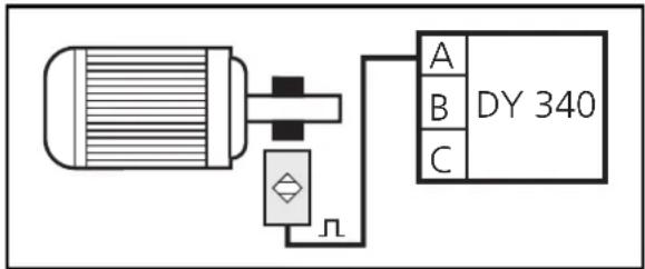
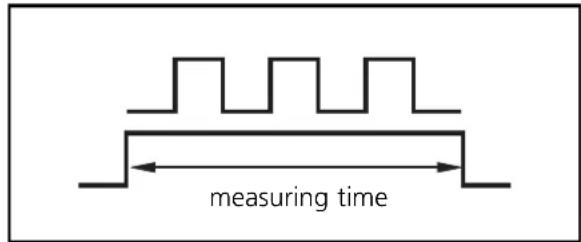
- Set the parameter P01 to the value 1.
- Calculate the operand (O) with 3 decimal places:
$$ \boxed { \begin{array}{c} O = D \mid f _ {1} \end{array} } $$
O = operand
D = desired display value
(What value is to be displayed, how many pulses, pieces, metres per time unit? The unit of measurement must be selected in such way that whole-number values result, e. g. 65.3 → 653). f_l = input frequency in Hz
- Set the parameter P02 to this value (enter the numerical value without decimal place).
- If needed, set the position of the decimal point with the parameter P07 (with P07 = 1 for example the value 653 is displayed as "65.3").
Example:
In the case of an input frequency of 800 Hz the value 1200 is to be displayed:
- D = 1200
- f_1 = 800 Hz
$$ \boxed {O = 1 2 0 0 \mid 8 0 0 = 1. 5 0 0 s} $$
Set the parameter P02 to the value 1500, P07 to the value 0 (no decimal place), parameter P28 to the value 1 (without sign).
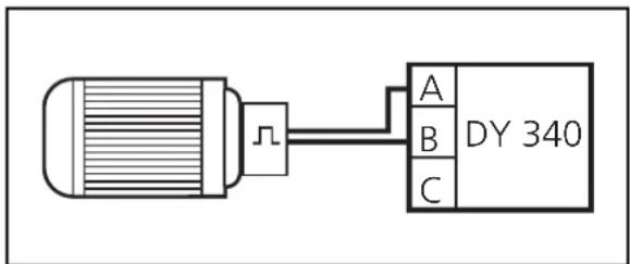
Direction-dependent display with changing sign
flowchart
graph LR
    A["Device"] --> B["DY 340"]
    B --> C["A"]
    B --> D["B"]
    B --> E["C"]
- Connect the pulses of a 2-channel encoder to the inputs A and B.
- Set the parameter P28 to the value 2.
The display is as follows:
| pulse sequence display OUT 3 LED K4 | ||
| A before B without sign not switched (OFF) OFF | ||
| B before A with sign "-" switched (ON) ON |
8. 2. Detection of rotational speeds, cycles, number of pieces
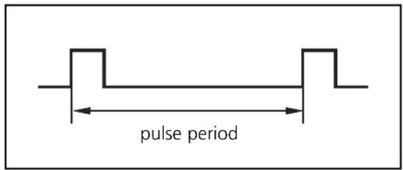
With this operating mode the pulse sequence is evaluated (measuring principle pulse period). It is suitable for applications with low input frequencies. One single pulse brings about a measuring result.
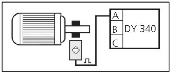
- Set the parameter P01 to the value 2.
- If needed: Determine a suitable frequency division with the parameter P05 (reduction of the input frequency). After the frequency divider the value for f_i should be max. 30 Hz.
(If the pulse pick-up is connected to input B, set the frequency division with the parameter P06).
- Calculate the operand (O):
$$ \boxed { \begin{array}{c} O = D \mid f _ {1} \end{array} } $$
O = operand
D = desired display value
(What value is to be displayed, how many pulses, pieces, metres per time unit? The unit of measurement must be selected in such way that whole-number values result, e. g. 65.3 → 653).
f_1 = input frequency in Hz
- Set the parameter P02 to the calculated value (only enter the places before the decimal point).
- If needed, set the position of the decimal point with the parameter P07 (example: with P07 = 1 the value 653 is displayed as "65.3").
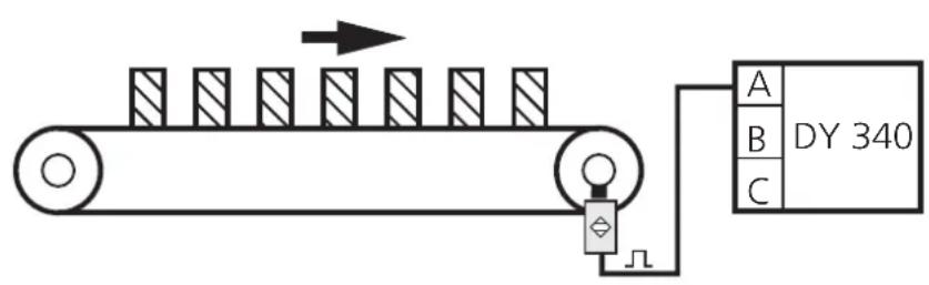
Example 1: display of the belt speed in m/s
If the driving roller turns at 184 rpm, the belt moves at 65.3 m/s. The roller is detected by 4 cams.
- for 184 rpm "65.3" is to be displayed, therefore: D = 653 (whole-number value)
- f_1 = 184 [rpm] x 4 = 736 [pulses/min] = 12.266 Hz
$$ 0 = 6 5 3 \mid 1 2. 3 = 5 3. 0 8 $$
After setting the operand to 53 and the decimal point the unit displays the rotational speed in m/s.
Example 2: display of the rotational speed in rpm
The drive turns between 0.3 and 10 Hz (18 to 600 rpm) and is detected by means of 8 cams.
- D = 60 [rpm] (for 60 rpm "60" is to be displayed),
- f_1 = 60 [rpm] x 8 = 480 [pulses/min] = 8 Hz
$$ 0 = 6 0 \mid 8 = 7. 5 (\text { rounded to } 7 \text { or } 8) $$
After setting the operand 7 (or 8) the unit displays the rotational speed in rpm.
The display is more accurate with a frequency division of 1 : 10 (P05 = 2):
$$ O = 6 0 \mid 0. 8 = 7 5 $$
Or when you proceed as follows:
- Increase the value to be displayed by the factor 10 and
- set the decimal point to display the value with one decimal place.
$$ 0 = 6 0 0 \mid 8 = 7 5 $$
After setting the operand to 75 and the decimal point the unit displays the rotational speed in rpm.
Reset time
In the operating mode P02 = 2 the duration of a pulse is measured and the value to be displayed is calculated. The display only changes with the arrival of the following pulse (irrespective of the length of the time interval between the pulses).
You can determine that the display is reset to 0
- when the current value falls below a minimum input frequency (f_min)
- or when a maximum time interval between 2 pulses is exceeded.
- Calculate the time value from the input frequency (reset time t [s] = 1/ f _min [Hz]) and set the parameter P31 to this value (input format: x.xx seconds);
- or directly set the parameter P31 to the maximum time value (input format: x.xx seconds).
8. 3. Detection of throughput times (reciprocal display)
flowchart
graph LR
    A["Input A"] --> B["Process Box"]
    B --> C["Output C"]
    style A fill:#f9f,stroke:#333
    style B fill:#ccf,stroke:#333
    style C fill:#cfc,stroke:#333
- Set the parameter P01 to the value 3.
- If needed: Set a suitable frequency division with the parameter P05 (reduction of the input frequency). The value for f1 should be max. 30 Hz. (If the pulse pick-up is connected to input B, set the frequency division with the parameter P06).
- Calculate the operand (O):
$$ O = D \cdot f _ {1} $$
O = operand
D = desired display value
f_1 = input frequency in Hz
-
Set the parameter P02 to this value (enter the places before the decimal point).
-
If needed, set the decimal point with the parameter 07.
Example:
The belt passes through a furnace which is 10 m long in 10 minutes (600 s). With a belt speed of 1 m/min the drive turns at 300 rpm (this corresponds to 5 Hz), it is detected with 1 cam.
- D = 600 [s]
- f_1 = 5
$$ O = 6 0 0 \cdot 5 = 3 0 0 0 $$
After setting the operand to 3000 the unit displays the current throughput time in seconds.
Display format:
By selecting the time basis and setting the parameter P01 four different display formats can be defined:
| display format time basis value for parameter P01 | ||
| 999999 (s) 1s 3 | ||
| 99.59.59 (h:min:s) | 1s | 4 |
| 99.59.99 (min:s:1/100s) | 0.01s 5 | |
| 9999.59 (s) | 0.01s 6 | |
8. 4. Detection of speed by measuring the time interval
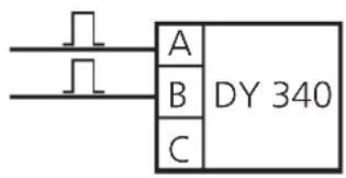
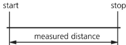
The speed is calculated from the time interval between the "start" pulse and the "stop" pulse.
stop pulse start pulse
- Select the time basis which corresponds to the approx. time interval from the following table. Set the parameter P01 to the corresponding value.
| time base value for parameter P01 | |
| 0.01s 7 | |
| 0.10s 8 | |
| 1.00s 9 | |
| 10.00s 10 | |
- Calculate the operand to determine the display.
$$ O = s \mid t $$
d = measured distance in m, km (depending on the requested display); t = selected elapsed time in s, min, h (depending on the requested display).
-
Set the parameter P02 to this value (enter the numerical value without decimal place).
-
If needed, set the decimal point with the parameter 07.
Examples:
| measured distance (s) time | base (t) operand (O) | |
| 10m 1s | 10 | 1 = 10(display in m/s) | |
| 0.5m 0.01s | 0.5 | 0.01 = 50(display in m/s) | |
| 50 · 3600 | 1000 = 180(display in km/h) |
8. 5. Industrial timer
The time between the "start" pulse and "stop" pulse is measured and indicated.
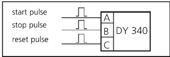
flowchart
graph LR
    A["Start Pulse"] --> B["Stop Pulse"]
    B --> C["Reset Pulse"]
    D["DY 340"] --> E["A"]
    D --> F["B"]
    D --> G["C"]
- Select the resolution and display format from the following table and set the parameter P01 to the corresponding value.
| resolution format value for parameter P01 | ||
| 1ms | 999.999 (s) | 11 |
| 10ms | 9999.99 (s) | 12 |
| 100ms | 99999.9 (s) | 13 |
| 1s 999999 (s) | 11 | |
| 0.001min | 999.999 (min) | 15 |
| 0.01min | 9999.99 (min) | 16 |
| 0.1min | 99999.9 (min) | 17 |
| 1min 999999 (min) | 18 | |
| 0.01h | 9999.99 (h) | 19 |
| 1s | 99.59.59 (h:min:s) | 20 |
| 0.01s | 99.59.99 (min:s:1/100s) | 21 |
| 1s | 9999.59 (s) | 22 |
| 1min | 9999.59 (min) | 23 |
- Select the start/stop setting from the following table and set the parameter P08 to the corresponding value.
| value for P08 | ||
| Counts time while input A is low. | INPUT A  START STOP START STOP | 0 |
| Counts time while input A is high. | INPUT A  START STOP START STOP | 1 |
| Counts time between the falling edge of A and the falling edge of B. | INPUT A  START :INPUT B START :INPUT B  | 2 |
| Starts and stops alternately with each falling edge of A. | INPUT A  START STOP START STOP START STOP START STOP | 3 |
| Counts time between two falling edges of A. | INPUT A  PERIOD TIME PERIOD TIME | 4 |
- Select the display and reset mode from the following table and set the parameter P09 to the corresponding value.
| display mode reset mode | value for P09 | |
| Real(current counting is displayed). | External | 0 |
| Memory(only the end result is displayed, it remains displayed until the next end result or reset pulse). | External | 1 |
| Real(current counting is displayed). | AUTO(with each start signal the counter starts at 0). | 2 |
| Memory(only the end result is displayed, it remains displayed until the next end result or reset pulse). | AUTO(with each start signal the counter starts at 0). | 3 |
9. Operation
After mounting, wiring and programming check the safe functioning of the unit. In case of correct use no maintenance measures are necessary.
10. Technical data
| Nominal voltage AC [V] | 115 / 230 |
| Nominal voltage DC [V] | 24 |
| Power consumption [VA] | 4 |
| Current consumption [mA] | 200 |
| Protection housing front | IP 44 |
| Operating temperature [°C] | 0 ... +45 |
| Dimensions [mm] | 96 x 48 x 150 |
| Control panel cutout [mm] | 91 x 43 |
| Inputs | 4 x npn, pnp, NAMUR; HTL or TTL |
| Input frequency [Hz] | 0.03 ... 25000 |
| Auxiliary voltage [V] | 24V, 60mA / 5V, 150mA / 12V, 150mA |
| Switching outputs | 3 x pnp, 5 ... 30V DC, 50mAshort circuit protected |
| Analog outputs (optional) | 0/4 ... 20 mA; 0 ... 10 V |
| Accuracy | ± 1 digit |
ifm Niederlassungen • Sales offices • Agences
- Function and features
- The unit
- Operating and indicating elements
- Mounting
- Electrical connection
- Voltage supply
- Sensor supply
- Locking/unlocking
- Basic settings
- 1. Input configuration
- Configuration of the display
- 3. Configuration of the transistor outputs
- 4. Configuration of the analog output (article no. E89121)
- Additional functions
- Application-specific settings
- 1. Detection of high rotational speeds
- Direction-dependent display with changing sign
- 2. Detection of rotational speeds, cycles, number of pieces
- Example 1: display of the belt speed in m/s
- Example 2: display of the rotational speed in rpm
- Reset time
- 3. Detection of throughput times (reciprocal display)
- Example:
- 4. Detection of speed by measuring the time interval
- 5. Industrial timer
- Operation
- Technical data
- ifm Niederlassungen • Sales offices • Agences
Brand : IFM
Model : Ecomat 200 DY340
Category : Monitor