
Ecomat 200 DA340 - Monitor IFM - Free user manual and instructions
Find the device manual for free Ecomat 200 DA340 IFM in PDF.
| Product type | Digital display (monitor) |
| Brand | IFM |
| Model | Ecomat 200 DA340 |
| Dimensions (W × H × D) | 96 × 48 × 150 mm |
| Panel cut-out | 91 × 43 mm |
| Weight | Approx. 200 g |
| Power supply | 115/230 V AC or 24 V DC |
| Power consumption | 200 mA / 4 VA |
| Enclosure protection (front) | IP44 |
| Ambient temperature | 0 °C to +45 °C |
| Analog inputs | 1 V / 10 V / x V (max 120 V) / 20 mA |
| Switching outputs | 3 × PNP, 5-30 V DC, 50 mA |
| Measurement time | 200 ms |
| Accuracy | ±0.05 % ±1 digit |
| Display | Digital LED |
| Main functions | Programming, linearization, offset, min/max memory, pulse duration, start-up delay |
| Maintenance | No maintenance required under normal use |
| Cleaning | Use a dry cloth; do not use solvents |
| Safety | Terminal block protected against polarity reversal; disconnect power before connecting |
| Spare parts | External resistors available for voltage range adaptation |
| Repairability | Repair by qualified technician only |
Frequently Asked Questions - Ecomat 200 DA340 IFM
User questions about Ecomat 200 DA340 IFM
0 question about this device. Answer the ones you know or ask your own.
Ask a new question about this device
Download the instructions for your Monitor in PDF format for free! Find your manual Ecomat 200 DA340 - IFM and take your electronic device back in hand. On this page are published all the documents necessary for the use of your device. Ecomat 200 DA340 by IFM.
USER MANUAL Ecomat 200 DA340 IFM
- Functions and features 11
- Operating and indicating elements 11
- Mounting page 12
- Electrical connection . page 12 Connection of sensors . page 13
- Programming 13
- Adjustable parameters 14
- Configuration of the display . page 15
- Configuration of the outputs . page 16
- Additional functions 17
- Operation 17
- Technical data page 17
1. Functions and features
The digital display is a universal unit for displaying and monitoring analog signals. The unit:
- picks up the signals of analog sensors
- processes them into a displayed value according to the parameters set
and indicates the current displayed value in the display. -
In addition the unit switches transistor outputs
-
OUT 1: switches when the preset minimum value has been exceeded or not been reached
- OUT 2: switches when the preset maximum value has been exceeded
- OUT 3: switches when the display value 0 has been reached.
The setting of the various parameters ensures that the function of the unit is variable within a great range of values and can thus be adapted to the individual application:
- configuration of the inputs and the display
(operating mode, scaling, decimal point, offset, linearisation, mean-value generation),
- configuration of the outputs
(preset, switching function, fleeting,start-up delay).
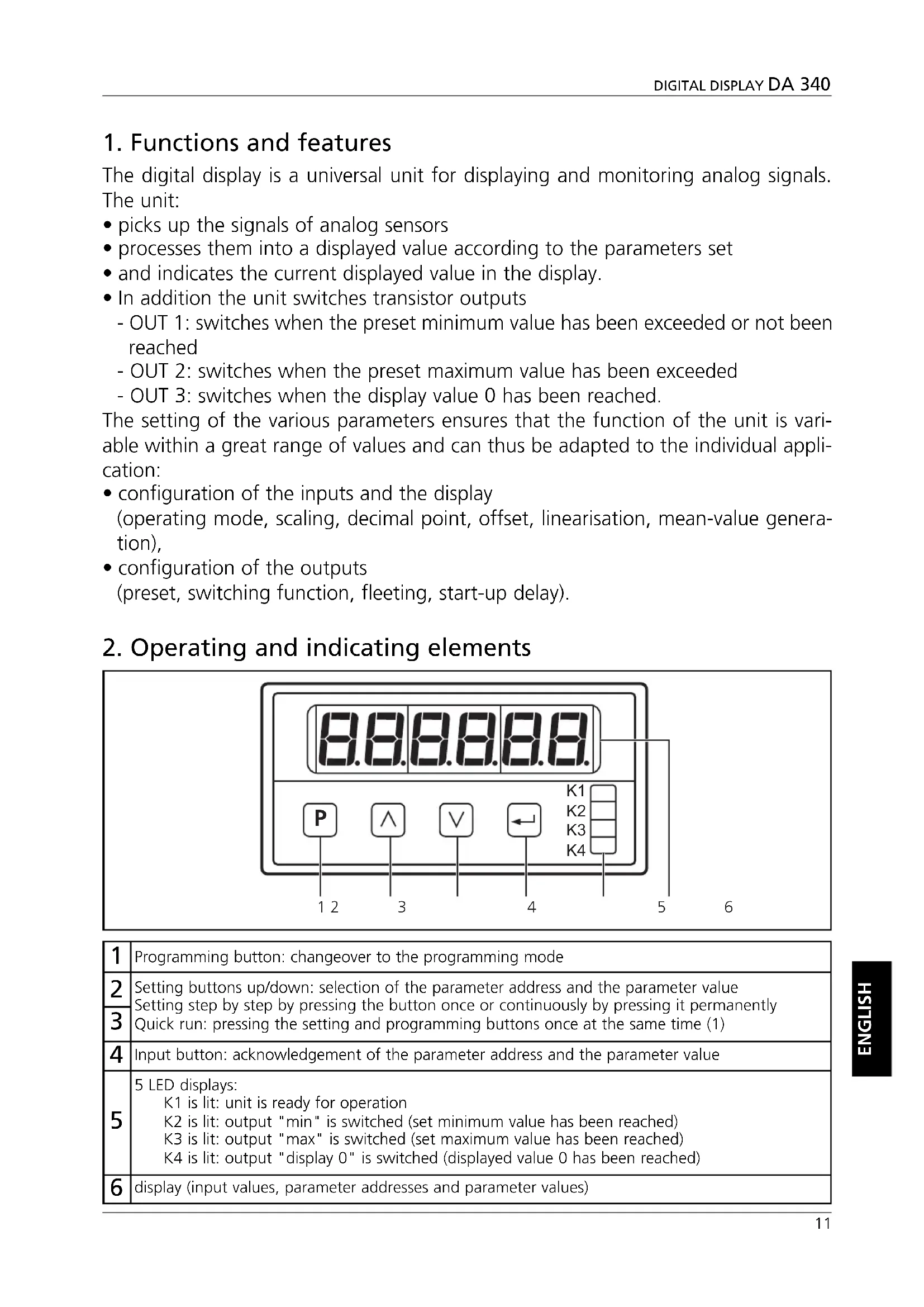
2. Operating and indicating elements
| 1 | Programming button: changeover to the programming mode |
| 2 | Setting buttons up/down: selection of the parameter address and the parameter value Setting step by step by pressing the button once or continuously by pressing it permanently Quick run: pressing the setting and programming buttons once at the same time (1) |
| 3 | |
| 4 | Input button: acknowledgement of the parameter address and the parameter value |
| 5 | 5 LED displays: K1 is lit: unit is ready for operation K2 is lit: output "min" is switched (set minimum value has been reached) K3 is lit: output "max" is switched (set maximum value has been reached) K4 is lit: output "display 0" is switched (displayed value 0 has been reached) |
| 6 | display (input values, parameter addresses and parameter values) |
3. Mounting
Mount the unit with two clamps in the control panel, cutout 91 × 43mm .
4. Electrical connection

Disconnect the installation. The plug-in terminal strip features reverse polarity protection.
Connection:
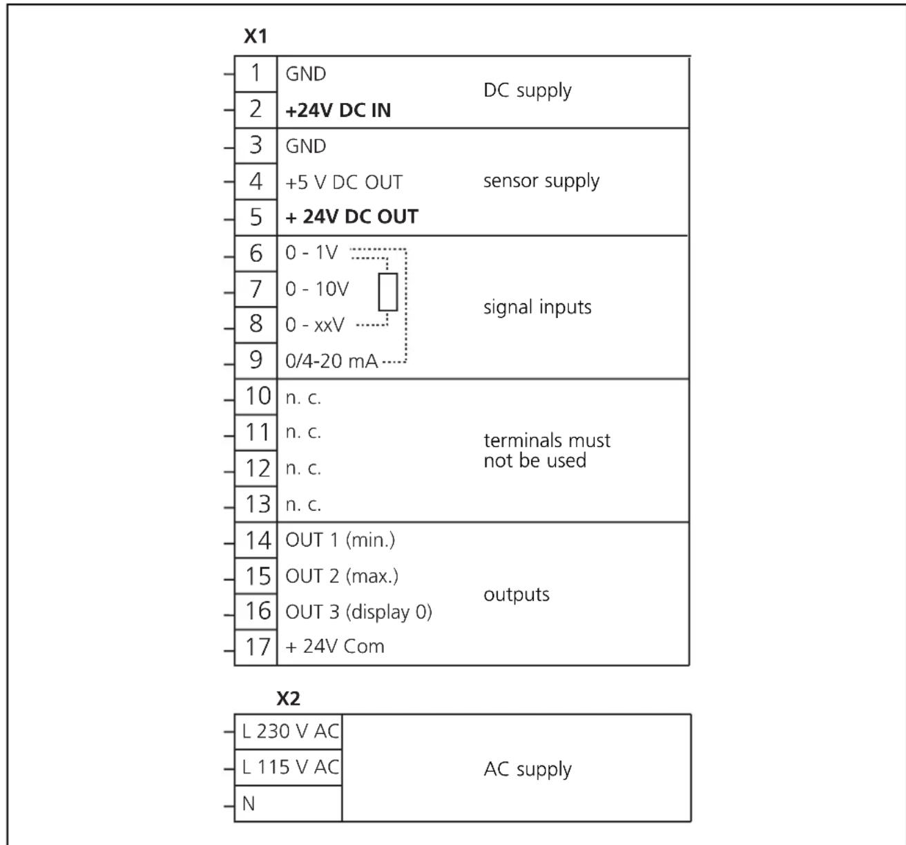
The terminals 1 to 17 are electrically isolated from the mains.
Connection of sensors (24 V DC):
| range 0 - 1 V range | 0 - 10 V range 0/4 - 20 | mA range 4 - 20 mA | |
| 3 5 6 | 3 5 7 | 3 5 6 9 | 4-20mA 5 6 9 |
| freely definable voltage range 0 - xx V |
| The maximum value of the voltage range can be assigned by an external resistor between terminals 8 and 6. |
| Calculation of the resistance value: R [kΩ] = (U [V] x 25) - 25 Umax = 120 V! |
To guarantee safe functioning, signal cables and load cables should be laid separately. Use screened cable if necessary.
5. Programming
| 1 | Changeover to the programming mode | Press the Button for a short time. P00 is shown in the display. |
| 2 | Selection of the parameter to be changed | Press the button until the requested parameter is shown in the display.* |
| Press the button. The current parameter value is shown in the display. | ||
| 3 | Setting of parameter | Press the button until the requested parameter value is shown in the display. * |
| Press the button. The next parameter is shown in the display. Continue with step 2. | ||
| If no button is pressed any more, the unit will return to the operating mode after 8s. The changed parameter values will become active.** | ||
Setting step by step by pressing the button once or continuously by pressing it permanently. Quick run: pressing the and buttons once at the same time.
*Active termination of the programming mode: Select parameter P85, enter value 1 and acknowledge with the button.
Locking/unlocking
The unit can be locked to prevent unwanted adjustment of the set parameters. Select parameter P00, enter value 1 and acknowledge with the button.
For unlocking:
- Press the button for a short time. will be shown in the display.
-
Now press the l and buttons one after the other within 5s.
-
Adjustable parameters
| Parameter Parameter value | ||
| P00 | keyboard locking | 0 = keyboard locking inactive1 = keyboard locking active |
| P01 | operating mode:- level of the input signal anddisplay mode proportional reciprocal | 1 = 0 ... 1 V; 0 ... xx V / proportional display2 = 0 ... 10 V / proportional display3 = 0 ... 20 mA / proportional display4 = 4 ... 20 mA / proportional display5 = 0 ... 1 V; 0 ... xx V / reciprocal display6 = 0 ... 10 V / reciprocal display7 = 0 ... 20 mA / reciprocal display8 = 4 ... 20 mA / reciprocal display |
| P02 | scaling factor: numerical value to be displayed with themaximum of the input signal | range of values: 1 ... 999 999 |
| P07 | decimal point of the display | range of values: 0 ... 50 = none, 5 = 5 places after the point |
| P10 | preset 1 (minimum value):displayed value at which OUT 1 (min.)is to switch | range of values: 0 ... 999 999 |
| P11 | preset 2 (max.):displayed value at which OUT 2 (max.)is to switch | range of values: 0 ... 999 999 |
| P12 | switching performance of the outputsOUT 1 (min.) and OUT 2 (max.) | 1 = both outputs switch when the relevant presetvalue has been exceeded2 = output (min.) switches when the relevant preset value has not been reached, output(max.) switches when the relevant preset value has been exceeded |
| P17 | offset numerical value which is added to thecurrent displayed value | range of values: -99999 ... +99999 |
| P16 | linearisationfree definition of a linearisation graph forthe displayed values | 0 = linearisation inactive1 = linearisation active |
| P18 | fleeting time for OUT 1 (min.)The output changes its switching status whenthe limit value has been exceeded or has notbeen reached for the length of the set fleet-ing time. Then it returns to the initial status. | range of values: 0.00 ... 9.99s(0.00 = fleeting time not active, output is switchedstatically) |
| P19 | fleeting time for OUT 2 (max.) range of values | 0.00 ... 9.99s; (0,00: see P18) |
| P20 | fleeting time for OUT 3 (display 0) | range of values: 0.00 ... 9.99s; (0.00: see P18) |
| P23 | function of the key in the operatingmode | 0 = no function5 = delete min./max. memory |
| P24 | function of the key in the operatingmode | 0 = no function5 = delete min./max. memory |
| P25 | function of the key in the operatingmode | 0 = no function5 = delete min./max. memory |
| P26 | read min./max. memory display of the current | minimum value |
| P27 | read max./min. memory display of the current | maximum value |
| P29 | start-up delay for OUT 1 (min.)The output switches after the start-up delayhas elapsed.The time starts with the applica-tion of the operating voltage or after reset. | range of values:0s = start-up delay not active0.01 ... 99.98s start-up delay active99.99s = output "min." remains locked until thedisplayed value falls below the preset min. valuefor the first time |
| P30 | mean-value generation displayed value = measured value of the current measuring cycle or mean value of a number of preceding measuring cycles 1 measuring cycle = 200ms | 1 = no mean-value generation displayed value = value of the current measuring cycle 2 ... 16 = mean-value generation across the last 2 ... 16 measuring cycles |
| P41 | x values of linearisation (see P16) | range of values: -999 999 ... +999 999 (for each of the 10 parameters) |
| P50 | y values of linearisation (see P16) | range of values: -999 999 ... +999 999 (for each of the 10 parameters) |
| P60 | delete min./max. memory | 0 = do not delete memory 1 = delete memory |
Parameters not listed do not have any function.
7. Configuration of the display
- Connect the sensor. Select the terminals which are intended for the voltage / current range of the sensor (see connection of sensors).
- Set the operating mode with parameter P01 (measuring range and evaluation characteristics).
- Set the value to be displayed at max. sensor signal with parameter P02. The unit then calculates the displayed value as follows:
| proportional display | reciprocal display |
| input signal max. value of the measuring range xscaling factor | max. value of the measuring range input signal xscaling factor |
This completes the configuration of the display. The unit is ready for operation.
If requested, the following additional functions can be set:
- Decimal point in the display: 0 to 5 places after the comma (parameter P07).
- Offset: basic value which is added to or subtracted from the displayed value (parameter P17).
- Mean-value generation: the display outputs the mean value of a defined number of measuring cycles (not the value of the current measuring cycle); (parameter P30).
- Linearisation: The unit internally calculates the graph of the displayed values from measured values and parameter settings. For special applications you can replace this graph by a freely defined linearisation graph (to compensate for measuring errors of sensors or for special applications). To do so replace 10 values of the graph calculated internally (x values) by 10 freely defined displayed values (y values). The unit links the points between the y values by straight lines and thus creates a freely defined graph of the displayed values. Proceed as follows:
a) Parameter setting of the display as described above (1 to 3).
b) Enter up to 10 × values (parameters P41 to P50). The first value (in P41) should be "0", the last value (in P50) the maximum value of the measuring range.
c) Enter the y values which are to replace the x values (parameters P51 to P60).
d) Then set parameter P16 to the value 1.
Example of linearisation:
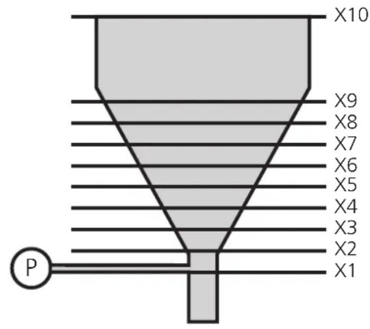
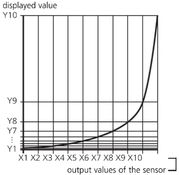
An analog pressure sensor (P) is to indicate the volume of the target material in a vessel.
The output signal of the sensor is proportional to the level of the tank, however not to the volume. Proceed as follows to receive a volume display:
- Divide the non-linear area of the tank into 8 parts of the same size.
- Enter the output values of the sensor for level X1 up to X9 (parameters P41 to P49). Enter the measured value for the full tank in parameter P50.
- Now enter the requested displayed value (target quantity) in parameters P51 to P60.
- Then set parameter P16 to the value 1.
8. Configuration of the outputs
Set the following parameters:
- Preset 1: limit value at which OUT 1 changes its switching performance: parameter P10.
- Preset 2: limit value at which OUT 2 changes its switching performance: parameter P11.
- Switching function of OUT 1 and OUT 2: switch when the preset has been exceeded / not reached: parameter P12.
- Fleeting time (pulse stretching) for OUT 1 ... OUT 3: parameters P18 ... P20.
- Start-up delay: Suitable for monitoring the min. value (OUT 1). The error signal "min. value not reached", for instance, can be suppressed until the plant has been run up: parameter P29.
9. Additional functions
- Min./max. memory: The unit permanently stores the smallest measured value and the highest measured value.
The values can be displayed (parameters P26 and P27). They can also be deleted:
- Set value "1" for parameter P74
- or assign this function to one of the front buttons (parameters P23, P24 or P25) and delete the memory during operation by pressing the button.
10. Operation
After mounting, wiring and programming check the safe functioning of the unit. In case of correct use no maintenance measures are necessary.
11. Technical data
| Nominal voltage AC [V] | 115 / 230 |
| Nominal voltage DC [V] | 24 |
| Power consumption [VA] | 4 |
| Current consumption [mA] | 200 |
| Protection housing front | IP 44 |
| Operating temperature [℃] | 0 ... +45 |
| Dimensions [mm] | 96 x 48 x 150 |
| Control panel cutout [mm] | 91 x 43 |
| Analog inputs | 1V / 10V / xV (max. 120V) / 20 mA |
| Auxiliary voltage [V] | 24V, 60mA / 5V, 150mA / 12V, 150mA |
| Outputs | 3 x pnp, 5 ... 30V DC, 50mA |
| Measuring time [ms] | 200 |
| Accuracy | ±0.05%; ± 1 digit |
Contenu
Raccordement des capteurs (24 V DC):
| plage 0 - 1 V plaque | 0 - 10 V plaque 0/4 - 20 | mA plaque 4 - 20 mA | |
| 3 5 6 | 3 5 7 | 3 5 6 9 | 4-20mA 5 6 9 |

- Functions and features
- Operating and indicating elements
- Mounting
- Electrical connection
- Connection:
- Connection of sensors (24 V DC):
- Programming
- Locking/unlocking
- Configuration of the display
- Example of linearisation:
- Configuration of the outputs
- Additional functions
- Operation
- Technical data
- Contenu
- Raccordement des capteurs (24 V DC):
Brand : IFM
Model : Ecomat 200 DA340
Category : Monitor