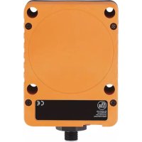
KD5039 - Capacitive proximity sensor IFM - Free user manual and instructions
Find the device manual for free KD5039 IFM in PDF.


User questions about KD5039 IFM
0 question about this device. Answer the ones you know or ask your own.
Ask a new question about this device
Download the instructions for your Capacitive proximity sensor in PDF format for free! Find your manual KD5039 - IFM and take your electronic device back in hand. On this page are published all the documents necessary for the use of your device. KD5039 by IFM.
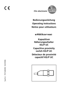
USER MANUAL KD5039 IFM
Operating instructions
Capacitive sensor
KB / KD /
KI
Contents
1 Preliminary note 3
1.1 Symbols used 3
2 Safety instructions.... 4
3 Intended use.... 5
4 Installation.... 6
4.1 Minimum distance for flush installation 6
4.2 Minimum distance for non-flush installation.... 6
4.3 Minimum distance when installing several units 6
4.4 Minimum distance when installing type KD 7
5 Electrical connection.... 8
5.1 Connection systems 8
5.1.1 2-wire technology 8
5.1.2 3-wire technology 8
5.2 Setting the output function for type KGE 8
5.3 Setting the output function for type KDE 8
5.3.1 2-wire technology 9
5.3.2 3-wire technology 9
6 Settings.... 10
6.1 Sensing range.... 10
6.2 Setting the output function via wire link for type KI with connector.... 10
6.3 Setting the output function via wire link for type KIE / KGE 10
7 Operation 11
8 Maintenance, repair and disposal 12
1 Preliminary note
You will find instructions, technical data, approvals, accessories and further information using the QR code on the unit / packaging or at www.ifm.com.
1.1 Symbols used
√ Requirement
Instructions
Reaction, result
[...] Designation of keys, buttons or indications
→ Cross-reference

Important note
Non-compliance may result in malfunction or interference.

Information
Supplementary note
2 Safety instructions
- The unit described is a subcomponent for integration into a system.
- The system architect is responsible for the safety of the system.
-
The system architect undertakes to perform a risk assessment and to create documentation in accordance with legal and normative requirements to be provided to the operator and user of the system. This documentation must contain all necessary information and safety instructions for the operator, the user and, if applicable, for any service personnel authorised by the architect of the system.
-
Read this document before setting up the product and keep it during the entire service life.
- The product must be suitable for the corresponding applications and environmental conditions without any restrictions.
- Only use the product for its intended purpose (→ Intended use).
- Only use the product for permissible media.
- If the operating instructions or the technical data are not adhered to, personal injury and/or damage to property may occur.
- The manufacturer assumes no liability or warranty for any consequences caused by tampering with the product or incorrect use by the operator.
- Installation, electrical connection, set-up, operation and maintenance of the product must be carried out by qualified personnel authorised by the machine operator.
- Protect units and cables against damage.
3 Intended use
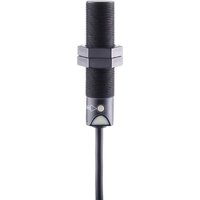
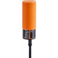
The unit detects without contact metals, almost all plastics, glass, ceramics, wood, paper, oils, greases, water and all hydrous materials and indicates their presence by a switching signal.
4 Installation
For flush installation of non-flush units the sensor properties change and the sensor may remain permanently switched (loss of function).
4.1 Minimum distance for flush installation
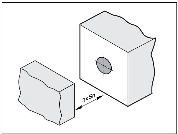
Sn: Sensing range
Fig. 1: Minimum distance for flush installation
4.2 Minimum distance for non-flush installation
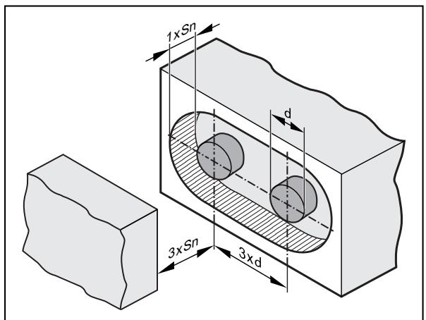
d: Diameter Sn: Sensing range
Fig. 2: Minimum distance for non-flush installation
4.3 Minimum distance when installing several units

d: Diameter Sn: Sensing range
Fig. 3: Minimum distance when installing several units
4.4 Minimum distance when installing type KD

Sn: Sensing range
Fig. 4: Minimum distance for non-flush installation of type KD

The distances need to be checked and determined by the users themselves according to their application.
5 Electrical connection
The unit must be connected by a qualified electrician.
The national and international regulations for the installation of electrical equipment must be adhered to.
▶ Disconnect power.
▶ Connect the unit as specified in the data sheet / type label.
Use a miniature fuse according to the technical data sheet, if specified. Recommendation: Check the safe functioning of the unit after a short circuit.
5.1 Connection systems
5.1.1 2-wire technology
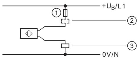
Fig. 5: 2-wire technology
1: Miniature fuse (for AC units)
2: Negative switching
3: Positive switching
5.1.2 3-wire technology
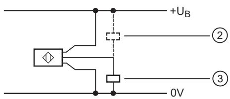
Fig. 6: 3-wire technology
2: Negative switching
3: Positive switching
5.2 Setting the output function for type KGE

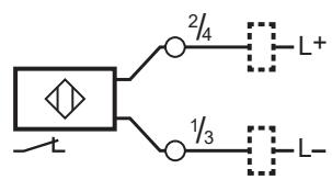
Fig. 7: Terminal chamber DC PNP/NPN
5.3 Setting the output function for type KDE
5.3.1 2-wire technology

Fig. 8: Terminal chamber AC/DC PNP/NPN
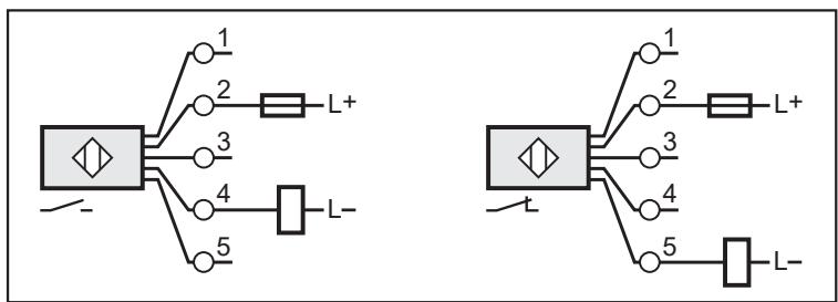
Fig. 9: Terminal chamber DC PNP/NPN
5.3.2 3-wire technology

Fig. 10: Terminal chamber DC NPN
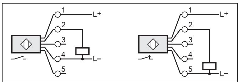
Fig. 11: Terminal chamber DC PNP

Fig. 12: Connector DC PNP
6 Settings
6.1 Sensing range
▶ Set the sensing range via the potentiometer using a screwdriver.

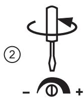
1 Increase the sensing range
2 Reduce the sensing range
6.2 Setting the output function via wire link for type KI with connector


1 NO (factory setting)
2 NC
Fig. 13: Setting the output function via the link in the connector
6.3 Setting the output function via wire link for type KIE / KGE


1: NO (wire link closed, factory setting)
2: NC (wire link open)
Fig. 14: Setting the output function via the wire link
▶ Use an appropriate tool to disconnect the wire link.
7 Operation
▶ Check whether the unit operates correctly.
▶ Bring about a unit response by taking suitable measures.
LED display
LED yellow out: switching output disabled
LED yellow ON: switching output enabled
8 Maintenance, repair and disposal
The operation of the unit is maintenance-free.
To ensure correct functioning, please note the following:
▶ Keep the sensing face and any clear spaces free from deposits and foreign bodies.
It is not possible to repair the unit.
After use dispose of the device in an environmentally friendly way in accordance with the applicable national regulations.

- 1 PRELIMINARY NOTE
- 1.1 SYMBOLS USED
- 2 SAFETY INSTRUCTIONS
- 3 INTENDED USE
- 4 INSTALLATION
- 4.1 MINIMUM DISTANCE FOR FLUSH INSTALLATION
- 4.2 MINIMUM DISTANCE FOR NON-FLUSH INSTALLATION
- 4.3 MINIMUM DISTANCE WHEN INSTALLING SEVERAL UNITS
- 4.4 MINIMUM DISTANCE WHEN INSTALLING TYPE KD
- 5 ELECTRICAL CONNECTION
- 5.1 CONNECTION SYSTEMS
- 5.1.1 2-WIRE TECHNOLOGY
- 5.1.2 3-WIRE TECHNOLOGY
- 5.2 SETTING THE OUTPUT FUNCTION FOR TYPE KGE
- 5.3 SETTING THE OUTPUT FUNCTION FOR TYPE KDE
- 5.3.1 2-WIRE TECHNOLOGY
- 5.3.2 3-WIRE TECHNOLOGY
- 6 SETTINGS
- 6.1 SENSING RANGE
- 6.2 SETTING THE OUTPUT FUNCTION VIA WIRE LINK FOR TYPE KI WITH CONNECTOR
- 6.3 SETTING THE OUTPUT FUNCTION VIA WIRE LINK FOR TYPE KIE / KGE
- 7 OPERATION
- 8 MAINTENANCE, REPAIR AND DISPOSAL
Brand : IFM
Model : KD5039
Category : Capacitive proximity sensor