DDO8900W - Doors LIFT-MASTER - Free user manual and instructions
Find the device manual for free DDO8900W LIFT-MASTER in PDF.
| Product Type | Dock door operator for sectional doors |
| Brand | LIFT-MASTER |
| Model | DDO8900W |
| Usage | Light commercial, non-residential |
| Power supply | 120 VAC, 60 Hz, 2.0 A |
| Rated load | 10 Nm |
| Maximum door weight | 136.1 kg (300 lb) |
| Maximum door width | 5.5 m (18 ft) |
| Lift height | Up to 4.3 m (14 ft) standard, up to 137.2 cm (54 in) high lift |
| Maximum door area | 16.7 m² (180 ft²) |
| Cycle speed | 10 complete cycles per hour max |
| Main safety | Protector System® (safety reversing sensors), mandatory cable tension monitor |
| Built-in functions | Integrated myQ® (Wi-Fi), optional backup battery (485LM), timer-to-close (TTC), manual emergency release |
| Bracket dimensions | For 2.5 cm (1 in) diameter torsion bar |
| Warranty | 2 years |
| Operating temperature | Not specified but indoor use for loading dock |
| Operator weight | Not specified, approximately 15-20 kg estimated |
| Compatible accessories | Automatic door lock 841LM, light curtain LC36A/LC36M, battery 485LM, LED lamp 827LM, Security+ 2.0 remote controls |
| Certifications | FCC Part 15, Industry Canada RSS |
Frequently Asked Questions - DDO8900W LIFT-MASTER
User questions about DDO8900W LIFT-MASTER
0 question about this device. Answer the ones you know or ask your own.
Ask a new question about this device
Download the instructions for your Doors in PDF format for free! Find your manual DDO8900W - LIFT-MASTER and take your electronic device back in hand. On this page are published all the documents necessary for the use of your device. DDO8900W by LIFT-MASTER.
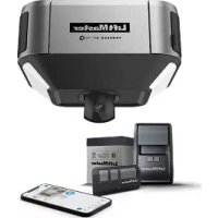
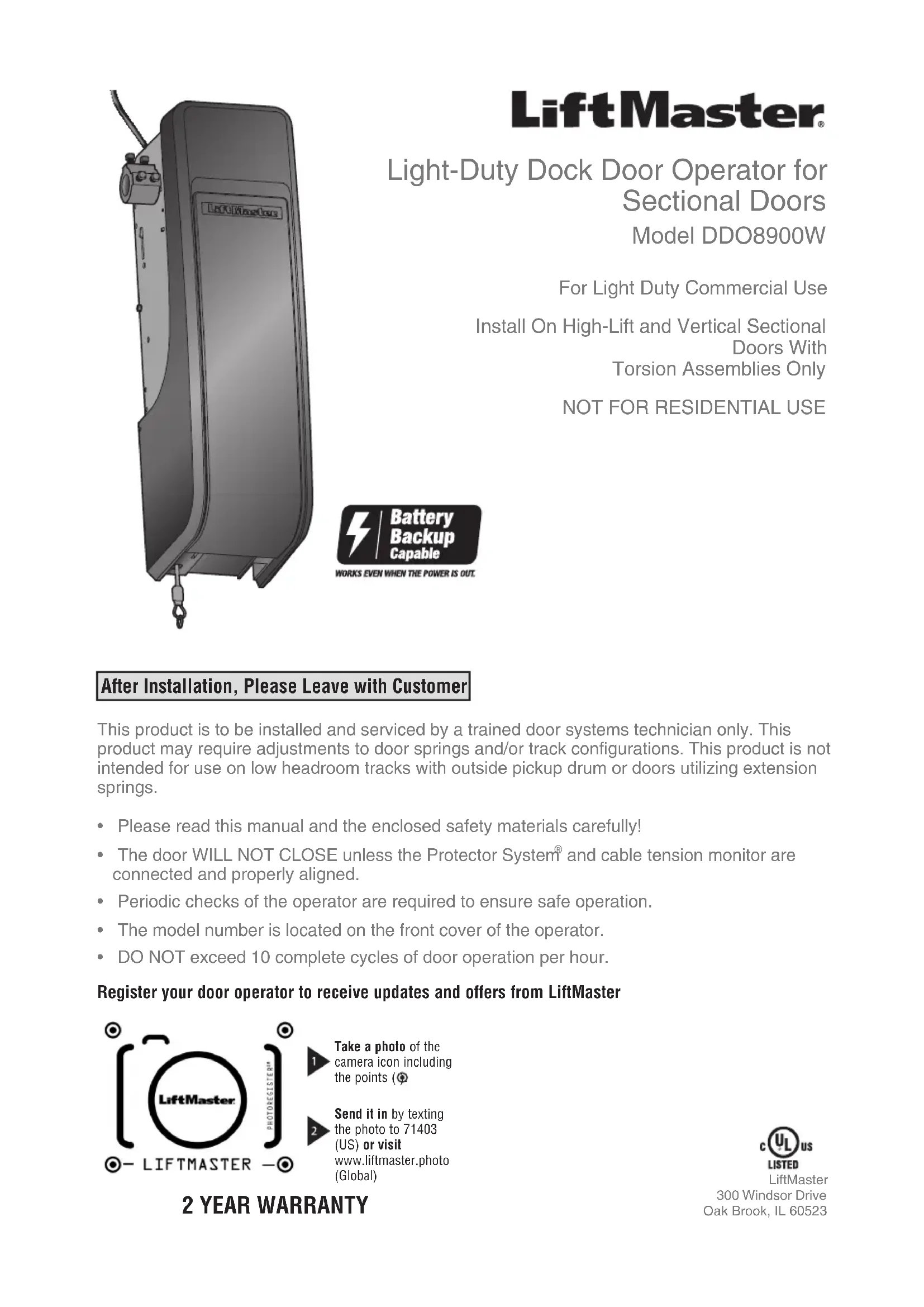
USER MANUAL DDO8900W LIFT-MASTER
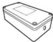
natural_image
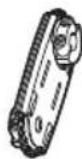
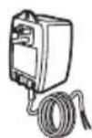
Illustration of a portable industrial device with attached control panel and hanging hook (no text or symbols)LiftMaster®
Light-Duty Dock Door Operator for
Sectional Doors
Model DDO8900W
For Light Duty Commercial Use
Install On High-Lift and Vertical Sectional
Doors With
Torsion Assemblies Only
NOT FOR RESIDENTIAL USE
After Installation, Please Leave with Customer
This product is to be installed and serviced by a trained door systems technician only. This product may require adjustments to door springs and/or track configurations. This product is not intended for use on low headroom tracks with outside pickup drum or doors utilizing extension springs.
- Please read this manual and the enclosed safety materials carefully!
- The door WILL NOT CLOSE unless the Protector System® and cable tension monitor are connected and properly aligned.
• Periodic checks of the operator are required to ensure safe operation. - The model number is located on the front cover of the operator.
• DO NOT exceed 10 complete cycles of door operation per hour.
Register your door operator to receive updates and offers from LiftMaster

text_image
LiftMaster PHOTOBOXISTERM - LIFTMASTER -Take a photo of the camera icon including the points (
Send it in by texting the photo to 71403 (US) or visit www.liftmaster.photo (Global)
2 YEAR WARRANTY

LiftMaster
300 Windsor Drive
Oak Brook, IL 60523
Table of Contents
Introduction 2
Safety Symbol and Signal Word Review ...2
Planning....3
Preparing Your Door 4
Tools Needed 4
Carton Inventory 5
Hardware 5
Additional Items You May Need......5
Terminal Block Wiring Layout....5
Assembly 6
Attach the Collar to the Door Operator .....6
Attach Mounting Bracket to
Door Operator....7
Installation 7
Position and Mount the Door Operator .....8
Attach the Emergency release 9
Install the Automatic Door Lock (Not Provided)....9
Attach the Cable Tension Monitor (Required)....10
Install the Three Button Control Station....11
Install the Protector System......12
Install the Light Curtain (Not Provided)...15
Connect Power....16
Install the Battery Backup (Not Provided)....18
Install the LMi5 (Not Provided)....19
Adjustments 20
Program the Travel 20
Automatic Force Setup....20
Test the Safety Reversal System......21
Test the Protector System......21
Test Cable Tension Monitor 22
Test Automatic Door Lock....22
To Open the Door Manually .....22
Operation 23
Using Your Door Operator 24
Programming 25
Remote Control (Not Provided)......25
To Erase the Memory....25
Activating Timer-To-Close (TTC)......26
Maintenance 26
Care of Your Door Operator 26
Troubleshooting 27
Diagnostic Chart 27
Additional Troubleshooting .....28
Repair Parts 30
Installation Parts 30
Door Operator Parts....30
Accessories 31
Contact Information 31
Introduction
Safety Symbol and Signal Word Review
This door operator has been designed and tested to offer safe service provided it is installed, operated, maintained and tested in strict accordance with the instructions and warnings contained in this manual.
When you see these Safety Symbols and Signal Words on the following pages, they will alert you to the possibility of serious injury or death if you do not comply with the warnings that accompany them. The hazard may come from something mechanical or from electric shock. Read the warnings carefully.
When you see this Signal Word on the following pages, it will alert you to the possibility of damage to your door and/or the door operator if you do not comply with the cautionary statements that accompany it. Read them carefully.
WARNING
Mechanical
WARNING
Electrical
CAUTION

WARNING: This product can expose you to chemicals including lead, which are known to the State of California to cause cancer or birth defects or other reproductive harm. For more information go to www.P65Warnings.ca.gov.
Introduction
Planning
Survey your area to see if any of the conditions below apply to your installation. Depending on your requirements, additional materials may be required.
THIS DOOR OPERATOR IS COMPATIBLE WITH:
- Doors that use a torsion bar and springs. The torsion bar must be 1" (2.5 cm) diameter. NOT compatible with reverse wound drums.
- 4-6" (10-15 cm) drums and tapered drums up to 11" (28 cm) (high and vertical lift).
- High lift (up to 54" (137.2 cm) high) and full vertical lift sectional doors up to 14 ft. (4.3 m) high.
- Doors up to 18 ft. (5.5 m) wide.
- Doors up to 180 sq. ft. (16.7 sq. m).
- Doors up to 300lb (136.1 kg)
NOTE: The optional battery is recommended for doors from 250lbs to 300lbs to achieve best performance.
Review or inspect proposed installation area. The door operator can be installed on the left
or right side of door. Select the side that meets the requirements listed below.
a. Must have minimum of 2.5" (6.4 cm) between the wall and the center of the torsion bar.
b. Must have minimum of 3" (7.6 cm) between the ceiling and the center of torsion bar.
c. Must have minimum of 8.5" (21.6 cm) between the side wall (or obstruction) and the end of torsion bar.
d. The torsion bar must extend at least 1.5" (3.81 cm) past the bearing. This may vary depending on your installation requirements.
e. An electric outlet is required within 6 ft. (1.83 m) of the installation area. If outlet does not exist, contact a qualified electrician.
f. Depending upon building construction, operator mounting brackets, extension brackets or wood blocks may be needed to install safety reversing sensors and cable tension monitor.
g. If the torsion bar is out of round, or if the normal mounting location is obstructed, an alternative mounting kit (480LM) may be used (not included).
h. Alternate floor mounting of the safety reversing sensors will require additional hardware (not provided).
i. Check the seal on the bottom of the door. Any gap between the floor and the bottom of the door must not exceed 1/4 inch (6 mm). Otherwise, the safety reversal system may not work properly.
C 8.5" (21.6 cm)
d Torsion bar
Wall or obstruction
e
Automatic door lock (Not provided)
Safety reversing sensor
NOTE: Inspect the torsion bar while the door is raised and lowered. It is important that there is no noticeable movement up and down or left and right. If the movement is not corrected, the life of the door operator will be greatly reduced.
b 3" (7.6 cm)
a
2.5" (6.4 cm)
Torsion bar
Smart LED Light (Not provided)
Door spring
g
f
h
Preparing Your Door
BEFORE YOU BEGIN:
- Disable locks.
- Remove any ropes connected to the door.
Complete the following test to make sure the door is balanced and is not sticking or binding:
- Lift the door halfway up. Release the door. If balanced, it should stay in place, supported entirely by its springs.
- Raise and lower the door to check for binding or sticking.
- Door should NOT open or fall rapidly. If your door binds, sticks, or is out of balance, call a trained door systems technician.
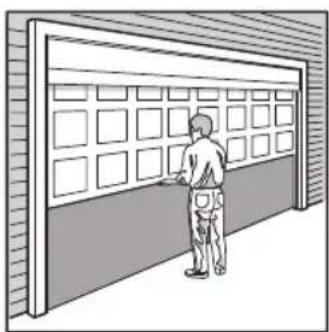
natural_image
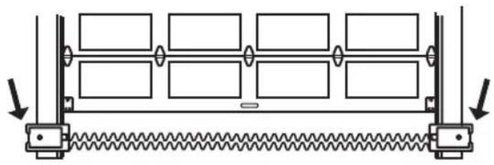
Illustration of a person standing beside a large wall with grid panels (no text or symbols visible)Sectional Door
WARNING
To prevent possible SERIOUS INJURY or DEATH:
- ALWAYS call a trained door systems technician if door binds, sticks, or is out of balance. An unbalanced door may NOT reverse when required.
- NEVER try to loosen, move or adjust door, door springs, cables, pulleys, brackets or their hardware, ALL of which are under EXTREME tension.
- Disable ALL locks and remove ALL ropes connected to door BEFORE installing and operating door operator to avoid entanglement.
CAUTION
To prevent damage to door and operator:
- ALWAYS disable locks BEFORE installing and operating the operator.
- ONLY operate door operator at 120V, 60 Hz to avoid malfunction and damage.
- DO NOT exceed 10 complete cycles of door operation per hour.
SPECIFICATIONS
Volts 120 Vac - 60 Hz, ONLY
Current 2.0 AMPS
Light Duty Commercial Use Rated Load 10 Nm
LED Light (Not Provided) Current....0.2 AMPS
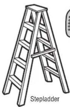
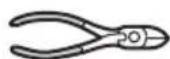
Tools Needed
During assembly, installation and adjustment of the door operator, instructions will call for hand tools as illustrated below.
natural_image
Line drawing of a wooden ladder with label 'Stepladder' below (no other text or symbols)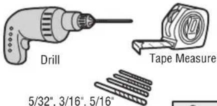
text_image
Drill Tape Measure 5/32", 3/16", 5/16"5/32", 3/16", 5/16" and 3/4" Drill Bits
Wire Cutters

Pliers
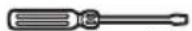
Screwdriver
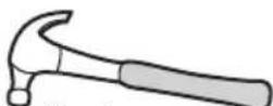
Claw Hammer

Level
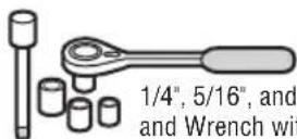
1/4", 5/16", and 3/8" Sockets and Wrench with 6" Extension
Adjustable End Wrench
Introduction
Carton Inventory
Your door operator is packaged in one carton which contains the motor unit and the parts illustrated below. If anything is missing, carefully check the packing material.
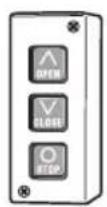
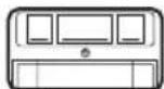
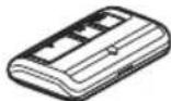
Three Button Control Station
natural_image
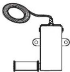
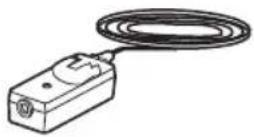
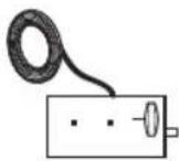
Simple line drawing of a mechanical or electrical component with a coiled cable and two ports (no text or symbols)Cable Tension Monitor with 2-Conductor Green/White Bell Wires
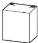
natural_image
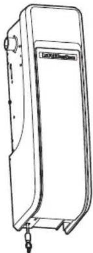
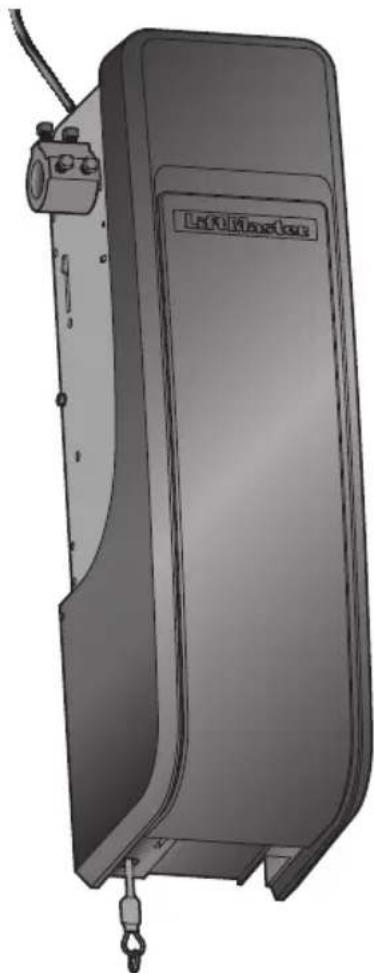
Line drawing of a mechanical device with a label on the front panel (no text or symbols on the device itself)Door Operator
The Protector System (2) Safety Reversing Sensors (1 Sending Sensor and 1 Receiving Sensor) with 2-Conductor White and White/Black Bell Wire attached
Emergency Release
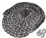
Sash Chain and
S-hooks (2)
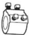
Collar with Set Screws

Mounting Bracket
Safety Reversing Sensor Bracket (2)
Safety Labels and Literature
NOT SHOWN
Quick User Guide
114A5055
Hardware
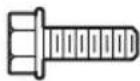
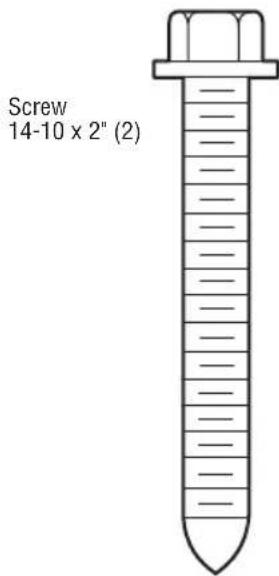
Screw #10-32 (2)
Screw 14-10x2" (4)
Screw 1/4"-20x1/2" (2)
Carriage Bolt 1/4"-20x1/2" (2)
Wing Nut 1/4"-20 (2)
Additional Items You May Need
Extension brackets (Model 041A5281-1) or wood blocks: Depending upon building construction, extension brackets or wood blocks may be needed to install the safety reversing sensor.
Fastening hardware: Alternate floor mounting of the safety reversing sensor will require hardware that is not provided.
LMi5 (Optional): May be required for LMi5 accessory installation
1/2" Cable Gland/Fittings (2)
Wire (14-24AWG, Solid recommended):
Wiring (optional) LMI5 accessory to DD08900W as well as additional sensor accessories.
90° connector for cable conduit or flex cable adapter: Required for permanent wiring.
Battery Backup (Model 485LM): The unit is battery backup compatible (battery not included). The battery can provide additional power during normal operation and backup power when the main power is out.
Automatic door lock (Model 841LM): The automatic door lock is used to prevent the door from being manually opened once the door is fully closed.
Smart LED Light (827LM): A wireless light that can program to the door operator or a remote control.
NOTE: If you are not installing a three button control station, please refer to the important note on page 11.
Terminal Block Wiring Layout
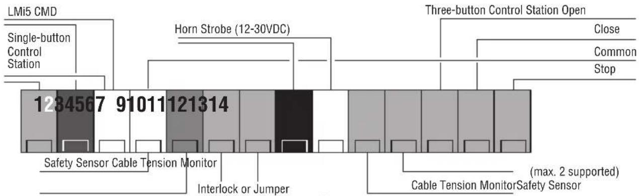
bar
| Category | Value | |---|---| | Single-button Control Station | 1284567 | | Horn Strobe (12-30VDC) | 910111 | | Three-button Control Station Open | 121314 | | Close | | | Common | | | Stop | | | Safety Sensor Cable Tension Monitor | | | Interlock or Jumper | | | Cable Tension Monitor | (max. 2 supported) | | Safety Sensor | | | Safety Sensor Cable Tension Monitor | |Assembly
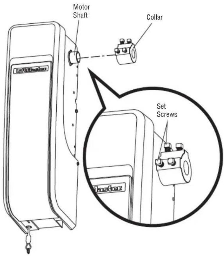
1 Attach the Collar to the Door Operator
To avoid installation difficulties, do not run the door operator until instructed to do so.
The door operator can be installed on either side of the door (see Planning section page 3). The illustrations shown are for installation on the left side.
- Loosen the set screws.
- Attach collar to the door operator motor shaft. The side of the collar with the larger hole should be placed on the motor shaft. Ensure that the collar is seated all the way on motor shaft until stop is reached.
- Position the collar so the screws are facing out and are accessible when attached to the torsion bar.
- Securely tighten the 2 square head set screws closest to the motor shaft by turning the screws 1/4 - 1/2 turn after making contact with the motor shaft.

WARNING
To prevent possible SERIOUS INJURY or DEATH, the collar MUST be properly tightened. The door may NOT reverse correctly or limits may be lost due to collar slip.
text_image
Motor Shaft Collar Set Screws MasterAssembly
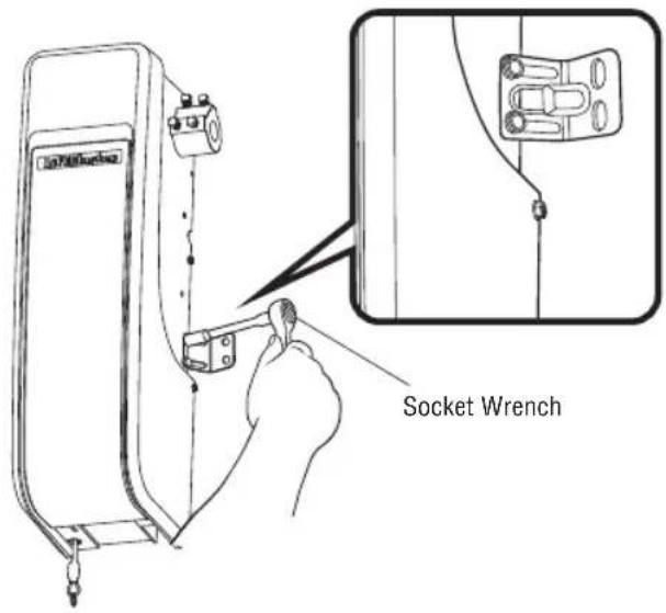
2 Attach Mounting Bracket to Door Operator
- Loosely attach slotted side of mounting bracket to the same side of the door operator as the collar, using screws provided.
NOTE: Do not tighten screws until instructed.
- It may be necessary to add additional material behind the operator to properly secure the mounting bracket when mounting the DDO8900W on larger drums.
text_image
Socket WrenchHARDWARE
Screw
10-32 (2)
Installation
IMPORTANT INSTALLATION INSTRUCTIONS
WARNING
To reduce the risk of SEVERE INJURY or DEATH:
- READ AND FOLLOW ALL INSTALLATION WARNINGS AND INSTRUCTIONS.
- Install door operator ONLY on properly balanced and lubricated door. An improperly balanced door may NOT reverse when required and could result in SEVERE INJURY or DEATH.
- ALL repairs to cables, spring assemblies and other hardware MUST be made by a trained door systems technician BEFORE installing operator.
- Disable ALL locks and remove ALL ropes connected to door BEFORE installing operator to avoid entanglement.
- Install the door operator at least 8 ft (2.44m) or more above the floor. If the operator must be installed less than 8 ft (2.44m) above the floor, then exposed moving parts must be protected by covers or guarding, provided by the operator manufacturer.
-
Mount the emergency release within reach, but at least 6 feet (1.83 m) above the floor and avoiding contact with vehicles to avoid accidental release.
-
NEVER connect door operator to power source until instructed to do so.
- NEVER wear watches, rings or loose clothing while installing or servicing operator. They could be caught in door or operator mechanisms.
- Install wall-mounted door control:
• within sight of the door.
- out of reach of children at a minimum height of 5 feet (1.5 m) above floors, landings, steps or any other adjacent walking surface.
• away from ALL moving parts of the door.
-
Install the Emergency Release Marking. Attach the marking on or next to the emergency release. Install the Entrapment Warning Placard next to the door control in a prominent location.
-
Place emergency release/safety reverse test label in plain view on inside of door.
Installation
1 Position and Mount the Door Operator
NOTE: For additional mounting options refer to the accessories page.
- Close the door completely.
- Slide the door operator onto the end of the torsion bar. If the torsion bar is too long or damaged, you may need to cut the torsion bar.
Ensure the collar does NOT touch the bearing.
- Use a level to position and vertically align the door operator. Verify the mounting bracket is located on a solid surface such as wood, concrete or door/flag bracket. If installing on drywall, the mounting bracket MUST be attached to a stud.
- When the door operator is properly aligned, mark the mounting bracket holes. If necessary, tighten collar screws on the torsion bar to hold door operator in place while marking holes.
NOTE: The door operator does not have to be flush to wall.
- Remove the door operator from torsion bar. Drill 3/16" pilot holes at the marked locations. Drill through metal door rail plates if necessary.
- Slide the door operator back onto the torsion bar until pilot holes align with bracket.
- Tighten the 2 square head set screws on the torsion bar. For a hollow torsion bar, tighten screws 3/4 - 1 full turn after making contact with the bar. For a solid shaft torsion bar, tighten screws 1/4 - no more than 1/2 turn after making contact with the shaft. If installing on a keyed torsion bar, DO NOT tighten the screws into the keyway.
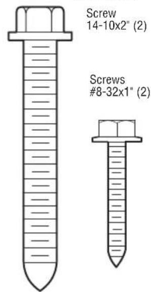
- Secure the mounting bracket to the wall and to the door operator. Use the 14-10x2" screws to secure the mounting bracket to the wall.

WARNING
To prevent possible SERIOUS INJURY or DEATH:
• Concrete anchors MUST be used if mounting bracket into masonry.
- NEVER try to loosen, move or adjust door, springs, cables, pulleys, brackets or their hardware, ALL of which are under EXTREME tension.
- ALWAYS call a trained door systems technician if door binds, sticks or is out of balance. An unbalanced door might NOT reverse when required.
- Operator MUST be mounted at a right angle to the torsion bar to avoid premature wear on the collar.
HARDWARE
text_image
Screw 14-10 x 2" (2)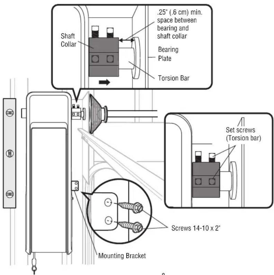
text_image
Shaft Collar .25" (.6 cm) min. space between bearing and shaft collar Bearing Plate Torsion Bar Set screws (Torsion bar) Screws 14-10 x 2" Mounting BracketInstallation
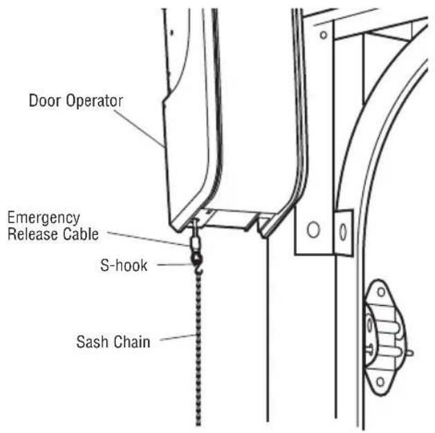
2 Attach the Emergency Release
- Attach the sash chain to the emergency release cable, using an S-hook. Mount the sash chain within reach, but at least 6 feet (1.83 m) above floor, avoiding contact with vehicles to prevent accidental release.
text_image
Door Operator Emergency Release Cable S-hook Sash Chain
WARNING
To prevent possible SERIOUS INJURY or DEATH from a falling door:
- If possible, use emergency release to disengage door ONLY when door is CLOSED. Weak or broken springs or unbalanced door could result in an open door falling rapidly and/or unexpectedly.
- NEVER use emergency release unless doorway is clear of persons and obstructions.
HARDWARE

text_image
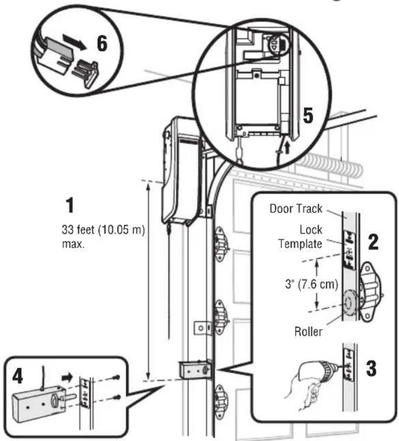
Sash Chain S-hooks (2)3 Install the Automatic Door Lock (Not Provided)
The automatic door lock (model 841LM) is used to prevent the door from being manually opened once the door is fully closed, see Accessories page 31.
HARDWARE
Screw 1/4"-20x1/2" (2)
NOTE: Older model 24 V door locks are incompatible.
- The lock has a 33' (10 m) cord and may be mounted on either side of the door. The third roller from the bottom is ideal for most installations.
- Ensure rail surface is clean and attach the lock template to the track so that the bolt hole is approximately 3" (7.6 cm) from the center of a door roller.
- Drill holes as marked on the template.
- Fasten automatic door lock to the outside of the door track with hardware provided.
- Run bell wire up wall to door operator. Use insulated staples to secure wire in several places. Insert wire through the bottom of the door operator.
- Plug the connector into either plug in the door operator.
A secondary door lock can be installed on the opposite side of the door following the instructions above.
text_image
6 1 33 feet (10.05 m) max. 4 5 Door Track Lock Template 2 3" (7.6 cm) Roller 34 Attach the Cable Tension Monitor (Required)
NOTE: The cable tension monitor is shipped for left side installation. It is recommended that the cable tension monitor be installed on the same side of the door as the door operator. For right side installation, remove the snap-ring holding the roller in place and reassemble it on the opposite side of the cable tension monitor.
- Make sure the door cable is approximately 3/4" (19 mm) from the mounting surface. Door adjustments or shimming may be required to achieve proper depth for the door cable.
- Position the cable tension monitor no more than 6' (2 m) above the door opening, and be sure the roller extends 1/8"-1/4" past the cable. Make sure cable tension monitor is located over a wood support member and the roller is free from any obstructions.
NOTE: There must be no obstructions in the installation area that prevent the cable tension monitor from closing completely when slack is detected.
-
Mark and drill 3/16" pilot holes for screws (pilot holes are not required for anchors).
-
Attach the cable tension monitor to the wall using the hardware provided. Make sure that the roller is on top of the cable.
-
Run bell wire to door operator. Use insulated staples to secure wire.
-
Connect bell wire to the green quick-connect terminals on the door operator (polarity is not important).
NOTE: Cable must have tension through entire door travel. Make sure there is no slack in cable on opposite side of door during normal operation. If slack occurs during door travel, adjust cables as required.
A second cable tension monitor may be installed for additional security. When two cable tension monitors are installed, the door will not move in the down direction or will reverse if one of the monitors detects slack or is disconnected.
If one of the cable tension monitors is removed, unplug both monitors from the operator. Then plug in the monitor you wish to use and unplug and plug in the operator three times to relearn the monitor to the operator.
The cable tension monitor MUST be connected and properly installed before the door operator will move in the down direction.
The cable tension monitor detects ANY slack that may occur in the cables and will reverse the door, eliminating service calls.
HARDWARE
text_image
Screw 14-10x2" (2) Screws #8-32x1" (2)
text_image
(To door operator) To insert or release wire, push in tab with screwdrivertip WHT/ GRN 1413/2011098765A Cable Drum Cable Tension Monitor 1/8"-1/4" (3-6 mm) Cable Tension Monitor Roller (To cable tension monitor)
text_image
Door Closed Door Open Wall Drum Approx. 3/4" (19 mm) Cable Tension Monitor Roller IMPORTANT: Roller must be placed no more than 6' (2 m) above door opening The position of the cable tension monitor will vary depending on the type of door and drum used. Drum Approx. 2.5" (63.5mm)5 Install the Three Button Control Station
Install door control within sight of door, out of reach of small children at a minimum height of 5 feet (1.5 m) above floors, landings, steps or any other adjacent walking surface, and away from ALL moving parts of door.
- Remove the control station cover.
- Fasten the control station to the wall at least 5' (1.5 m) above floors, landings, steps or any other adjacent walking surface. The installation surface must be smooth and flat.
- Select appropriate knockout and run the wires to the operator.
- Connect wires to the control station and replace the control station cover.
- Fasten the warning placards to the wall next to the three button control station.
NOTE: DO NOT connect the power and operate the door operator at this time. The door will travel to the full open position but will not return to the close position until the safety reversing sensors are connected and properly aligned. See page 12.
text_image
1234567891011121314 To insert or release wire, push in tab with screwdriver tip Three Button Control StationNOTE: If you are not installing the three button control station, you must install a jumper wire (not provided) between terminals 4 and 14. Operator will not run if there is not a 3 button control station or the jumper wire installed.
DO NOT EXCEED 10 DOOR OPERATIONS PER HOUR. FASTEN LABEL ADJACENT TO DOOR. NE PAS FAIRE FONCTIONNER LA PORTE PLUS DE 10 FOIS PAR HEURE. FIXER L'ÉTIQUETTE PRÈS DE LA PORTE.

WARNING
natural_image
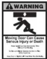
Silhouette of a person running with a downward arrow above (no text or symbols)Moving Door Can Cause Serious Injury or Death
Keep Clear! Door May Move at any Time Without Prior Warning
Do Not Let Children Operate the Door or Play in the Door Area
Keep Door in Sight at all Times When Door is Moving


WARNING
To prevent possible SERIOUS INJURY or DEATH from electrocution:
- Be sure power is NOT connected BEFORE installing door control.
- Connect ONLY to 24 VOLT low voltage wires.
To prevent possible SERIOUS INJURY or DEATH from a closing door:
• Install door control within sight of door, out of reach of children at a minimum height of 5 feet (1.5 m) above floors, landings, steps or any other adjacent walking surface, and away from ALL moving parts of door.
- NEVER permit children to operate or play with door control push buttons or remote controls.
- Activate door ONLY when it can be seen clearly, is properly adjusted and there are no obstructions to door travel.
• ALWAYS keep door in sight until completely closed. NEVER permit anyone to cross path of closing door.
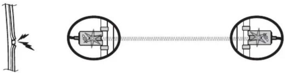
6 Install the Protector System
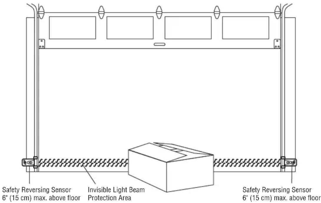
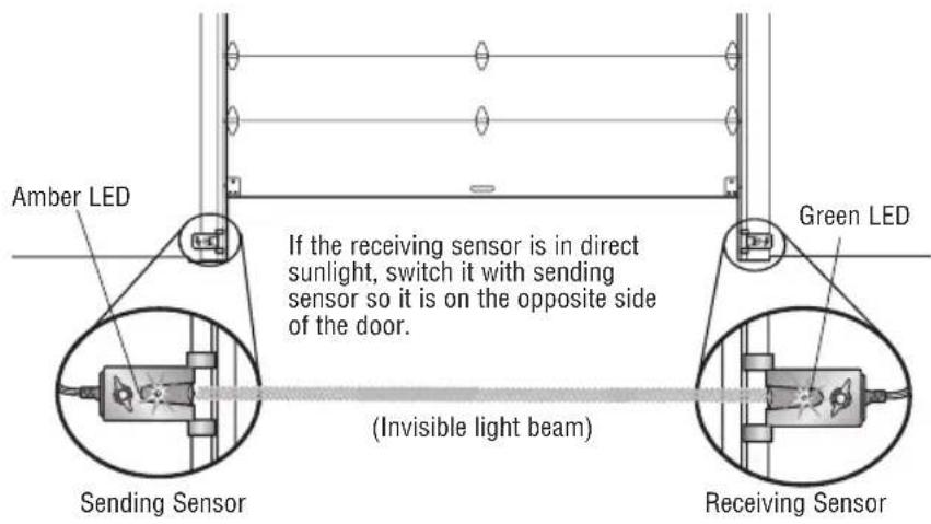
The safety reversing sensor must be connected and aligned correctly before the door will move in the down direction. This is a required safety device and cannot be disabled. The LiftMaster Light Curtain LC36A may be installed as an optional secondary safety device, see page 15.
IMPORTANT INFORMATION ABOUT THE SAFETY REVERSING SENSORS
When properly connected and aligned, the safety reversing sensor will detect an obstacle in the path of its electronic beam. The sending sensor (with an amber indicator light) transmits an invisible light beam to the receiving sensor (with a green indicator light). If an obstruction breaks the light beam while the door is closing the door will stop and reverse to the full open position.
The sensors must be installed inside the building so that the sending and receiving sensors face each other across the door, no more than 6" (15 cm) above the floor. Either can be installed on the left or right of the door as long as the sun never shines directly into the receiving sensor lens.
The mounting brackets are designed to clip onto the track of sectional doors without additional hardware.
If it is necessary to mount the sensors on the wall, the brackets must be securely fastened to a solid surface such as the wall framing. Extension brackets (see accessories) are available if needed. If installing in masonry construction, add a piece of wood at each location to avoid drilling extra holes in masonry if repositioning is necessary.
The invisible light beam path must be unobstructed. No part of the door (door tracks, springs, hinges, rollers or other hardware) may interrupt the beam while the door is closing.
WARNING
Be sure power is NOT connected to the door operator BEFORE installing the safety reversing sensor.
To prevent SERIOUS INJURY or DEATH from a closing door:
- Correctly connect and align the safety reversing sensor. This required safety device MUST NOT be disabled.
• Install the safety reversing sensor so beam is NO HIGHER than 6" (15 cm) above floor.
text_image
Safety Reversing Sensor 6" (15 cm) max. above floor Invisible Light Beam Protection Area Safety Reversing Sensor 6" (15 cm) max. above floorFacing the door from inside the building.
NOTE: If the LC36M/LC36M41 Monitored Light Curtain is used in place of Protector System Safety Reversing Sensors, please use the Installation Instructions that are provided with the LC36M/LC36M41.
INSTALLING THE BRACKETS
Be sure power to the operator is disconnected. Install and align the brackets so the safety reversing sensors will face each other across the door, with the beam no higher than 6" (15 cm) above the floor. Choose one of the following installations.
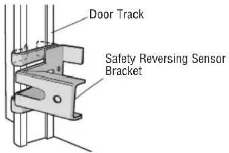
OPTION A: TRACK INSTALLATION
- Slip the curved arms over the rounded edge of each door track, with the curved arms facing the door. Snap into place against the side of the track. It should lie flush, with the lip hugging the back edge of the track, as shown.
If your door track will not support the bracket securely, wall installation is recommended.
text_image
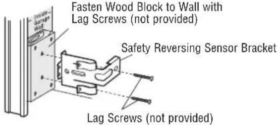
Door Track Safety Reversing Sensor BracketOPTION B: WALL INSTALLATION
- Place the bracket against the wall with curved arms facing the door. Be sure there is enough clearance for the sensor beam to be unobstructed.
- If additional depth is needed, an extension bracket (see Accessories) or wood blocks can be used.
- Use bracket mounting holes as a template to locate and drill (2) 3/16" diameter pilot holes on the wall at each side of the door, no higher than 6" (15 cm) above the floor.
- Attach brackets to wall with lag screws (not provided).
If using extension brackets or wood blocks, adjust right and left assemblies to the same distance out from the mounting surface. Make sure all door hardware obstructions are cleared.
text_image
Fasten Wood Block to Wall with Lag Screws (not provided) Safety Reversing Sensor Bracket Lag Screws (not provided)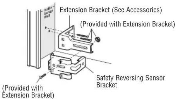
text_image
Extension Bracket (See Accessories) (Provided with Extension Bracket) Safety Reversing Sensor Bracket (Provided with Extension Bracket)OPTION C: FLOOR INSTALLATION
- Use wood blocks or extension brackets (see Accessories) to elevate sensor brackets so the lenses will be no higher than 6" (15 cm) above the floor.
- Carefully measure and place right and left assemblies at the same distance out from the wall. Be sure all door hardware obstructions are cleared.
- Fasten to the floor with concrete anchors as shown.
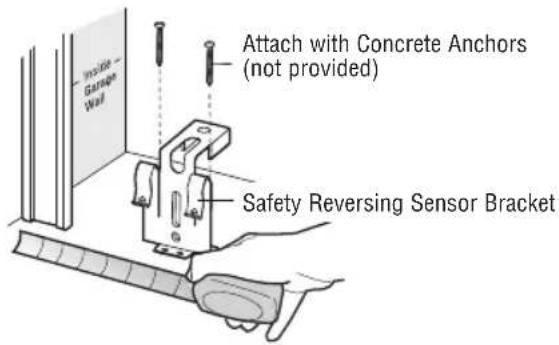
text_image
Attach with Concrete Anchors (not provided) Safety Reversing Sensor BracketMOUNTING THE SAFETY REVERSING SENSORS
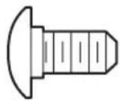
- Slide a 1/4"-20x1/2" carriage bolt head into the slot on each sensor.
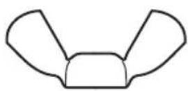
- Use wing nuts to fasten safety reversing sensors to brackets, with lenses pointing toward each other across the door. Be sure the lens is not obstructed by a bracket extension.
- Finger tighten the wing nuts.
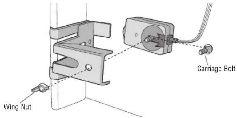
text_image
Wing Nut Carriage BoltHARDWARE
Carriage Bolt 1/4"-20x1/2" (2)
Wing Nut 1/4"-20 (2)
WIRE THE SAFETY REVERSING SENSORS
- Run the wire from both sensors to the door operator. Attach the wire to the wall and ceiling with the staples.
- Strip 7/16" (11 mm) of insulation from each set of wires. Separate the wires. Twist the white wires together. Twist the white/black wires together.
- Insert the white wires into the white terminal on the door operator. Insert the white/black wires into the grey terminal on the door operator. To insert or remove the wires from the terminal, push in the tab with a screwdriver tip.
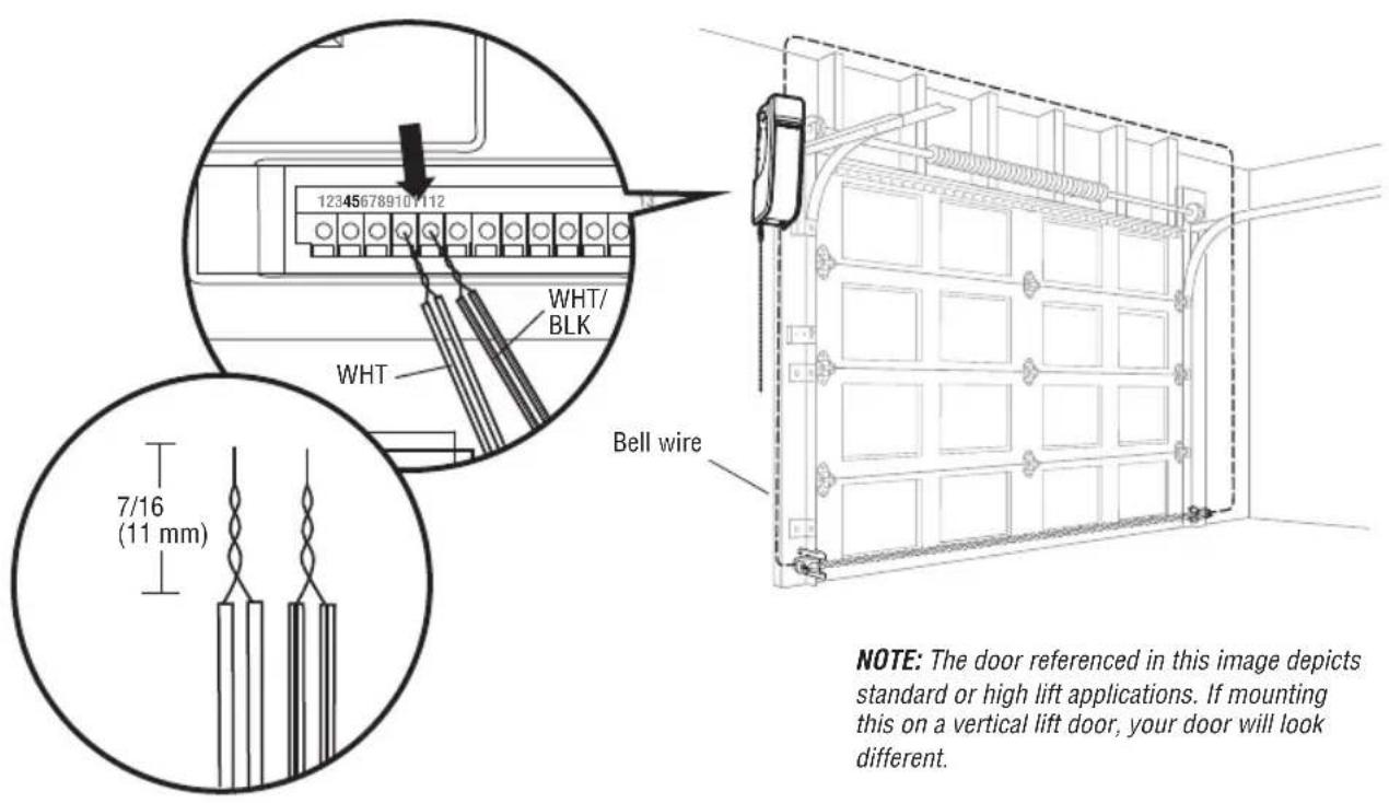
text_image
12345678910/112 WHT/ BLK WHT Bell wire 7/16 (11 mm) NOTE: The door referenced in this image depicts standard or high lift applications. If mounting this on a vertical lift door, your door will look different.NOTE: The door referenced in this image depicts standard or high lift applications. If mounting this on a vertical lift door, your door will look different.
7 Install the Light Curtain (Not Provided)
The following are general instructions for a typical installation, refer to the complete instructions included with the Light Curtain.
The plug-in power supply accessory (model 100MAPS) is required to power the Light Curtain. LiftMaster Light Curtain (Model LC-36A) is an ancillary entrapment protection device designed with 8 optical sensors that form 22 total invisible light beams which create a cross-pattern or netting effect for maximum protection against entrapment. If an obstruction breaks any light beam while the door is closing, the operator will stop and reverse to the full open position. The Light Curtain Transmitter must be installed facing the Light Curtain Receiver across the entrapment zone, 12" (30.5 cm) above the primary monitored entrapment protection device. The minimum installation width is 3 ft. (.91 m) and the maximum width is 33 ft. (10 m).
NOTE: Ensure that no part of the door, door tracks, springs, hinges, rollers, cords or other hardware interrupts the light beam while the door is closing.
INSTALLATION
- Fasten the mounting brackets loosely to both Light Curtains with the screws provided.
- Measure a minimum of 12" above the safety reversing sensors. Mark this location. The Light Curtain must be installed above this point.
- Hold the Light Curtain up to the desired mounting location with the cable end pointing upward. Secure the bottom mounting bracket to the mounting surface. The mounting brackets must be securely fastened to a solid surface such as a wall framing.
- Make sure the Light Curtain is level and secure the upper mounting bracket to the mounting surface.
- Tighten the screws to secure the Light Curtain to the mounting bracket.
- Secure the other Light Curtain to the opposite side of the door following steps 2 - 5, making sure they are aligned.
WIRING
NOTE: Complete all wiring of the light curtain to the operator BEFORE adding power to ensure the light curtain is not damaged.
Transmitting Light Curtain:
- White Wire to white terminal on door operator
- Black Wire to gray terminal on door operator
Transmitting and Receiving Light Curtains:
- Brown Wire (+) to White/Black on power supply
- Blue Wire (-) to Black on power supply
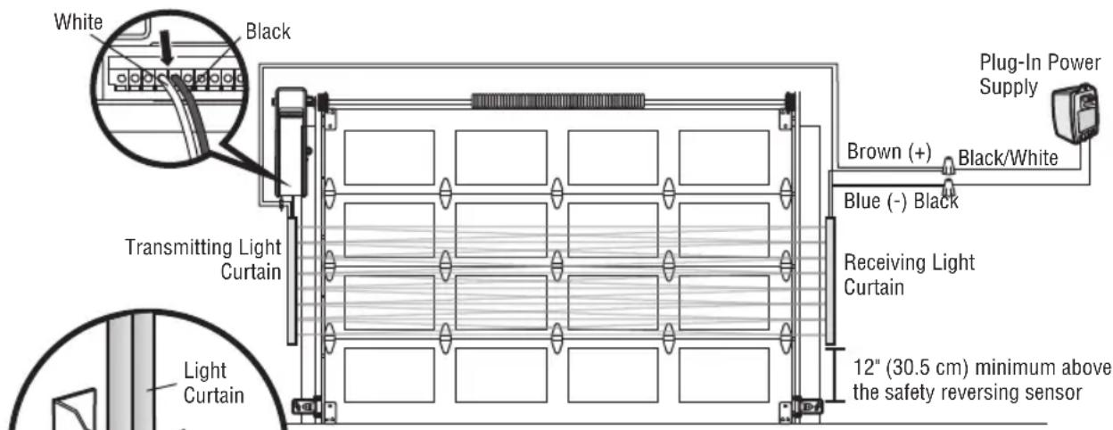
text_image
White Black Transmitting Light Curtain Light Curtain 12" (30.5 cm) minimum above the safety reversing sensor Receiving Light Curtain Brown (+) Black/White Blue (-) Black Plug-In Power SupplyNOTE: Aside from height above floor the LC36M/LC36M41 Monitored Light Curtain mounting is identical to the LC-36A mounting. Please use the Installation Instructions that are provided with the LC36M/LC36M41.
WARNING
To prevent possible SERIOUS INJURY or DEATH from a closing door:
- Be sure to DISCONNECT POWER to the operator BEFORE installing the Light Curtain.
- The door MUST be in the fully opened or closed position BEFORE installing the Light Curtain.
- Correctly connect and align the Light Curtain transmitter and receiver.
- The Light Curtain is for use with LiftMaster Commercial Doors. Use with ANY other product voids the warranty.
- DO NOT use this product for the protection of dangerous machinery or in explosive atmospheres or radioactive environments. Use ONLY specific and approved types of devices for such applications.
- The Light Curtain MUST be installed ONLY by authorized and fully trained personnel.
- LiftMaster Monitored Entrapment Protection devices are required in addition to the Light Curtain. The Light Curtain may NOT be used as the sole entrapment protection device for ANY entrapment zone.
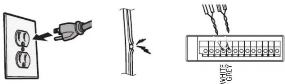
8 Connect Power
To avoid installation difficulties, do not run the door operator at this time.
To reduce the risk of electric shock, your door operator has a grounding type plug with a third grounding pin. This plug will only fit into a grounding type outlet. If the plug doesn't fit into the outlet you have, contact a qualified electrician to install the proper outlet.
There are two options for connecting power:
WARNING
To prevent possible SERIOUS INJURY or DEATH from electrocution or fire:
- Be sure power is NOT connected to the operator, and disconnect power to circuit BEFORE removing cover to establish permanent wiring connection.
- Door installation and wiring MUST be in compliance with ALL local electrical and building codes.
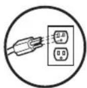
- NEVER use an extension cord, 2-wire adapter or change plug in ANY way to make it fit outlet. Be sure the operator is grounded.
OPTION A: TYPICAL WIRING
- Plug in the door operator into a grounded outlet.
- DO NOT run door operator at this time.
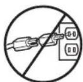
WRONGRIGHT
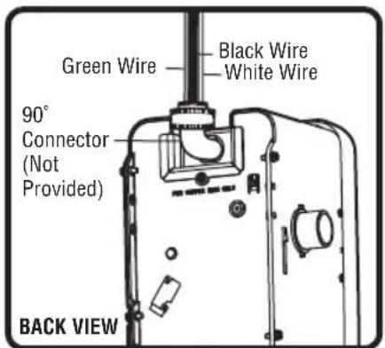
OPTION B: PERMANENT WIRING CONNECTION
If permanent wiring is required by your local code, refer to the following procedure.
To make a permanent connection through the 7/8" hole in the back of the door operator (according to local code):
- Be sure power is NOT connected to the door operator, and disconnect power to circuit.
- Remove the door operator from the torsion bar, remove cover screws and set the cover aside.
- Cut the line cord 6" (15.2 cm) above the strain relief.
- Squeeze the strain relief and push into motor unit, then remove the strain relief from the line cord.
- Install a 90° conduit (not provided) or flex cable adapter (not provided) to the 7/8" hole. Reinstall door operator to torsion bar.
- Run wires through conduit, cut to proper length and strip insulation.
- Strip 1/2" (1.3 cm) of insulation from the existing black, white and green wires.
- Connect the line to the black wire and neutral to the white wire with wire nuts (not provided). Connect ground wire to the green ground screw.
- Properly secure wires under plastic ties so that they do not come into contact with moving parts.
- Reinstall cover.
text_image
Green Wire Black Wire White Wire 90° Connector (Not Provided) BACK VIEW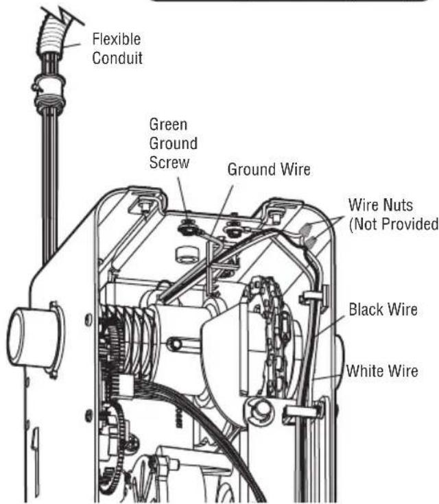
text_image
Flexible Conduit Green Ground Screw Ground Wire Wire Nuts (Not Provided) Black Wire White WireENSURE THE SAFETY REVERSING SENSORS (OR LIGHT CURTAIN) ARE ALIGNED
The door will not close if the sensors have not been installed and aligned correctly.
When the light beam is obstructed or misaligned while the door is closing, the door will reverse. If the door is already open, it will not close. The sensors can be aligned by loosening the wing nuts, aligning the sensors, and tightening the wing nuts.
- Check to make sure the LEDs in both sensors are glowing steadily. The LEDs in both sensors will glow steadily if they are aligned and wired correctly.
text_image
Amber LED Green LED If the receiving sensor is in direct sunlight, switch it with sending sensor so it is on the opposite side of the door. Sending Sensor (Invisible light beam) Receiving SensorIF THE AMBER LED ON THE SENDING SENSOR IS NOT GLOWING:
- Make sure there is power to the door operator. For LC36M/LC36M41, 100MAPS Power Supply is required. See LC36M/LC36M41 Installation Manual.
• Make sure the sensor wire is not shorted/broken. - Make sure that the sensor has been wired correctly. White wires to white terminal and white/black (or full black) wires to grey terminal.
text_image
WHITE GREYIF THE GREEN LED ON THE RECEIVING SENSOR IS NOT GLOWING:
• Make sure the sensor wire is not shorted/broken.
• Make sure the sensors are aligned.
natural_image
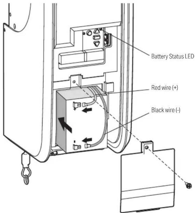
Pure electrical circuit lines without any symbols9 Install the Battery Backup (Not Provided)
When in Battery Backup mode, myQ® Smartphone Control and wireless myQ® devices will be disabled.
- Unplug the door operator.
- Use a Phillips head screwdriver to remove the battery cover on the door operator.
- Partially insert the battery into the battery compartment with the terminals facing out.
- Connect red (+) and black (-) wires from the door operator to the corresponding terminals on the battery.
- Replace the battery cover.
- Plug in the door operator.
BATTERY STATUS LED
Green LED:
All systems are normal.
- A solid green LED light indicates the battery is fully charged.
- A flashing green LED indicates the battery is being charged.
Orange LED:
The door operator has lost power and is in battery backup mode.
- A solid orange LED with beep, sounding approximately every 2 seconds, indicates the door operator is operating on battery power.
- A flashing orange LED with beep, sounding every 30 seconds, indicates the battery is low.
Red LED:
The door operator's 12V battery needs to be replaced.
- A solid red LED with beep, sounding every 30 seconds, indicates the 12V battery will no longer hold a charge and needs to be replaced. Replace the battery to maintain the battery backup feature.
NOTE: Battery does not have to be fully charged to activate the door operator.
text_image
Battery Status LED Red wire (+) Black wire (-)
WARNING
To reduce the risk of FIRE or INJURY to persons:
- Disconnect ALL electric and battery power BEFORE performing ANY service or maintenance.
- Use ONLY LiftMaster part # 485LM for replacement battery.
- DO NOT dispose of battery in fire. Battery may explode. Check with local codes for disposal instructions.

CAUTION
ALWAYS wear protective gloves and eye protection when changing the battery or working around the battery compartment.
10 Installing the Optional LMi5 Interface Accessory
The LMi5 accessory (not provided) provides the ability to monitor up to 5 sensors around the dock door with the myQ ^® Dock Management. These sensors provide the status of equipment to the myQ ^® Dock Management.
Typical sensors include:
PRE-SENSOR: This is a trailer presence sensor to provide status of whether a trailer is present at the dock or not.
WS-SENSOR: This is a mechanical roller limit switch to determine the status of a trailer restraint system or position of a dock leveler (deployed or stored)
WS-SENSOR-E: This is a photoelectrical sensor to determine the status of a trailer restraint system or position of a dock leveler (deployed or stored)
Once the sensors are connected to the LMi5, go to www.myQBusiness.com to set up your interface box configuration and name the connected sensors: (Normally Open/NO or Normally Closed/NC). The default status is Normally Open.
INSTALLATION
- Select a convenient location within 35' (10.6 m) of the operator to mount the LMi5 accessory.
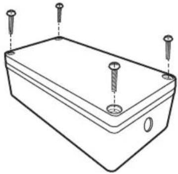
- Remove the 4 screws on the cover of the LMi5 and remove the cover (Figure 1)
- Add 12 " conduit connector or cable gland (not provided) to top and bottom holes of LMi5 per requirements of installation.
- Make wire connections (Figure 2) from CMD (Command) to Terminals 2 (red) and 3 (white) on the DDO8900W. Recommended: solid wire 14-24AWG. Route wiring through the top of LMi5.
- Press the SW1 button to learn the LMi5 to the operator. The LED should remain lit once learned.
- Make wire connections (Figure 2) from ACCY (Accessory) inputs to the sensors. Recommended: solid wire 14-24AWG. NOTE: Provide all required power externally – Accessory sensors cannot be powered from the LMi5 accessory. Route all wiring for the sensors to the center of the board and down through the bottom of the LMi5.
- Toggle the accessory device (switch the state of the contact). You should see the LED on the related LMi5 input change state in response.
- For wire retention of the various accessories, use the cutout near the bottom of the board (see Figure 2) in conjunction with a cable tie (not provided) to retain the various wires from the sensors.
- Secure the cover with the 4 screws provided.
WARNING
- Do not apply line voltage power directly to both terminals of each LMi5 input. An accessory must be connected as part of the circuit.
- The LMi5 should only be connected to dry contact switches/sensors, as it will not operate with open collector type devices.
- You may only connect ONE LMi5 Interface to a single dock door operator. Multiple LMi5 units are not supported.
Figure 1 LMi5 Interface Accessory
natural_image
Line drawing of a rectangular electronic enclosure with four screw holes and a central hole (no text or symbols)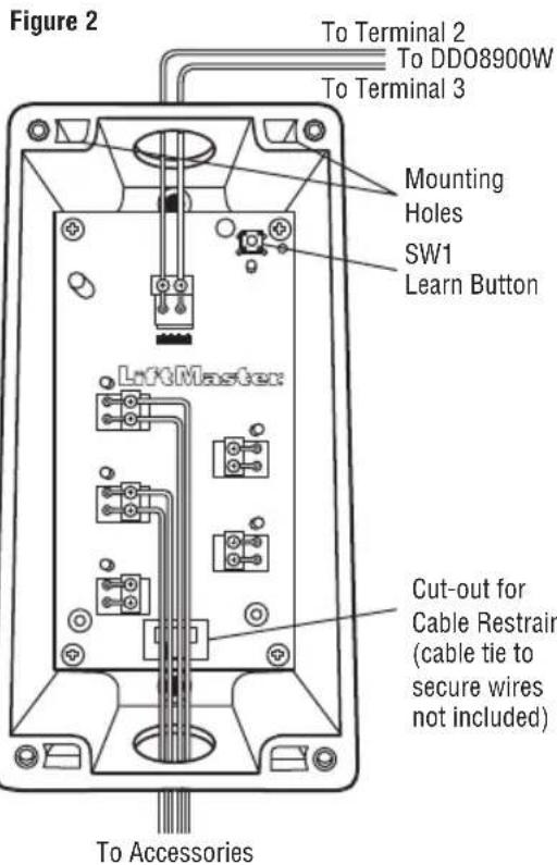
text_image
Figure 2 To Terminal 2 To DD08900W To Terminal 3 Mounting Holes SW1 Learn Button LiftMaster Cut-out for Cable Restrain (cable tie to secure wires not included) To AccessoriesAdjustments
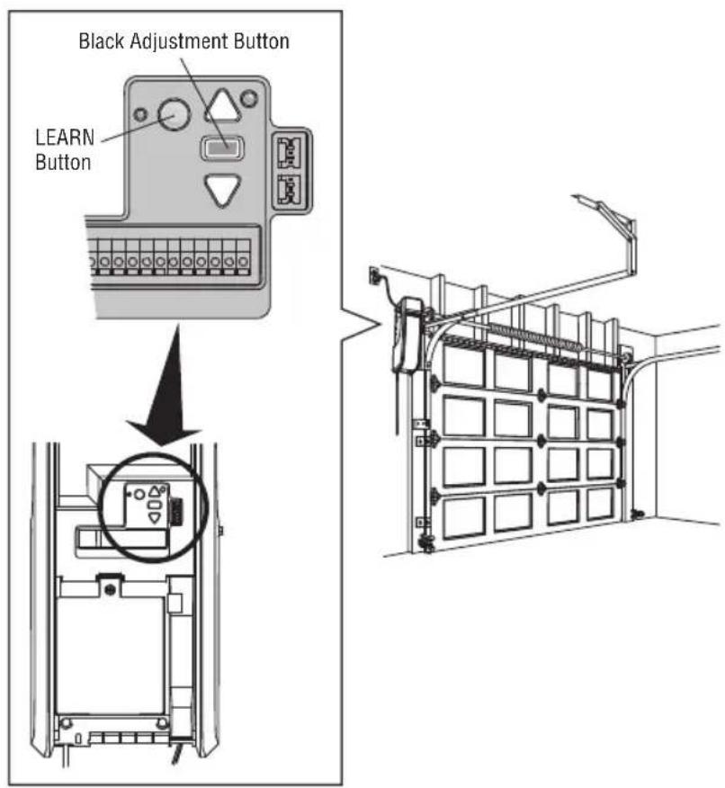
1 Program the Travel
Travel limits regulate the points at which the door will stop when moving up or down.
Note: While programming, the UP and DOWN buttons can be used to move the door as needed. During the Automatic Force Setup, the door will automatically open and close.
- Press and hold the Adjustment Button until the UP Button begins to flash and/or a beep is heard. The Safety Reversing Sensors will be disconnected during the Program the Travel process.
- Press and hold the UP Button until the door is in the desired UP position.
- Once the door is in the desired UP position press and release the Adjustment Button. The door operator will beep and the DOWN button will flash.
- Press and hold the DOWN Button until the door is in the desired DOWN position.
- Once the door is in the desired DOWN position press and release the Adjustment Button. The door operator will beep on short beep. Program the Travel is now complete. If the door operator beeps one long beep and the audible alert for the automatic force setup does not begin, the programming has timed out and travel limits have not been set. Please go back to Step 1 and Program the Limits.
WARNING
Without a properly installed safety reversal system, persons (particularly small children) could be SERIOUSLY INJURED or KILLED by a closing door.
- Incorrect adjustment of door travel limits will interfere with proper operation of safety reversal system.
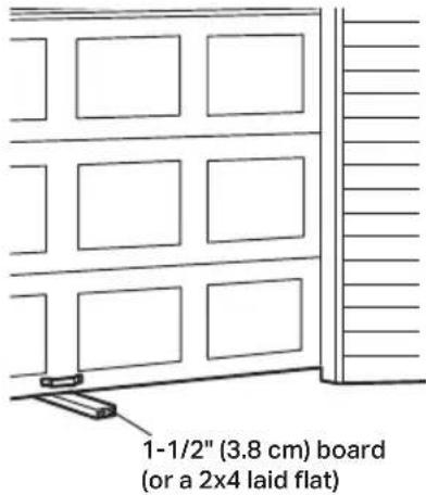
- After ANY adjustments are made, the safety reversal system MUST be tested. Door MUST reverse on contact with 1-1/2" high (3.8 cm) object (or 2x4 laid flat) on floor.
CAUTION
To prevent damage to vehicles, be sure fully open door provides adequate clearance.
2 Automatic Force Setup
- Once both the up and down positions have been manually set, the Safety Reversing Sensors will reconnect and become operational. Then, the door operator will enter a force-sensing operation by automatically moving the door open and close. The door operator will sound an audible alert before automatically opening and closing the door. The door operator will beep three times, confirming that the Automatic Force Setup completed successfully. Adjustment is complete.
- If you hear one long beep after the door attempts to move, then the Automatic Force Set Up has not completed successfully. Please start over at step 1 of Program the Travel.
If you are unable to program the travel:
- Ensure the cable tension monitor is correctly installed (see page 10).
- Check to see if the safety reversing sensors are misaligned or obstructed (refer to page 17). When the sensors are aligned and unobstructed, cycle the door through a complete up and down cycle using the remote control or the UP and DOWN buttons. If you are unable to operate the door up and down, repeat the steps above.
text_image
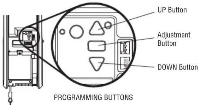
UP Button Adjustment Button DOWN Button PROGRAMMING BUTTONS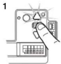
text_image
1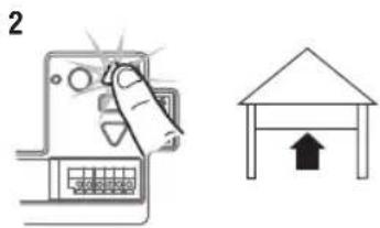
text_image
2
text_image
3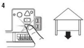
text_image
4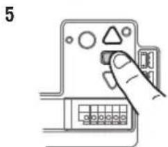
natural_image
Hand inserting a component into a device panel (no text or symbols visible)Adjustments
3 Test the Safety Reversal System
TEST
- With the door fully open, place a 1-1/2" (3.8 cm) board (or a 2x4 laid flat) on the floor, centered under the door.
- Operate the door in the down direction. The door MUST reverse when it makes contact with the board.
ADJUST
If the door stops but does not reverse:
- Review the installation instructions provided to insure all steps were followed;
- Repeat Program the Travel (see Adjustment Step 1);
- Repeat the Safety Reversal test. If the test continues to fail, call a trained door systems technician.
IMPORTANT SAFETY CHECK:
Test the Safety Reverse System after:
• Each adjustment of limits.
- Any repair to or adjustment of the door (including springs and hardware).
• Any repair to or buckling of the floor.
- Any repair to or adjustment of the operator.
WARNING
Without a properly installed safety reversal system, persons (particularly small children) could be SERIOUSLY INJURED or KILLED by a closing door.
- Safety reversal system MUST be tested every month.
- After ANY adjustments are made, the safety reversal system MUST be tested. Door MUST reverse on contact with 1-1/2" (3.8 cm) high object (or 2x4 laid flat) on the floor.
text_image
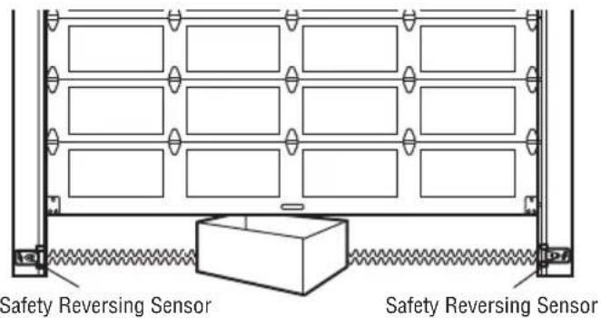
1-1/2" (3.8 cm) board (or a 2x4 laid flat)4 Test the Protector System
- Press the control station button to open the door.
- Place the operator carton in the path of the door.
- Press the control station button to close the door. The door will not move more than an inch (2.5 cm).
The door operator will not close from a control station if the indicator light in either sensor is off (alerting you to the fact that the sensor is misaligned or obstructed).
If the door operator closes the door when the safety reversing sensor is obstructed, do not operate the door. Call for a trained door systems technician.
WARNING
Without a properly installed safety reversing sensor, persons (particularly small children) could be SERIOUSLY INJURED or KILLED by a closing door.
text_image
Safety Reversing Sensor Safety Reversing SensorAdjustments
5 Test Cable Tension Monitor
- With the door fully closed, push on the front of the cable tension monitor. A click should be heard. If there is no click, the roller may be hitting the jamb and not allowing the switch to detect slack in the cable. Make sure the cable tension monitor is mounted flush with the mounting surface and the roller is free from any obstructions.
If your cable tension monitor has been activated the UP and DOWN arrows will flash diagnostic code 3-5, see page 27.
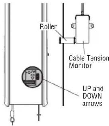
text_image
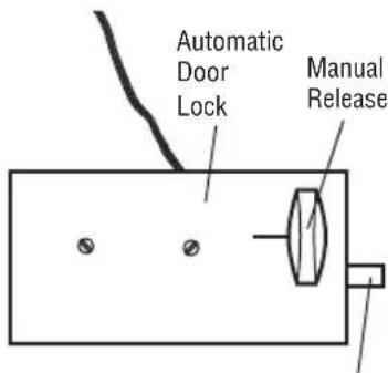
Roller Cable Tension Monitor UP and DOWN arrows6 Test Automatic Door Lock (Not Provided)
- With the door fully closed, the automatic door lock bolt should be protruding through the track.
- Operate the door in the open direction. The automatic door lock should retract before the door begins to move.
- Operate the door in the down direction. When the door reaches the fully closed position, the automatic door lock should move into lock position to secure the door.
NOTE: If the automatic door lock does not function, the lock can be manually released by sliding the manual release handle to the open position.
text_image
Automatic Door Lock Manual ReleaseLock Bolt "Locked"
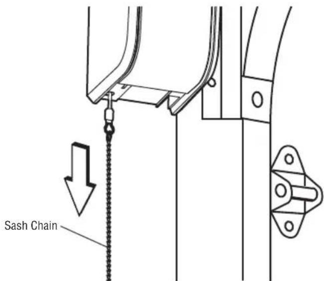
7 To Open the Door Manually
Disengage any door locks before proceeding. The door should be fully closed if possible. Pull down on the emergency release until a click noise is heard from the door operator and lift the door manually.
To reconnect the door to the door operator, pull the emergency release straight down a second time until a click noise is heard from the door operator. The door will reconnect on the next UP or DOWN operation.
TEST THE EMERGENCY RELEASE:
- Make sure the door is closed.
- Pull the emergency release. The door should then be able to be opened manually.
- Return the door to the closed position.
- Pull the sash chain a second time.
- Reconnect the door to the door operator.
WARNING
To prevent possible SERIOUS INJURY or DEATH from a falling door:
- If possible, use emergency release to disengage door ONLY when door is CLOSED. Weak or broken springs or unbalanced door could result in an open door falling rapidly and/or unexpectedly.
- NEVER use emergency release unless doorway is clear of persons and obstructions.
text_image
Sash ChainIMPORTANT SAFETY INSTRUCTIONS
WARNING
To reduce the risk of SEVERE INJURY or DEATH:
- READ AND FOLLOW ALL WARNINGS AND INSTRUCTIONS.
- ALWAYS keep remote controls out of reach of children. NEVER permit children to operate or play with door control push buttons or remote controls.
- ONLY activate door when it can be seen clearly, it is properly adjusted and there are no obstructions to door travel.
- ALWAYS keep door in sight and away from people and objects until completely closed. NO ONE SHOULD CROSS THE PATH OF THE MOVING DOOR.
- NO ONE SHOULD GO UNDER A STOPPED, PARTIALLY OPENED DOOR.
- If possible, use emergency release to disengage door ONLY when door is CLOSED. Use caution when using this release with the door open. Weak or broken springs or unbalanced door could result in an open door falling rapidly and/or unexpectedly and increasing the risk of SEVERE INJURY or DEATH.
- NEVER use emergency release unless doorway is clear of persons and obstructions.
-
After ANY adjustments are made, the safety reversal system MUST be tested. Failure to adjust the door operator properly may cause SEVERE INJURY or DEATH.
-
Safety reversal system MUST be tested every month. Door MUST reverse on contact with 1-1/2" (3.8 cm) high object (or a 2x4 laid flat) on the floor. Failure to adjust the door operator properly may cause SEVERE INJURY or DEATH.
- ALWAYS KEEP DOOR PROPERLY BALANCED (see page 4). An improperly balanced door may NOT reverse when required and could result in SEVERE INJURY or DEATH.
- ALL repairs to cables, spring assemblies and other hardware, ALL of which are under EXTREME tension, MUST be made by a trained door systems technician.
- To avoid SERIOUS PERSONAL INJURY or DEATH from electrocution, disconnect ALL electric and battery power BEFORE performing ANY service or maintenance.
- This door operator system is equipped with an unattended operation feature. The door could move unexpectedly. NO ONE SHOULD CROSS THE PATH OF THE MOVING DOOR.
- SAVE THESE INSTRUCTIONS.
Operation
Using Your Door Operator
FEATURES
Your door operator is equipped with features to provide you with greater control over your door operation.
myQ®
myQ ^ allows you to control your door operator from your mobile device or computer from anywhere. myQ ^ technology uses a 900Mhz signal to provide two way communication between the door operator and myQ ^ enabled accessories. The door operator has an internal gateway that allows the door operator to communicate directly with a home Wi-Fi network and access your myQ ^ account. Go to myQBusiness.com for more information.
THE PROTECTOR SYSTEM (SAFETY REVERSING SENSORS)
When properly connected and aligned, the safety reversing sensors will detect an obstruction in the path of the infrared beam. If an obstruction breaks the infrared beam while the door is closing, the door will stop and reverse to full open position. If the door is fully open, and the safety reversing sensors are not installed, or are misaligned, the door will not close from a remote control. However, you can close the door if you hold the button on the door control or keyless entry until the door is fully closed. The safety reversing sensors do not affect the opening cycle. For more information see page 12.
The door operator can be activated through a wall-mounted door control, remote control, wireless keyless entry or myQ ^® accessory. When the door is closed and the door operator is activated the door will open. If the door senses an obstruction or is interrupted while opening the door will stop. When the door is in any position other than closed and the door operator is activated the door will close. If the door operator senses an obstruction while closing, the door will reverse. However, you can close the door if you hold the button on the door control or keyless entry until the door is fully closed. The safety reversing sensors do not affect the opening cycle. The safety reversing sensor must be connected and aligned correctly before the door operator will move in the down direction.
BATTERY BACKUP (OPTIONAL)
The battery backup system allows access in and out of your building, even when the power is out. When the door operator is operating on battery power, the door operator will run slower, the Battery Status LED will glow solid orange, and a beep will sound approximately every 2 seconds.
NOTE: Wi-Fi capability will not be enabled when operating under Battery Backup conditions.
MEMORY CAPACITY
| SECURITY+ 2.0® ACCESSORIES MEMORY CAPACITY | |
| Remote Controls Up to 40 | |
| Keyless Entries Up to 3 | |
| Interface Boxes Up to 1 | |
| myQ® Accessories Up to 16 | |
Programming
Remote Control (Not Provided)
Up to 40 Security+ 2.0 remote controls can be programmed to the door operator. Older LiftMaster remote controls are NOT compatible, see page 31 for compatible accessories. To program additional accessories refer to the instructions provided with the accessory or visit LiftMaster.com. If your vehicle is equipped with a Homelink®, you may require an external adapter depending on the make, model, and year of your vehicle. Visit www.homelink.com for additional information.
To Erase the Memory
ERASE ALL REMOTE CONTROLS AND KEYLESS ENTRIES
- Press and hold the LEARN button on door operator until the learn LED goes out (approximately 6 seconds). All remote control and keyless entry codes are now erased.
Reprogram any accessory you wish to use.
ERASE ALL DEVICES (INCLUDING myQ® ENABLED ACCESSORIES)
- Press and hold the LEARN button on door operator until the learn LED goes out (approximately 6 seconds).
- Immediately press and hold the LEARN button again until the learn LED goes out. All codes are now erased.
Reprogram any accessory you wish to use.
ERASE THE Wi-Fi NETWORK FROM THE DOOR OPERATOR
Press and hold the black adjustment button until 3 beeps are heard (approximately 6 seconds).
text_image
Black Adjustment Button LEARN ButtonProgramming
Timer to Close (TTC) Activation:
TIMER TO CLOSE PROGRAMMING VIA THE OPERATOR:
- Press and release the yellow Learn button 4 times to activate the TTC programming mode.
- The yellow learn LED and UP Arrow will turn ON as an indication that the operator is in TTC programming mode.
- The operator can move between OFF/1/5/10 minutes increments using the UP and DOWN arrows. The yellow learn LED will blink corresponding to the number of minutes selected. For example, if the user selects 5 minutes, the yellow learn LED will blink 5 times.
- Press the rectangular adjustment button to save the setting and exit the TTC programming mode.
- The operator TTC programming mode will time out after 30 seconds unless the rectangular adjustment button is pressed. If the programming timer expires, the TTC will retain its previous setting.
- To Exit an uncompleted TTC programming session, press and release the learn button one more time to exit.
USER feedback If TTC timer is actively counting down: The last 10 seconds of timer to close provides audible alert from the operator. This cannot be turned off.
TTC TIMING CHANGE:
- Press the yellow learn button 4 times to activate the TTC programming mode.
- When reentering activation mode, TTC settings will be reset to OFF. For example, the existing timer is set to 5 minutes and the user wants to reset to 10 minutes. To do so, the user will need to press the UP button until the Learn LED blinks 10 times for 10 minutes.
TTC DEACTIVATION:
- Enter into TTC programming mode as described above.
- Press the rectangular adjustment button to save the setting.
TTC TEMPORARY SUSPENSION
- Timer can be suspended while in the open position by pressing the OPEN button during the 10 second TTC warning (audible beeping from the operator - 10 second countdown prior to TTC activation).
TTC OPERATION WITH IR SENSORS :
- The TTC feature will not be activated if IR sensors are not connected to the operator.
- If the TTC is active, the timer is counting down, and the IR beams are interrupted, the TTC timer will be restarted.
- If the door encounters an IR sensor obstruction while closing, it will reverse open and not close until the IR sensor obstruction has been cleared.
IF TTC is active, visual warnings can be added to alert bystanders before a door starts closing. See optional accessories.
TIMER TO CLOSE PROGRAMMING VIA AN OPTIONAL WALL CONTROL
- The 880LM LCD Control Panel or the 881LM Motion Detecting Control Panel with Timer to Close can be wired into the Red/White terminals as an optional control station. Both of these panels offer the Timer to Close feature. See instructions for wiring and programming TTC in the instruction manuals provided with those panels.
Maintenance
Care of Your Door Operator
MAINTENANCE SCHEDULE
Once a Month
- Manually operate door. If it is unbalanced or binding, call a trained door systems technician.
- Check to be sure door opens and closes fully. Adjust limits if necessary (see Adjustment Step 1).
- Repeat the safety reverse test. Make any necessary adjustments (see Adjustment Step 3).
Once a Year
• Oil door rollers, bearings and hinges. The door operator does not require additional lubrication. Do not grease the door tracks.
NOTICE: This device complies with Part 15 of the FCC rules and Industry Canada's license-exempt RSSs. Operation is subject to the following two conditions: (1) this device may not cause harmful interference, and (2) this device must accept any interference received, including interference that may cause undesired operation.
Any changes or modifications not expressly approved by the party responsible for compliance could void the user's authority to operate the equipment. This device must be installed to ensure a minimum 20 cm (8 in.) distance is maintained between users/bystanders and device.
This device has been tested and found to comply with the limits for a Class B digital device, pursuant to part 15 of the FCC rules and Industry Canada ICES standard. These limits are designed to provide reasonable protection against harmful interference in a residential installation. This equipment generates, uses and can radiate radio frequency energy and, if not installed and used in accordance with the instructions, may cause harmful interference to radio communications. However, there is no guarantee that interference will not occur in a particular installation. If this equipment does cause harmful interference to radio or television reception, which can be determined by turning the equipment off and on, the user is encouraged to try to correct the interference by one or more of the following measures:
- Reorient or relocate the receiving antenna.
- Increase the separation between the equipment and receiver.
- Connect the equipment into an outlet on a circuit different from that to which the receiver is connected.
- Consult the dealer or an experienced radio/TV technician for help.
Troubleshooting
Diagnostic Chart
Your door operator is programmed with self-diagnostic capabilities. The UP and DOWN arrows on the door operator flash the diagnostic codes.
text_image
UP Button DOWN Button| DIAGNOSTIC CODE DIAGNOSTIC CODE SOLUTION | |||
| Up Arrow Down ArrowFlash(es) Flash(es) | |||
| 1 1 The door operator will | not close. | Safety reversing sensors are not installed, connected or wires may be cut.Inspect sensor wires for a disconnected or cut wire. | |
| 1 2 The door operator will | not close. | There is a short or reversed wire for the safety reversing sensors. Inspectsensor wire at all staple points and connection points and replace wire orcorrect as needed. | |
| 1 3 The door control will not function. | function. | The wires for the door control are shorted or the door control is faulty.Inspect sensor wire at all staple points and connection points and replacewire or correct as needed. | |
| 1 4 The door operator will | not close. | Safety reversing sensors are misaligned or were momentarily obstructed.Realign both sensors to ensure both LEDs are steady and not flickering.Make sure nothing is hanging or mounted on the door that would interruptthe sensor's path while closing. | |
| 1 5 Door moves 6-8" | (15-20 cm) stops or reverses. | Manually open and close the door. Check for binding or obstructions, suchas a broken spring or door lock, correct as needed. Check wiring connectionsat travel module and at the logic board. Replace travel module if necessary. | |
| No movement, only asingle click. | Manually open and close the door. Check for binding or obstructions, suchas a broken spring or door lock, correct as needed. Replace logic board ifnecessary. | ||
| Door operator humsfor 1-2 seconds nomovement. | Manually open and close the door. Check for binding or obstructions,such as a broken spring or door lock, correct as needed. Replace motor ifnecessary. | ||
| 1 6 Door coast after it has | come to a complete stop. | Program travel to coasting position or have door balanced by a trained technician. | |
| 2 1-5 No movement or sound. | Replace logic board. | ||
| 3 1 The door operator moveslightly, then stops | slightly, then stops | Activate the door operator again. If problem persists, replace logic board. | |
| 3 3 The battery status LED isconstantly flashing green. | is | Battery backup charging circuit error, replace logic board. | |
| 3 5 The door operator | will not close or door reverses during travel. | If two cable tension monitors were previously installed and one has beenremoved, unplug and plug in the operator three times to relearn the monitorto the operator. | |
| 4 1-4 Door is moving stops andor reverses. | and | Manually open and close the door. Check for binding or obstructions, suchas a broken spring or door lock, correct as needed. If the door is binding orsticking contact a trained door systems technician. If door is not binding orsticking attempt to reprogram travel (refer to page 20). | |
| 4 5 Door operator runs | approximately 6-8"(15-20 cm), stops and reverses. | Communication error to travel module. Check travel module connections,replace module if necessary. | |
| 4 6 The door operator will | not close. | Safety reversing sensors are misaligned or were momentarily obstructed.Realign both sensors to ensure both LEDs are steady and not flickering.Make sure nothing is hanging or mounted on the door that would interruptthe sensor's path while closing. | |
Troubleshooting
Additional Troubleshooting
The door operator doesn't operate from the single or three button control station:
- Check If the wires are loose or disconnected at each terminal of the single or 3 button control station as well as the operator terminals. If no 3 button control station is installed, please verify placement of the jumper between terminals 4 and 14. All wiring connections must be made or the door will not close.
- Does the door operator have power? Plug a lamp into the outlet. If it doesn't, check the fuse box or the circuit breaker. (Some outlets are controlled by a wall switch.)
- Have you disabled all door locks? Review installation instruction warnings on page 7.
- Are the wiring connections correct? Review Installation Step 5.
- Is there a build-up of ice or snow under the door? The door may be frozen to the ground. Remove any restriction.
- The door spring may be broken. Have it replaced (see page 3 for reference).
The door operator operates from the single or three button control station, but not from a remote control:
- Reprogram the remote control and replace the battery if necessary. Repeat with all remote controls.
The door opens and closes by itself:
- Be sure that all remote control push buttons are off.
- Remove the bell wire from the single button control station terminals and operate from the remote only. If this solves the problem, the single button control station is faulty, or there is an intermittent short in the wire. Replace the control station.
- Erase the memory and reprogram all remote controls (refer to the instructions provided with the remote control or visit LiftMaster.com).
The door doesn't open completely:
- Disable any door locks.
- Is something obstructing the door? Is it out of balance, or are the springs broken? Remove the obstruction or have a service technician repair the door.
The door opens but won't close:
- Check that cable tension monitor is correctly installed. If a second cable tension monitor has been removed, follow the instructions to relearn a single cable tension monitor (See Installation Step 4).
- The safety reversing sensor must be connected and aligned correctly before the door operator will move in the down direction. If you are able to close the door using constant pressure, verify the safety reversing sensors are properly installed, aligned and free of any obstructions (see page 17).
Repeat the safety reverse test after the adjustment is complete.
The door reverses for no apparent reason:
- Check that cable tension monitor is correctly installed. If a second cable tension monitor has been removed, follow the instructions to relearn a single cable tension monitor (See Installation Step 4).
- Is something obstructing the door? Pull the emergency release. Operate the door manually. If it is unbalanced or binding, call a trained door systems technician.
- Clear any ice or snow from the floor area where the door closes.
Repeat safety reverse test after adjustments.
The door operator strains to operate door:
- The door may be out of balance or the springs may be broken. Close the door and use the emergency release to disconnect the door. Open and close the door manually. A properly balanced door will stay in any point of travel while being supported entirely by its springs. If it does not, disconnect the door operator and call a trained door systems technician.
The door operator motor hums briefly, then won't work:
• The door springs may be broken. See above.
- If the problem occurs on the first operation of the door operator, door may be locked. Disable any door locks.
Troubleshooting
Additional Troubleshooting (Continued)
The door operator won't operate due to power failure:
- Disable any door locks. Use the emergency release to disconnect the door. The door can be opened and closed manually. When power is restored, pull emergency release a second time.
- When in battery backup mode, battery power will last for 30 hours or up to 20 cycles over a 24 hour period.
Door loses limits:
- Collar not tightened securely. Tighten collar and reprogram limits (see Adjustment Step 1).
The door operator moves when the door is in operation:
- Some minor movement is normal for this product. If it is excessive the collar will wear prematurely.
- Check to make sure the torsion bar is not moving left/right excessively.
- Check to make sure the torsion bar is not visibly moving up and down as it rotates.
- Check that the door operator is mounted at a right angle to the jackshaft. If not, move the position of the mounting bracket.
Automatic door lock connector will not fit the door operator plug:
- Older model 24V door locks are incompatible. Use automatic door lock model 841LM, see Accessories page 31.
The door operator is beeping:
- A fast beeping indicates unattended closure. The operator has been activated by the myQ ^® App or the garage and gate monitor.
• A solid orange LED with beep, sounding approximately every 2 seconds, indicates the door operator is operating on battery power. - A flashing orange LED with beep, sounding every 30 seconds, indicates the battery is low.
- A solid red LED with beep, sounding every 30 seconds, indicates the 12V battery will no longer hold a charge and needs to be replaced.
The door doesn't open as quickly as other dock door operators installed in the building:
- For heavier doors, consider ordering a battery for extra power.
Repair Parts
Installation Parts
text_image
Diagram showing various electronic components with numbered labels, including a mesh coil, control panel, and motor.| KEY PART NO. DESCRIPTION KEYNO. | PART NO. DESCRIPTIONNO. | |
| 1 | 71-199010 Emergency release sash chain andS-hooks (2) | 5 041B6228 Mounting bracket |
| 2 | 02-103 Three-button Control Station | 6 041A5266-3 Safety reversing sensor brackets (2) |
| 3 | 041A6104 Cable tension monitor | 7 041D8615 CollarNOT SHOWN |
| 4 | 041A5034 Safety Reversing Sensor kit (receivingand sending sensors) with 2-conductorbell wire attached | 114A5186 Owner's manual |
Door Operator Parts
text_image
rator Parts 1 2 3 4 5 6| KEY PART NO. DESCRIPTION KEYNO. | PART NO. DESCRIPTIONNO. | |
| 1 | 050DCDDOWF Logic Board | 5 041D0190 Power cord |
| 2 | 041B8861 Travel Module with Wire Harness | 6 041D9042 Cover |
| 3 | 041C0296 Transformer | NOT SHOWN |
| 4 | 041D1624-2 Motor | 041D9044 Battery Cover and Logic Board Cover |
Accessories
MAX accessories
Compatible with LiftMaster door operators manufactured since 1993.
893MAX
3-Button MAX Remote Control:
Includes visor clip.
myQ® Accessories
827LM
myQ® LED Remote Light:
Wireless light that can program to the door operator or a remote control.
Commercial Accessories
811LMX
Programmable Single Button DIP Remote Control
813LMX
Programmable Three Button Open Close Stop DIP Remote Control
STANDARD ACCESSORIES
891LM
Single Button Security+
2.0 Remote Control:
Includes visor clip.
893LM
3-Button Security+ 2.0 Remote Control:
Includes visor clip.
485LM
Battery Backup:
Provides backup power to the door operator. The battery has enough power for 30 hours of standby power or up to 20 cycles over a 24 hour period.
LMi5
LMi5 Dock Door:
Dock Door Sensor Interface Box
Provides ability to monitor 5 sensors around the dock door with myQ Dock Management.
90-MC575115
A transformer to convert 3 phase electrical connection (480V/575V) into single phase (120V)
480LM
Alternate Mounting Kit:
This kit allows door operator to be mounted below the torsion bar in the case where the torsion bar is not round or the normal mounting area is obstructed.
841LM
Automatic Door Lock:
The automatic door lock is used to prevent the door from being manually opened once the door is fully closed.
LC36M/LC36M41
Monitored Light
Curtain:
Monitored, primary entrapment protection device that forms a 3-foot cross pattern of invisible light beams for maximum personnel and property protection. (See also 100MAPS.)
LC-36A
Ancillary Light Curtain:
An entrapment protection device that forms a cross-pattern of invisible light beams for maximum entrapment protection. (See also 100MAPS)
100MAPS
Plug-In Power Supply:
Required for the LC-36A and LC36M/LC36M41 light curtains.
STOP!
This door operator WILL NOT work until the safety reversing sensors are properly installed and aligned.
natural_image
Pure mechanical diagram showing a spring-loaded frame with no text or symbolsAddress repair parts to:
LiftMaster
2850 E. Drexel Rd., Suite #180
Tucson, AZ 85706
For installation and service information call:
1-800-528-9131
Or visit us online at:
LiftMaster.com
Before calling, please have the model number of the door operator. If you are calling about a troubleshooting issue, it is recommended that you have access to your door operator while calling. If you are ordering a repair part please have the following information: part number, part name, and model number.
natural_image
Illustration of a portable industrial device with attached control panel and hanging hook (no text or symbols visible)LiftMaster®
natural_image
Illustration of a person standing beside a large wall with grid-like panels (no text or symbols visible)Porte sectionnelle
AVERTISSEMENT
natural_image
Simple line drawing of a mechanical device with a coiled cable and housing (no text or symbols)natural_image
Line drawing of a portable electronic device with a label and connectors (no readable text or symbols)Opérateur de porte
natural_image
Line drawing of a bolt with hexagonal head and threaded shaft (no text or symbols)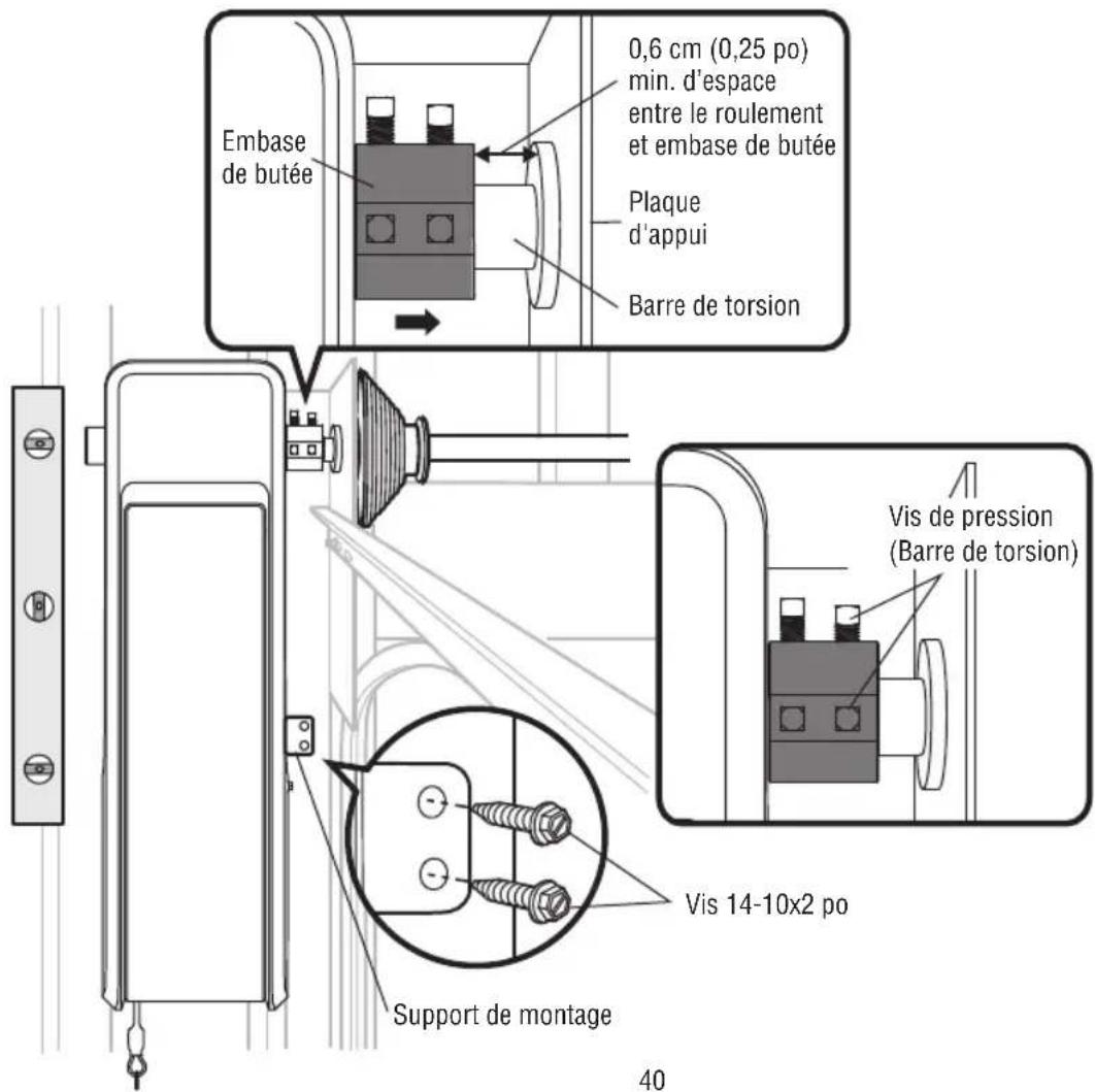
text_image
Technical diagram showing mechanical assembly steps with numbered components and directional arrows indicating motion or movement.natural_image
Silhouette of a person running with a downward arrow above (no text or symbols)Moving Door Can Cause Serious Injury or Death
Keep Clear! Door May Move at any Time Without Prior Warning
Do Not Let Children Operate the Door or Play in the Door Area
Keep Door in Sight at all Times When Door is Moving
⚠️ ⚠️ AVERTISSEMENT
text_image
Diagram showing three electrical components: a plug inserted into a socket, a wire rod with contacts, and a connector labeled BLANC GRIS.natural_image
Pure electrical circuit lines without any symbolsnatural_image
Technical line drawing of an electronic enclosure labeled LMi5, showing mounting holes and screw pins (no text or symbols beyond label)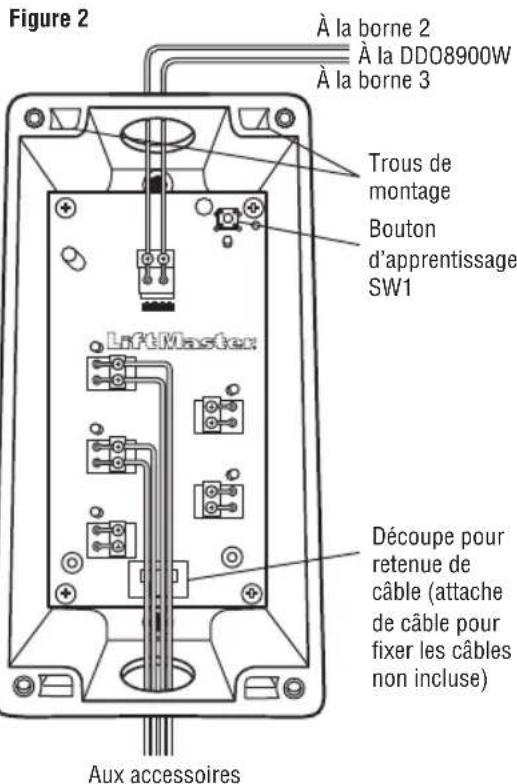
natural_image
Hand inserting a device into a control panel (no text or symbols visible)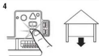
text_image
4
natural_image
Hand inserting a card into a device panel (no text or symbols visible)Ajustements
natural_image
Line drawing of a cabinet with multiple windows and a ladder, no text or symbols presentnatural_image
Technical line drawing of a multi-panel storage unit with a central box and wall-mounted base (no text or symbols)SUSPENSION TEMPORAIRE DE LA TTC
text_image
Diagram showing various electronic components with numbered labels, including a mesh device, control panel, and motor.natural_image
Pure mechanical diagram showing a spring-loaded frame with no text or symbols2850 E. Drexel Rd., Suite #180
Tucson, AZ 85706