
ZIRMM95 - Tire mounting machine Zipper - Free user manual and instructions
Find the device manual for free ZIRMM95 Zipper in PDF.
| Product type | Tire mounting machine (tire changer) |
| Brand | Zipper |
| Model | ZI-RMM95 (ZIRMM95) |
| Intended use | Mounting, demounting and inflating tires on rims of various sizes |
| Clamping unit | Clamping plate with jaws for inner/outer fixation |
| Bead breaker | Pedal operating a cylinder to separate the tire from the rim |
| Swiveling arm | With height-adjustable mounting head and mounting bar |
| Power supply | Not specified in the manual (estimate: 220-240 V, 50/60 Hz, single-phase) |
| Pneumatic supply | Compressed air required for clamping and inflation |
| Max inflation pressure | Do not exceed the pressure recommended by the tire manufacturer |
| Environmental conditions | Max humidity 70 %, temperature +5°C to +50°C (operation), -20°C to +55°C (storage) |
| Daily maintenance | Clean and lubricate the clamping plate jaws after each use |
| Monthly maintenance | Check screws, lubricate moving parts, check drive belt tension |
| Oil level | Check before each job; use SAE 30 oil |
| Cleaning | Use a mild detergent; avoid thinners, gasoline, corrosive products |
| Safety | Mandatory PPE (gloves, goggles, shoes); do not use in rain or explosive atmosphere |
| Spare parts | Use only original Zipper parts to maintain warranty |
| Warranty | 2 years for DIY use, 1 year for industrial use (from date of purchase) |
| Documents included | User manual (68 pages) available in multiple languages |
Frequently Asked Questions - ZIRMM95 Zipper
User questions about ZIRMM95 Zipper
0 question about this device. Answer the ones you know or ask your own.
Ask a new question about this device
Download the instructions for your Tire mounting machine in PDF format for free! Find your manual ZIRMM95 - Zipper and take your electronic device back in hand. On this page are published all the documents necessary for the use of your device. ZIRMM95 by Zipper.
USER MANUAL ZIRMM95 Zipper
TIRE MOUNTING MACHINE
DESMONTADA DE NEUMÁTICOS
CHANGEUR DE PNEUS
ZOUVACKA PNEUMATIK
MACCHINA SMONTAGOMME

ZI-RMM95
EAN: 9120039239101
C E

1 INHALT/ INDEX
13.1 Intended use of the machine 20
13.1.1 Technical Restrictions 20
13.1.2 Prohibited Use/Forseeable Misuse 20
13.2 User Requirements 20
13.3 General Safety Instructions 20
13.4 Electrical Safety 21
13.5 Special Safety instructions for that machine 21
13.6 Hazard warnings 22
14 TRANSPORT 22
15 ASSEMBLY 22
15.1 Preparatory Activities 22
15.1.1 Check delivery content 22
Workplace requirements 23
15.2.1 Electrical Connection 23
15.3 Compressed air connection 23
15.4 Test run 23
16 OPERATION 23
16.1 Dismount tyre from the rim 23
16.2 Mount tyre onto a rim 24
16.3 Inflate tyres 24
17 CLEANING, MAINTENANCE, STORAGE, DISPOSAL 25
17.1 Cleaning 25
17.2 Maintenance 25
Upkeep and Maintenance Plan 25
17.3 Check lubricant level 25
17.4 Check drive belt tension 25
17.5 Storage 25
17.6 Disposal 26
1.8 TROUBLESHOOTING 26
19 PREFACIO (ES) 27
20 SEGURIDAD 28
20.1 Uso adequado 28
EN CE-Conformal! - This product complies with the EC-directives.
EN Read the operation manual carefully before first use!
CRUSH HAZARD! - KEEP FEET AND OTHER BODY PARTS AWAY FROM THE
WHEEL PRESSING UNIT DURING OPERATION
IPELIGRO DE APLASTAMENTO! - MANTenga LOS PIES Y OTRAS PARTES DEL
EN CRUSH HAZARD - KEEP HANDS OFF TURNING PLATE AND MOUNTING HEAD DURING OPERATION
iPELIGRO DE APLASTAMENTO! - iMANTenga LAS MANOS APARTADAS DEL
ES PLATO DE GARRAS (AUTOCENTRANTE) Y DEL BRAZO DE MONTAJE DURANTE
LA OPERATION!
RISQUE D'ECRASEMENT! - GARDEZ LES MAINS ELOIGNEES DU PLATEAU DE
SERRAGE ET TÉTE DE MONTAGE PENDANT LE FONCTIONNEMENT!
NEBEZPECI ROZDRCENI! - BEHEM PROVOZU DRZE RUCE Z DOSAHU OTOCNÉHO TALIRE A
C2 MONTAZNI HLAVY!!
PERICOLO DI SCHIACCIAMENTO! - TENERE LE MANI LONTANE DAL TAVOLO ROTANTE E DALLA
TESTA DI MONTAGGIO DURANTE L'USO!
CRUSH HAZARD - KEEP HANDS AND OTHER BODY PARTS OFF CLAMPING CYLINDERS DURING
OPERATION
iPELIGRO DE APLASTAMENTO! - MANTenga LAS MANOS Y OTRAS PARTES
ES DEL CUERPO APARTADAS DE LOS CILINDROS DE SUJEccion DURANTE LA
OPERACION!
RISQUE D'ÉCRASEMENT! - GARDEZ LES MAINS ET LES AUTRES PARTIES DU
FR CORPS ELOIGNEEES DES CYLINDRES DE SERRAGE PENDANT LE
FONCTIONNEMENT
NEBEZPECI ROZDRCENI! - BEHEM PROVOZU DRZTE RUCE A OSTATNI CASTI TELA MIMO
DOSAH UPÍNACÍHO VÁLCE!
PERICOLO DI SCHIACCIAMENTO! - TENERE LE MANI E LE ALTRE PARTI DEL CORPO LONTANE
11 DAI CILINDRI DI SERRAGGIO DURANTE L'USO!

DE QUETSCHUNGSGEFAHR! - HANDE UND ANDERE KORPERTEILE WAHREND DEM BETRIEB NIE ZWISCHEN KLEMMBACKEN UND REIFEN HALTEN!
EN CRUSH HAZARD - KEEP HANDS AND OTHER BODY PARTS OFF CLAMPING SHOES AND TYRE!
ES IPELIGRO DE APLASTAMIENTO! - MANTenga LAS MANOS Y OTRAS PARTES DEL CUERPO APARTADAS DE LAS MORDAZAS Y DE LA RUEDA!
FR RISQUE D'ECRASEMENT! - GARDEZ LES MAINS ET LES AUTRES PARTIES DU CORPS ELOIGNÉES DES MORS ET ROUE!
CZ NEBEZPECI ROZDRCENI-BEHEM PROVOZU NEVKLADEJTE RUCE ANI OSTATNI CASTI TELA MEZI UPINACI CELISTI A PNEUMATIKU!
IT PERICOLO DI SCHIACCIAMENTO! - TENERE LE MANI E LE ALTRE PARTI DEL CORPO LONTANE DALLE GANASCE E DAGLI PNEUMATICI DURANTE L'USO!
DE Personliche Schutzausrüstung/TRagen!
EN Wear personal protective equipment!
ES iUsar equipo de proteccion!
FR Porter équipement de protection individuelle!
CZ Pouzivejte ochranné prostředky!
IT Indossare equipaggiamento protettivo!
3 ILLUSTRATIONEN
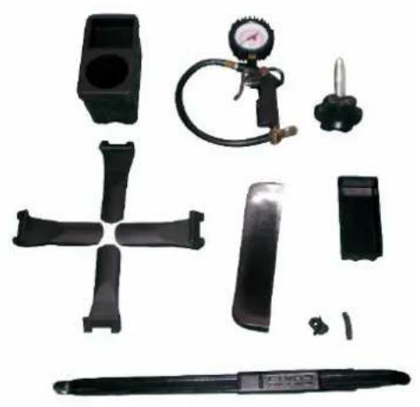
Abb. B
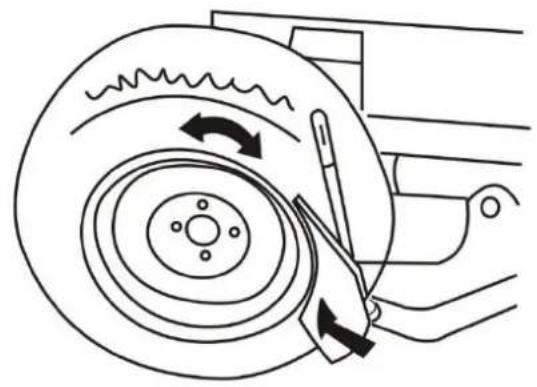
Abb. C
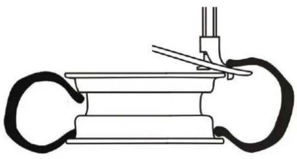
Abb. D

Abb. E
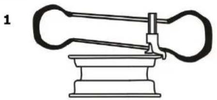
Abb. F

Abb. G
1
2
2
4 TECHNIK / TECHNIC
4.1 Komponenten / components / elementos / constituents / soucasti / Componenti
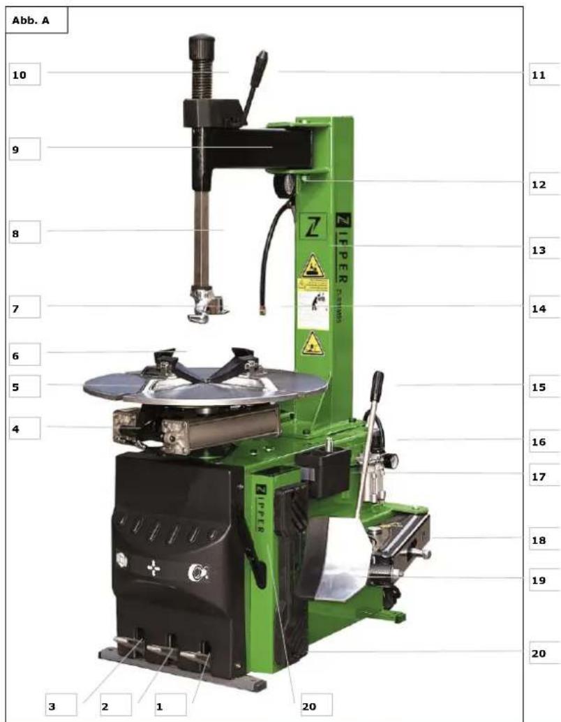
| 1 | Bedienpedal zur Steuerung des Abdrückers Foot pedal for bed-breaking Pedal de control para controlar el destalonador Pédale de contrôle de détilonneur Ovladaci pedal uvolnēi patky plasté Pedale di lavoro per ilCONTROL del meccanismo di rilascio | 12 | Manometer / Pressure control / Manómetro / Manometre / Tlakoměr / Manometro |
| 2 | Bedienpedal zur Steuerung der Klemmbacken Foot pedal for type clamping Pedal de operación para el control de las mor-dazas de sujeción Pédale de contrôle des mors de serrage Ovladaci pedal upinacích celisti Pedale di lavoro per ilCONTROL delle ganasse | 13 | Säule / column / Columna / Colonne / Sloupek / Colonna |
| 3 | Bedienpedal zur Steuerung des Drehtellers Foot pedal for tyre disc rotation Pedal de operación para controlar el Plato de garras Pédale de contrôle du plateau de serrage Ovladaci pedal otočného taliře Pedale di lavoro per ilCONTROL del ravolo rotante | 14 | Befüllschlauch / air hose / Manguera de lienado / Flexible d'air / Hadice hušťeni / Tubo di riempimento |
| 4 | Klemmzylinder / Clamping cylinders Cilindros de sujeción / Vérins de serrage Upínaci vázec / Cilindri di serraggio | 15 | Abdruckerhebel / Bed-breaking lever / Palanca del destalonador /Levier de détilonneur / Páka odtrăčeni patky plastiţe / Leva meccanismo di rilascio |
| 5 | Drehsteller / Tyre disc / Plato de garras (autocentrante) /Plateau de serrage Otočné taliř / Tavolo rotante | 16 | Druckluftanschluss / Compressed air connection / Conexión de aire comprimido /Raccord d'air comprimé / Prípojen tlakového vžduchu / Attacco aria compressa |
| 6 | Klemmbacken / Clamping jaws / Mordazas / Mors / Upinaci Čelisti / Ganasce | 17 | Schmierfettbehälter / Grease container / Depósito de aceite /Réservoir d'huile / Nádržka mazání / Contenitore grasso lubrificante |
| 7 | Montagekopf / Mounting head / Cabezal de montaje / Tête de montage / Montážní hlava / Testa di montaggio | 18 | Abdrückerarm / Bead-breaking arm / Brazo del destalonador / Bras de détaillonneur / Rameno odlacovace patky plástě / Braccio meccanismo di rilascio |
| 8 | Montagestange / Mounting bar / Barra de montaje / Barre de montage / Montážní páka/ Barra di montaggio | 19 | Abdrücker / Bed-breaker / Destalonador /Détaillonneur / Čepel uvolnovace patky plástě / Meccanismo di rilascio |
| 9 | Schwenkarm / Swing arm / Brazo basculante /Bras pivotant / Náklopná ruka / Braccio girevole | 20 | Reifenanlegeschiene / Tyre positioning plate / Plato de posicionamento de neumático / Plaque de positrènment du pneu / Páka naložéní kola / Guida di alimentazione pneumatico |
| 10 | Rückstellfederung / Retaining spring / Muelle de retencion / Ressort de retenue / Prúžina uvolnovác patky/ Molla di richiamo | 21 | Montierhebel / Mounting lever / Palanca de montaje /Levier de montage / Montážní páka / Leva di montaggio |
| 11 | Höhenarretierhebel / Height fixation lever / Palanca de bloqueo de alteura /Levier de verrouillage d'hauteur / Páka yškové aretace / Leva di arresto in altozza |
4.2 Technische Daten / Technical date /Ficha的技术ica / Fiche technique /Technická data /dati technici
| Motorleistung / motor power /Potencia del motor /Puissance de moteur /Výkon motoru / Potenza motore | 1,1kW |
| Spannung / voltage / voltaje/ Voltage /Napájecí napěti / Tensione di assorbimento | 230V /1 / 50Hz |
| Anforderung an Drucklautanschluss / Required Compressed air /Toma de aire comprimido /Air comprimé /Prívod stlačeného vzduchu / Attacco aria compressa | 8-10bar1/4" |
| Abdrückkraft / Bed-breaking force /Potencia destalonador / Force du détalonneur /Odtlačovaci sila / Forza di pressione | 2500kg |
| Felgendurchmesser / Rim diameter /Diámetro de la llanta / Diamètre de la jante /Prümér rákku / Diametro cerchio | 10-22" |
| Felgenbreite / Rim width /Ancho de llanta /Largeur de la jante /Sírfka rákku / Largezza cerchio | 3-12" |
| Reifendurchmesser max. / Tyre diameter max. /Diámetro maxi. de rueda / Diamètre maxi de roue /Max. prümér pneumatiky / Diametro max. pneumatico | 960mm |
| Reifenbreite max. / Tyre width max. /Ancho maxi. de rueda / Largeur maxi de roue /Max. sírfka pneumatiky / Larghezza max. pneumatico | 330mm |
| Max. Drehmoment Drehtrüller / max. torque of tyre disc /Máx. torque del plato de garra /Max. couple of serrage de plateau /Max. točivý moment otočného talíře / Coppia max. ravolo rotante | 110kgm |
| Schalldruckpegel LpA / sound pressure level LpA Nivel presión acústica LpA/Niveau sonorezaručena hladina akustického výkonu LpA/Livello di rumorosità LpA | <70dB(A) |
| Gewicht netto/ weight net / Peso neto / poids net /Hmotnost netto / Peso neto | 180kg |
| Verpackungs-Abmessungen / parchaging dimensions / Dimensiones delembalaje / Dimensions de l'emballage / Rozmery balenia | 980x760x850mm |
| Maschinenmaße / machine dimensions / dimensiones de la máquina /dimensions des machines / Rozměry stroje | 950x800x1800mm |
5 VORWORT (DE)
This manual contains information and important instructions for the installation and correct use of the ZIPPER "Tire mounting machine" ZI-RMM95.
Following the usual commercial name of the machine (see cover) is substituted in this manual with the name "machine".

This manual is part of the product and shall not be stored separately from the product. Save it for later reference and if you let other people use the product, add this instruction manual to the product.
Please read and obey the security instructions!
Due to constant advancements in product design, construction pictures and content may diverse slightly. However, if you discover any errors, inform us please.
Technical specifications are subject to changes!
Please check the product contents immediately after receipt for any eventual transport damage or missing parts.
Claims from transport damage or missing parts must be placed immediately after initial product receipt and unpacking before putting the product into operation.
Please understand that later claims cannot be accepted anymore.
Copyright
2018
This document is protected by international copyright law. Any unauthorized duplication, translation or use of pictures, illustrations or text of this manual will be pursued by law. Court of jurisdiction is the regional court Linz or the competent court for 4707 Schlüsslberg, Austria!
Customer service contact
This section contains information and important notices for safe commissioning and handling of machine.

For your own safety, read these operating instructions carefully before putting the machine into operation. This will enable you to handle the machine safely and prevent misunderstandings as well as possible damage to property and persons. Also observe the symbols and pictograms used as well as the safety instructions and hazard warnings!
13.1 Intended use of the machine
The machine is intended exclusively for the following activities: Mounting and dismounting tyres on rims and inflating these tyres.
ZIPPER-MASCHINEN assumes no responsibility or warranty for any other use or use beyond this and for any resulting damage to property or injury.
13.1.1 Technical Restrictions
The machine is intended for use under the following ambient conditions:
Relative humidity: max. 70%
Temperature (for operation) +5^ C bis +50^ C
Temperature (for storage and/or transport) -20^ bis +55^
13.1.2 Prohibited Use / Forseeable Misuse
Operation of the machine without adequate physical and mental aptitude
- Operating the machine without appropriate knowledge of the operating instructions (machine + motor).
Changes in the design of the machine
- Operating the machine in wet and rainy conditions
- Operating the machine in a potentially explosive environment
- Remove the safety markings attached to the machine.
- Modify, circumvent or disable the safety devices of the machine.
- Use of the machine for the transport of persons
The prohibited/hazardous use or disregard of the information and instructions presented in this manual will result in the voiding of all warranty and damage claims against Zipper Maschinen GmbH.
13.2 User Requirements
The physical and mental suitability as well as knowledge and understanding of the operating instructions are prerequisites for operating the machine. Persons who, because of their physical, sensory or mental abilities or their inexperience or ignorance, are unable to operate the machinery safely must not use it without the supervision or instruction by a responsible person. Please note that local laws and regulations may determine the minimum age of the operator and restrict the use of this machine!
Put on your personal protective equipment before working on the machine.
Work on electrical components or equipment may only be carried out by a qualified electrician or carried out under the guidance and supervision of a qualified Electrician.
13.3 General Safety Instructions
To avoid malfunctions, damage and health hazards when working with the machine, the following points must be observed in addition to the general rules for safe working:
-
Before each start-up, check the machine for completeness and function.
-
Choose a level, vibration-free, non-slip surface for the installation location.
- Ensure sufficient space around the machine!
- Ensure sufficient lighting conditions at the workplace to avoid stroboscopic effects!
- Only use perfect tools that are free of cracks and other defects (e.g. deformations).
- Remove setting tools from the machine before switching on.
- Keep the area around the machine free of obstacles (e.g. dust, chips, cut workpiece parts etc.).
- Check the strength of the machine connections before each use.
- Never leave the running machine unattended. If necessary, stop the machine before leaving.
- The machine may only be operated, serviced or repaired by persons who are familiar with it and who have been informed of the dangers arising in the course of this work.
- Ensure that unauthorised persons maintain an appropriate safety distance from the machine and keep children away from the machine in particular.
- Wear suitable protective equipment (ear protection, gloves when handling tools) as well as close-fitting work protective clothing - never wear loose clothing, ties, jewellery etc. - danger of being drawn in!
- Hide long hair under hair protection.
Always work with care and the necessary caution and never use excessive force. - Do not overload the machine!
- Do not work on the machine if it is tired, not concentrated or under the influence of medication, alcohol or drugs!
- Do not use the machine in areas where vapours from paints, solvents or flammable liquids represent a potential danger (danger of fire or explosion!).
- Make sure that the ON/OFF switch is in the "OFF" position before connecting the machine to the power source.
- Do not use the power tool if it cannot be switched on and off with the ON/OFF switch.
- Ensure that the unit is earthed.
- Only use suitable extension cords.
- Always shut down the machine before carrying out any conversion, adjustment, measuring, cleaning, maintenance or repair work and always disconnect it from the power supply for maintenance or repair work. Before starting any work on the machine, wait until all tools or machine parts have come to a complete standstill and secure the machine against unintentional restarting
13.4 Electrical Safety
- Proper plugs and matching sockets reduce the risk of electric shock. The plug of the power tool must be adapted to the socket. Never modify the plug in any way. Do not use adapter plugs with earthed power tools.
- There is an increased risk of electric shock if your body is in ground contact. Avoid physical contact with earthed objects, such as pipes, radiators, etc.
Water that penetrates power tools increases the risk of electric shock. Do not expose the power tools to rain or moisture. - A damaged or tangled cable increases the risk of electric shock. Handle the cable with care. Never use the cable to carry, pull or disconnect the power tool. Keep the cable away from heat, oil, sharp edges or moving parts.
If you are using an outdoor power tool, use an extension cord suitable for outdoor use! - Use of the power tool in a humid environment is only permitted if the power source is protected by a residual current circuit breaker.
- Do not use the power tool if it cannot be switched on and off with the ON-OFF switch.
13.5 Special Safety instructions for that machine
- Keep away from the machine when operating any of the foot pedals! Take especially care to keep hands off the tyre plate area and keep the feet off the bed-breaking device
- Never exceed the recommended max. tyre pressure of the tyre manufacturer.
Always check tyre, rim and tyre position on rim before and during inflating process.
13.6 Hazard warnings
Despite intended use, certain residual risks remain. Due to the design and construction of the machine, hazardous situations may occur which are identified as follows in these operating instructions:
| DANGER | |
| ! | A safety instruction designed in this way indicates an imminently hazardous situation which, if not avoided, will result in death or serious injury. |
| WARNING | |
| ! | Such a safety instruction indicates a potentially hazardous situation which, if not avoided, may result in serious injury or even death. |
| CAUTION | |
| ! | A safety instruction designed in this way indicates a potentially hazardous situation which, if not avoided, may result in minor or moderate injury. |
| NOTICE | |
| ! | A safety note designed in this way indicates a potentially dangerous situation which, if not avoided, may result in property damage. |
Irrespective of all safety regulations, their sound common sense and corresponding technical suitability/training are and remain the most important safety factor in the error-free operation of the machine. Safe working depends first and foremost on you!
14 TRANSPORT
| WAR NI NG | |
| Damaged or insufficiently strong hoists can result in serious injury or even death. Always check hoists for adequate load-bearing capacity and perfect condition, secure loads carefully and never stand under suspended loads. | |
To ensure proper transport, also observe the instructions and information on the transport packaging regarding centre of gravity, attachment points, weight, means of transport to be used and the prescribed transport position, etc.
The tire mounting machine must be moved in its original packaging to the place of operation. The packed machine can be moved with a fork truck or a manual fork lift.
The machine is heavy. At least two persons are required for transport and installation.
15 ASSEMBLY
15.1 Preparatory Activities
15.1.1 Check delivery content
Check the machine immediately after delivery for transport damage and missing parts.
15.2 Workplace requirements
Choose a suitable site for the operation. It must fulfill the regulations for workplace safety applicable in your country and must provide a suitable electronic supply connection and pressure air connection with 8-10bar.
The ground must be level and solid and capable to bear the machines weight.
Take care to position the machine so that it has at least 1m of free space around.
Fix the machine through the 4 bores in the machine base to the ground!
15.2.1 Electrical Connection
WARNING
Dangerous electrical voltage! The machine may only be connected to the mains supply and the associated checks carried out by a qualified electrician or under the instruction and supervision of a qualified electrician!
The connection of the machine to the electric power supply and the following checks are to be carried out by respectively certified electricians only!
The electronic connection of the machine is designated for operation with a grounded power socket!
The connector plug may not be altered or manipulated!
A damaged cable has to be replaced immediately!
The supply net must be secured with at least 16A.
Check, whether the supply net voltage and frequency complies with the machine motors requirements!
15.3 Compressed air connection
Connect the machine to compressed air supply at the compressed air connection (16). ATTENTION: The ZI-RMM95 may be only operated with pressure levels between 8-10 Bar.
15.4 Test run
Check the function of the foot pedals and of the pressure air hose.
If you notice any malfunctions check all connections again
16 OPERATION
CAUTION

In order to avoid damages, use the provided mounting lever to initiate the demounting and mounting of tyres.
The connecting area between tyre and rimbed, where the bed-breaker separates the tyre from the rim, should always be lubricated with suitable lubricants to prevent the rim from damage.
Check for eventual prescribed running directions for tyre mounting of the tyre wall. Tyres and rims must match together regarding their technical dimensions.
Always check the tyre extensively for any abnormalities like deformation, surface damage, excessive or uneven wear etc.
before mounting it.
Always check whether tyre/rim requires special mounting procedures. For this inform yourself in documentations etc. oft he respective manufacturer.
When inflating tyres, check tyre pressure and tyre form frequently.
16.1 Dismount tyre from the rim
Slowly release the air from the tyre.
Remove all balance weights and other foreign materials from the rim.
Lubricate the tyre bead with suitable lubricant or soap suds, before you separate the tyre from the rim with the bead-breaker to prevent the tyre bead from damage.
-
Place the tyre to the tyre positioning plate (20), so that the bead-breaker (19) edge is max. 1cm far from the rim edge.
-
Keep hands/feet of danger area of bead-breaker!
- Operate foot pedal (1), the bead-breaker will press the tyre off the rim.
- Remove these steps several times until the tyre is separated from the rim entirely.
- Place the tyre onto the tyre disc (5). ATTENTION: for asymmetric lowbed-rims place the rims so that the flat side shows upwards.
- Operate foot pedal (2) for clamping and centering the rim.
- Attention: For sensible rims use the four provided plastic clamps.
- If you wish to clamp your rim from inside to outside, first operate pedal (2) until jaws are centered in the middle, place the rim onto the tyre disc and operate the pedal (2) again.
- Swing the swing arm (9) into working position over the rim edge, press the mounting bar downwards until the mounting head (7) clears the rim edge 1-2mm
Fix the head in this position with the height fixation lever (11) and fix the swing arm position as well.
See figure D:
- Slip the outer tyre bead with the help of the provided mounting bar over the mounting head (7).
- Operate the foot pedal (3) to move the tyre disc (5) until the outer tyre bead is slipped over the rim edge entirely. Always check the position of the valve during rotation to avoid damage!
See figure E:
- Remove the air tube first, if present.
- Slip with the mounting lever the lower tyre bead over the mounting head.
- Operate the foot lever (3) to pull the entire lower tyre bead over the rim edge
16.2 Mount tyre onto a rim
- Check whether tyre and rim match regarding technical dimensions, especially width and diameter!
If using a new rim, clamp it as described, if you mount a new tyre on a already clamped rim - let it be clamped. - Lubricate the tyre bead with suitable lubricant!
See Figure F:
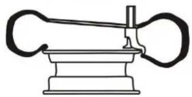
- Place the tyre onto the rim in a way, that the left side is higher than the right side and bring the mounting head into position as shown in the figure.
- Position the tyre in a way that the tyre bead is over the left (see Fig. F 1) but is simultaneously under the right side (see Fig. F 2) of the mounting head.
- Operate foot pedal (1), the inner tyre bead gets pulled under the rim edge.
If required, insert now the tyre-tube in a way that it will not constrain the mounting.
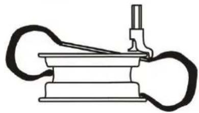
See Figure G:
Perform the mounting similarly.
But when having the last 10-15cm being pulled under the rim edge take special care that the tyre bead gets not damaged. Stop the tyre disc if required and reverse if necessary. Try to easy the pull down by pressing onto the tyre on the other side already being pulled under the rim.
16.3 Inflate tyres
WARNING
Always check whether tyre and rim match together in all technical aspects.
Check extensively, whether there is any damage or abnormality of the tyre or rim and check whether the tyre is really mounted onto the rim correctly.
NEVER exceed the max. tyre pressure recommended by the tyre manufacturer.
When inflating air into the tyre, check the pressure frequently, check regularly the tyre shape.
During the air inflating process itself keep yourself away from the tyre as much as possible.
In order to inflate a tyre connect the provided inflating device to the air hose (14).
Connect the inflating device to the tyre valve. Through pressing the lever of the inflating device air gets inflated into the tyre.
17 CLEANING, MAINTENANCE, STORAGE, DISPOSAL
17.1 Cleaning
NOTICE

Wrong cleaning agents can attack the varnish of the machine. Do not use solvents, nitro thinners, or other cleaning agents that could damage the machine's paint. Observe the information and instructions of the cleaning agent manufacturer!
Prepare the surfaces and lubricate the bare machine parts with an acid-free lubricating oil.
17.2 Maintenance
WARNING

Danger from electric voltage and compressed air! Manipulation of the machine with the power supply or compressed air supply upright can lead to serious injuries or death. Always disconnect the machine from the power supply and compressed air supply before carrying out any maintenance work.
The machine is low-maintenance and only a few parts have to be serviced. Nevertheless, malfunctions or defects which could impair the safety of the user must be rectified immediately!
IMPORTANT:deaerate the machine at least every 3 months completely!
Inspection and Maintenance Plan
| Upkeep and Maintenance Plan | |
| Clean tyre disc and lubricate clamping jaw joints. | Clean tyre disc and lubricate clamping jaw joints. |
| Lubricate Swing arm (9), mounting bar (8) and all other moving parts and joints | Lubricate Swing arm (9), mounting bar (8) and all other moving parts and joints |
| Check and tighten all screw fittings if necessary. | Check and tighten all screw fittings if necessary. |
| Check drive belt tension | Check drive belt tension |
| Deaerate entire hydraulic system completely | Deaerate entire hydraulic system completely |
17.3 Check lubricant level
Check the lubricant level in the lubricant container (17). Add SAE 30 oil if necessary.
17.4 Check drive belt tension
Remove the cover on the left side of the tyre changing machine to gain access to the drive belts. For this unscrew the four fixing screws of the cover and remove it.
If the belt is not tightened sufficiently or is dirty or polluted with lubricants, it might slip on the pulleys and cause stalling. In order to tighten the belt, please adjust it with a bolt being positioned on the motor plate.
17.5 Storage
HI NWEIS

Improper storage can damage and destroy important components. Only store packed or unpacked parts under the intended ambient conditions!
In case of a longer interruption of operation or shutdown, clean the machine and then store it out of the reach of children in a dry place protected from frost and other weather influences!
Disconnect the machine from the power supply and the air compression supply.
Release the tension of the hydraulic system before disconnecting it (16) from the compressed air supply.
17.6 Disposal
Observe the national waste disposal regulations. Never dispose of the machine, machine components or equipment in residual waste. If necessary, contact your local authorities for information on the disposal options available.
If you buy a new machine or an equivalent device from your specialist dealer, he is obliged in certain countries to dispose of your old machine properly.
18 TROUBLESHOOTING
WARNING

Danger from electric voltage and compressed air! Manipulation of the machine with the power supply or compressed air supply upright can lead to serious injuries or death. Always disconnect the machine from the power supply and compressed air supply before carrying out any troubleshooting work.
Many possible sources of error can be excluded in advance if the machine is properly connected to the mains.
If you are unable to carry out necessary repairs properly and/or do not have the required training, always consult a specialist to correct/solve the problem!
| Failure | Possible cause / solution |
| Tyre disc turns in one direction only | Problem: commutator broken solution: let commutator be replaced |
| Tyre disc does not rotate at all | Problem: defect belt Solution: replace belt Problem: belt not tensioned Solution: tension the belt Problem: commutator broken solution: let commutator be replaced Problem: motor defect Lösung: let this possibility be checked by a certified electrician who should check the power supply, the cables and the motor to localize the error exactly. |
| Tyre disc stalls during rotation | Problem: belt slips Solution: clean + tension belt |
| Clamping jaws open/close too slowly | Problem: pressure air silencer in the machine Solution: Through belt access door you gain access to silencers as well, clean them! Release pressure from hydraulic system beforehand! |
| Jaws do not clamp rim sufficiently | Problem: insufficient compression rate supply Solution: check compression air supply pressure Problem: jaws defect Solution: replace jaws Problem: pressure air silencer in the machine Solution: Through belt access door you gain access to silencers as well, clean them! Release pressure from hydraulic system beforehand! Problem: clamping cylinder defect Solution: replace cylinders |
19 PREFACIO (ES)
(EN) With ZIPPER spare parts you use spare parts that are ideally matched to each other. The fitting accuracy of the parts shortens their installation time and increases the service life of the machine.
NO TE
The installation of parts other than original spare parts leads to the loss of the
guarantee! Therefore, when replacing components/parts, only use original spare parts! When ordering spare parts, please use the service form at the end of this manual. Always state machine type, spare part number and designation. In order to avoid misunderstandings, we recommend enclosing a copy of the spare part drawing with the spare part order, on which the required spare parts are clearly marked.
You will find the ordering address under customer service addresses in the foreword to this documentation.
Company ZIPPER Maschinen GmbH grants for mechanical and electrical components a warranty period of 2 years for amateur use; and warranty period of 1 year for professional use, starting with the purchase of the final consumer. In case of defects during this period, which are not excluded by paragraph 3, ZIPPER will repair or replace the machine at its own discretion.
2.) Report:
In order to check the legitimacy of warranty claims, the final consumer must contact his dealer. The dealer has to report in written form the occurred defect to ZIPPER. If the warranty claim is legitimate, ZIPPER will pick up the defective machine from the dealer. Returned shipments by dealers which have not been coordinated with ZIPPER, will not be accepted and refused.
3.) Regulations:
a) Warranty claims will only be accepted, when a copy of the original invoice or cash voucher from the trading partner of ZIPPER is enclosed to the machine. The warranty claim expires if the accessories belonging to the machine are missing.
b) The warranty does not include free checking, maintenance, inspection or service works on the machine. Defects due to incorrect usage of the final consumer or his dealer will not be accepted as warranty claims either. Some examples: usage of wrong fuel, frost damages in water tanks, leaving fuel in the tank during the winter, etc.
c) Defects on wear parts are excluded, e.g. carbon brushes, collection bags, knives, cylinders, cutting blades, clutches, sealings, wheels, saw blades, splitting crosses, riving knives, riving knife extensions, hydraulic oils, oil/air/fuel filters, chains, spark plugs, sliding blocks, etc.
d) Also excluded are damages on the machine caused by incorrect or inappropriate usage, if it was used for a purpose which the machine is not supposed to, ignoring the user manual, force majeure, repairs or technical manipulations by not authorized workshops or by the customer himself, usage of non-original ZIPPER spare parts or accessories.
e) After inspection by our qualified personnel, resulted costs (like freight charges) and expenses for not legitimated warranty claims will be charged to the final customer or dealer.
f) In case of defective machines outside the warranty period, we will only repair after advance payment or dealer's invoice according to the cost estimate (incl. freight costs) of ZIPPER.
g) Warranty claims can only be granted for customers of an authorized ZIPPER dealer who directly purchased the machine from ZIPPER. These claims are not transferable in case of multiple sales of the machine.
4.) Claims for compensation and other liabilities:
The liability of company ZIPPER is limited to the value of goods in all cases. Claims for compensation because of poor performance, lacks, damages or loss of earnings due to defects during the warranty period will not be accepted. ZIPPER insists on its right to subsequent improvement of the machine.
52 GARANTÍA Y SERVICIO (ES)
1.) Garantía:
We monitor the quality of our delivered products in the frame of a Quality Management policy.
Your opinion is essential for further product development and product choice. Please let us know about your:
- Impressions and suggestions for improvement.
- experiences that may be useful for other users and for product design
- Experiences with malfunctions that occur in specific operation modes
We would like to ask you to note down your experiences and observations and send them to us via FAX, E-Mail or by post
Please describe amongst others in the problem: What has cause the problem/defect, what was the last activity before you noticed the problem/defect? For electrical problems: Have you had checked you electric supply and the machine already by a certified electrician?
- Bitebeachten
Additional information
INCOMPLETELY FILLED SERVICE FORMS CANNOT BE PROCESSED! FOR GUARANTEE CLAIMS PLEASE ADD A COPY OF YOUR ORIGINAL SALES/ DELIVERY RECEIPT OTHERWISE IT CANNOT BE ACCEPTED. FOR SPARE PART ORDERS PLEASE ADD TO THIS SERVICE FORM A COPY OF THE RESPECTIVE EXPLODED DRAWING WITH THE REQUIRED SPARE PARTS BEING MARKED CLEARLY AND UNMISTAKABLE. THIS HELPS US TO IDENTIFY THE REQUIRED SPARE PARTS FASTLY AND ACCELERATES THE HANDLING OF YOUR INQUIRY.


- INHALT/ INDEX
- TRANSPORT 22
- ASSEMBLY 22
- OPERATION 23
- CLEANING, MAINTENANCE, STORAGE, DISPOSAL 25
- ILLUSTRATIONEN
- TECHNIK / TECHNIC
- Komponenten / components / elementos / constituents / soucasti / Componenti
- Technische Daten / Technical date /Ficha的技术ica / Fiche technique /Technická data /dati technici
- VORWORT (DE)
- Please read and obey the security instructions!
- Copyright
- Customer service contact
- Intended use of the machine
- ZIPPER-MASCHINEN assumes no responsibility or warranty for any other use or use beyond this and for any resulting damage to property or injury.
- Technical Restrictions
- Prohibited Use / Forseeable Misuse
- User Requirements
- General Safety Instructions
- Electrical Safety
- Special Safety instructions for that machine
- Hazard warnings
- TRANSPORT
- ASSEMBLY
- Preparatory Activities
- Check delivery content
- Workplace requirements
- Electrical Connection
- WARNING
- Compressed air connection
- Test run
- OPERATION
- CAUTION
- Dismount tyre from the rim
- Mount tyre onto a rim
- Inflate tyres
- CLEANING, MAINTENANCE, STORAGE, DISPOSAL
- Cleaning
- NOTICE
- Maintenance
- Check lubricant level
- Check drive belt tension
- Storage
- HI NWEIS
- Disposal
- TROUBLESHOOTING
- PREFACIO (ES)
- NO TE
- The installation of parts other than original spare parts leads to the loss of the
- 2.) Report:
- 3.) Regulations:
- 4.) Claims for compensation and other liabilities:
- GARANTÍA Y SERVICIO (ES)
- 1.) Garantía:
Brand : Zipper
Model : ZIRMM95
Category : Tire mounting machine