
VAPZ - Ventilation Soler & Palau - Free user manual and instructions
Find the device manual for free VAPZ Soler & Palau in PDF.
| Product Type | Single-phase fan speed controller |
| Brand | Soler & Palau |
| Model | VAPZ (VAPZ-3, VAPZ-5, VAPZ-11) |
| Power supply | Single-phase 220-240 V ~, 50 Hz |
| Max. motor current | 3 A (VAPZ-3), 5 A (VAPZ-5), 11 A (VAPZ-11) |
| Fuse | 5x20 mm 4 A type F (VAPZ-3), 5x20 mm 6.3 A type F (VAPZ-5), 6.3x32 mm 12.5 A type F (VAPZ-11) |
| Power dissipation | To be evacuated with sufficient clearance |
| Motor output | Variable voltage from Smin (90-230 V) to Smax (up to supply voltage) |
| Analog input IN | 0-20 mA (S1.1 ON) or 0-10 Vdc (S1.1 OFF), adjustable Emin/Emax |
| Run/stop input | Dry contact (open = stop, closed = run) |
| Maximum speed input | Dry contact (closed = output at Smax) |
| SELV 24 Vdc output | 100 mA continuous, 200 mA peak (1 s max / 30 s) |
| Gas valve relay output | Potential-free contact, 250 V~ / 10 A (cos φ=0.6) or 16 A (cos φ=1) |
| Front panel indicator | Green: motor running (output > 0 V) |
| Enclosure | Protection rating IP55, material ABS V0, color RAL 7035 |
| Cable glands supplied | 2x Pg7 + 2x Pg11 |
| Operating temperature | -10 °C to +50 °C |
| Operating humidity | 30 % to 95 % RH |
| Storage temperature | -20 °C to +60 °C |
| Conductor cross-section | 1 to 2.5 mm² (flexible with ferrule or rigid) |
| Insulation class | 1 |
| Maintenance | Periodically check tightening of connections and ambient temperature |
| Standards | CE, NF C 15-100 |
Frequently Asked Questions - VAPZ Soler & Palau
User questions about VAPZ Soler & Palau
0 question about this device. Answer the ones you know or ask your own.
Ask a new question about this device
Download the instructions for your Ventilation in PDF format for free! Find your manual VAPZ - Soler & Palau and take your electronic device back in hand. On this page are published all the documents necessary for the use of your device. VAPZ by Soler & Palau.
USER MANUAL VAPZ Soler & Palau
Emin < Emax ≤ 10V DC
Si senal coriente: 0mA≤ Emin < 20mA
Emin < Emax ≤ 20 mA
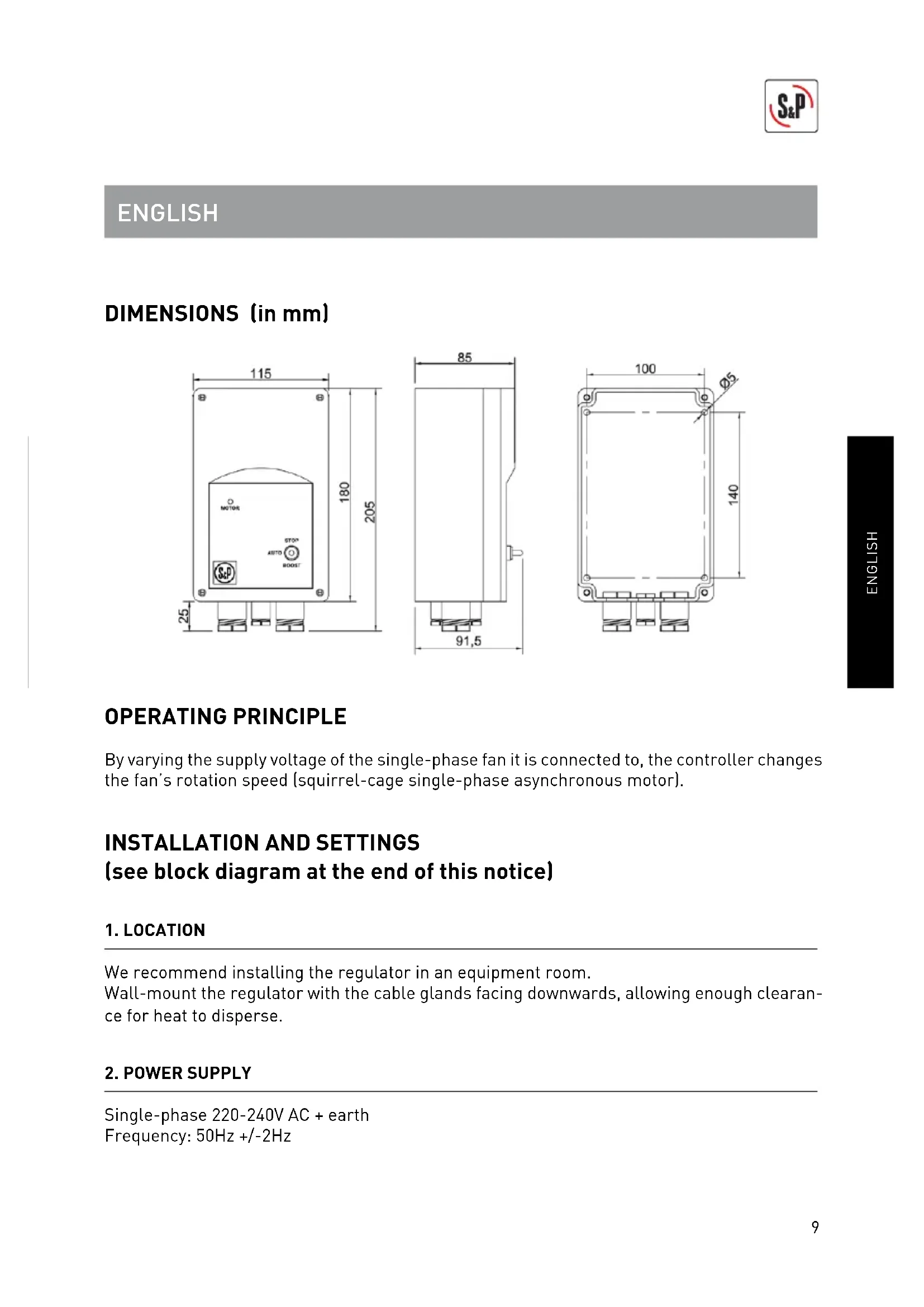
By varying the supply voltage of the single-phase fan it is connected to, the controller changes the fan's rotation speed (squirrel-cage single-phase asynchronous motor).
INSTALLATION AND SETTINGS (see block diagram at the end of this notice)
1. LOCATION
We recommend installing the regulator in an equipment room. Wall-mount the regulator with the cable glands facing downwards, allowing enough clearance for heat to disperse.
2. POWER SUPPLY
Single-phase 220-240V AC + earth Frequency: 50Hz + / - 2Hz
3. CONTROL PANEL
- "OFF" => motor output = 0V on condition that max. speed input is not activated
- "AUTO" => motor output depends on the status of the inputs
- "ON" => motor output = max. voltage (in accordance with Smax setting).
4. INPUT GO/STOP
Condition = panel switch set to auto:
- circuit open between the 2 terminals => stop
- circuit closed => on (motor output depends on IN analogic input status)
At powerup, motor output is forced to max. value for 8s to set the motor running.
5. INPUT MAX. SPEED
Always takes priority regardless of the position of the panel switch and the status of the go/stop and IN inputs:
- Circuit open between the 2 terminals => input inactive (motor output depends on analogic input).
- Circuit closed motor output = max. voltage (in accordance with Smax setting).
6. PROPORTIONAL MODE (VAV): ANALOGIC INPUT IN
Condition = front panel switch set to AUTO, "ON/OFF" input set to ON and "Max. speed" input inactive.
Changes in motor output depend on this input:
Motor output [V AC]

2 types of signal possible for analogic input:
- current signal 4-20 mA if switch S1.1 set to ON (factory setting)
- voltage signal 0-10V DC if switch S1.1 set to OFF
Emin and Emax settings:
Factory settings: Emin = 7.2 mA; Emax = 14.4 mA
These settings are for connecting a C02 sensor.
- Range of possible settings:
If signal voltage: 0V≤ Emin < 10VDC
Emin < Emax ≤ 10V DC
If signal current: 0mA≤ Emin < 20mA
Emin < Emax ≤ 20 mA
To change the factory settings:
Example "Emin":
- Connect a voltmeter (DC voltage) between GND and Emin.
-Factory setting = 2.12V - Using a fl at-headed screwdriver, rotate the trimmer marked " Emin" (e.g. until the voltmeter indicates 2V).
- The value matches Emin/4 if analog input = current.
(Example = a reading of 2V means Emin = 2 x 4 = 8 mA; i.e. as long as the IN input is lower than 8 mA the motor output is Smin)
- The reading is Emin/2 if input = voltage.
[Example = a reading of 2V means Emin = 2 x 2 = 4V; i.e. as long as the IN input is lower than 4V the motor output is Smin].
For "Emax": proceed in the same way, connecting the voltmeter between GND and Emax and adjusting the trimmer marked "Emax".
[Example = a reading of 4V means Emax = 4 x 4 = 16 mA; i.e. as soon as input IN is higher than 16 mA the motor output is Smax].
7. MOTOR OUTPUT: SMIN AND SMAX SETTINGS
Factory settings (+/- 20V) for 230V supply voltage: Smin = 110V; Smax = 230V.
- Range of possible settings:
90V ≤ Smin<regulator supply voltage.
Smin < Smax ≤ regulator supply voltage.
-
To change the factory settings:
-
Measure the motor output voltage.
- Motor output can be forced using switches S1.2 and S1.3:
Condition = front panel switch set to auto and max. speed input inactive
| S1.2 S1.3 Output motor | ||
| OFF | OFF | Automatic (non-adjustable) |
| ON | OFF | Smax forced |
| OFF | ON | Smin forced* |
| ON | ON | Automatic (non-adjustable) |
- Adjust Smax by turning the trimmer marked "Smax"
important: if the desired Smax setting = max. value permitted by the supply voltage (around 230V) set
the Smax trimmer to the point where the motor voltage begins to fall.
** Adjust Smin by turning the trimmer marked "Smin".
8. MIN./MAX. MODE:
Conditions:
- Frontal panel switch set on "AUTO".
- Input "ON/OFF" set to ON.
- Switches S1.2 and S1.3 set to OFF.
Smin value setting:
Being switch S1.2 set to OFF and S1.3 in ON, to measure output motor voltage. Adjust Smin potentiometer until to obtain voltage value desired (factory setting 110V). Finally, adjust switch S1.3 in OFF position.
Operation:
To use two terminals commented on section 5 [Max. speed] to generate a MIN/MAX mode depending on input digital signal (CPFL, SC02-AR,...).
- Circuit open between two terminals => output voltage motor corresponds to minimum speed Smin (factory setting 110V).
- Circuit closed: output voltage motor corresponds to maximum speed Smax (factory setting 230V).
9. OTHER OUTPUTS
SELV 24V DC output:
Max. current = 100mA in permanently (200mA for 1 second peak every 30 seconds).
Can be used for powering a sensor using:
- 2 wires = current measurement signal 4 - 20mA circulating on supply loop,
- 3/4 wires (output voltage 0-10V DC signal or current 0-20 mA signal).
In both cases, the sensor output should be connected to the regulator analogical input IN.
Relay output:
Free voltage contact normally closed if motor output >0V
Cutting capacity at 250Vac = 10A (Cos Fi=0.6) / 16A (Cos Fi=1).
10. GREEN INDICATOR LAMP ON FRONT PANEL:
Indicates that motor is running (clear when motor output is >0V ).
11. OTHER TECHNICAL CHARACTERISTICS:
| Type of regulator | Maximum motor capacity | Fuse |
| VAPZ-3 3A 5 | x 20 mm 4 A type F | |
| VAPZ-5 5A 5 | x 20 mm 6.3 A type F | |
| VAPZ-11 11A | 6.3 x 32 mm 12.5 A type F |
Protected against voltage surges; the fuse protects against overloads and short-circuits.
Analog input protected against polarity reversal.
Inputs galvanically isolated from power.
Connection capacity of terminals (flexible multistrand conductors with plug or rigid conductors of section): 1 to 2.5mm2
Electrical insulation class: 1.
Casing: IP protection rating: IP55.
Material: ABS V0.
Colour: RAL 7035.
Supplied with 4 cable glands: 2 × Pg7 + 2 × Pg11 .
Storage: -20°C to +60°C.
Relative humidity: 30 to 90% .
Operating environment: Temperature: -10°C to +50°C .
Relative humidity: 30 to 95% .
Maintenance: none required; we recommend checking the condition and tightness of connections at regular intervals, and making sure ambient temperature is within the acceptable range for the regulator.
Standard compliance: CE conformity certificate available on request.
Electrical connections should conform to personal safety standards NF C 15-100.

Don't forget the earth connection!
The installation should be protected by a suitable thermal-magnetic circuit breaker located upstream.
IMPORTANT! This appliance should only be installed. confi gured and serviced by a professional electrician working in accordance with the rules of good professional conduct, installation guidelines and applicable safety regulations.
Before powering up the appliance, make sure the supply voltage matches the voltage indicated on the product: connecting the appliance to an incorrect voltage may destroy it.
Disconnect power before servicing the appliance. Do not touch live parts. Danger of death! Electrical connections which do not conform to the diagrams given in the notice and/or applicable installation requirements shall render our guarantee void.
FRANÇAIS
4. ENTREE "MARCHE/ARRET"
Emin < Emax ≤ 10V DC
Als signal stroom: 0mA≤ Emin < 20mA
Emin < Emax ≤ 20 mA

- INSTALLATION AND SETTINGS (see block diagram at the end of this notice)
- LOCATION
- POWER SUPPLY
- CONTROL PANEL
- INPUT GO/STOP
- INPUT MAX. SPEED
- PROPORTIONAL MODE (VAV): ANALOGIC INPUT IN
- types of signal possible for analogic input:
- Emin and Emax settings:
- MOTOR OUTPUT: SMIN AND SMAX SETTINGS
- MIN./MAX. MODE:
- Conditions:
- Smin value setting:
- Operation:
- OTHER OUTPUTS
- SELV 24V DC output:
- Relay output:
- GREEN INDICATOR LAMP ON FRONT PANEL:
- OTHER TECHNICAL CHARACTERISTICS:
- Electrical insulation class: 1.
- Don't forget the earth connection!
- FRANÇAIS
- ENTREE "MARCHE/ARRET"
Brand : Soler & Palau
Model : VAPZ
Category : Ventilation