LC36A - Garage door opener LIFT-MASTER - Free user manual and instructions
Find the device manual for free LC36A LIFT-MASTER in PDF.
User questions about LC36A LIFT-MASTER
0 question about this device. Answer the ones you know or ask your own.
Ask a new question about this device
Download the instructions for your Garage door opener in PDF format for free! Find your manual LC36A - LIFT-MASTER and take your electronic device back in hand. On this page are published all the documents necessary for the use of your device. LC36A by LIFT-MASTER.
USER MANUAL LC36A LIFT-MASTER
LiftMaster® Light Curtain
Model LC-36A
natural_image
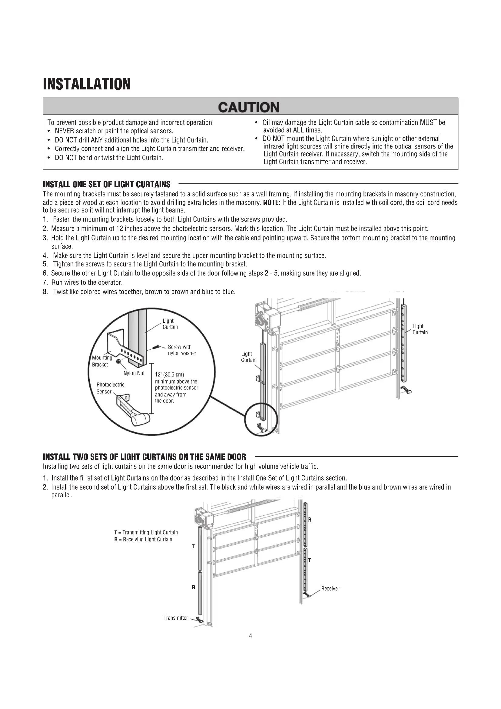
Technical line drawing of a mechanical assembly with spring and frame components (no text or symbols)CE
LiftMaster
845 Larch Avenue
Elmhurst, IL 60126-1196
LiftMaster®
INTRODUCTION
WARNING
To prevent possible SERIOUS INJURY or DEATH from a closing door:
- Be sure to DISCONNECT POWER to the operator BEFORE installing the Light Curtain.
- The door MUST be in the fully opened or closed position BEFORE installing the Light Curtain.
- Correctly connect and align the Light Curtain transmitter and receiver.
-
The Light Curtain is for use with LiftMaster® Commercial Doors. Use with ANY other product voids the warranty.
-
DO NOT use this product for the protection of dangerous machinery or in explosive atmospheres or radioactive environments. Use ONLY specific and approved types of devices for such applications.
- The Light Curtain MUST be installed ONLY by authorized and fully trained personnel.
- LiftMaster Monitored Entrapment Protection devices are required in addition to the Light Curtain. The Light Curtain may NOT be used as the sole entrapment protection device for ANY entrapment zone.
IMPORTANT INFORMATION ABOUT THE LIGHT CURTAIN
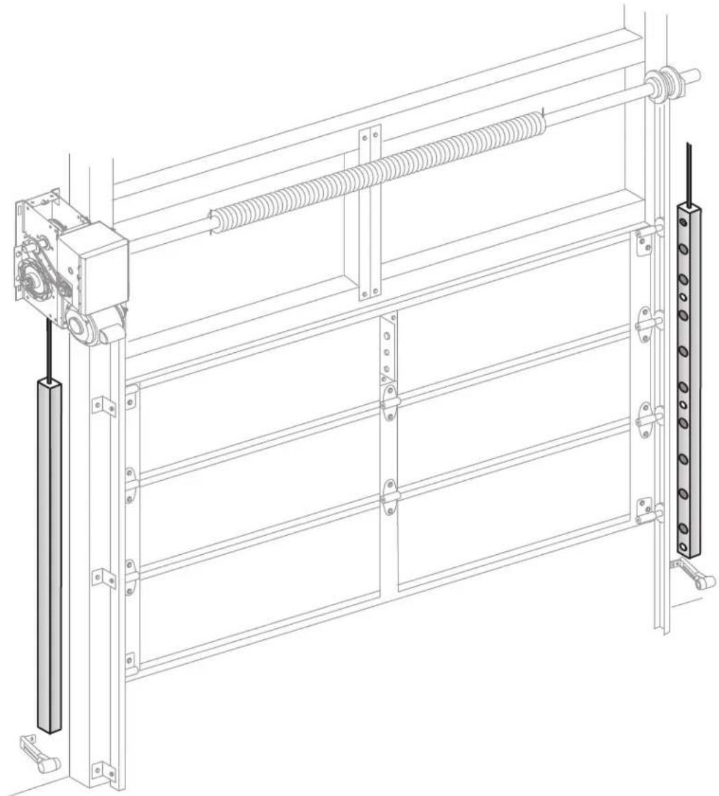
LiftMaster® Light Curtain (Model LC-36A) is an ancillary entrapment protection device used with sectional and rolling doors that is designed with 8 optical sensors that form 22 total invisible light beams. These light beams create a cross-pattern or netting effect for maximum protection against entrapment. When properly connected and aligned, the Light Curtain will detect an obstruction in the path of the light beams. If an obstruction breaks any light beam while the door is closing, the operator will stop and reverse to the full open position. The invisible light beam must be unobstructed. No part of the door (or door tracks, springs, hinges, rollers or other hardware) may interrupt the light beam while the door is closing.
The Light Curtain Transmitter must be installed facing the Light Curtain Receiver across the entrapment zone, 12° (30.5 cm) above the primary monitored entrapment protection device. The minimum installation width is 3 feet (.91 m) and the maximum width is 33 feet (10 m).
text_image
Light Curtain Transmitter Receiver 12" (30.5 cm) minimum above the photoelectric sensors and away from the door 6" (15 cm) maximum above the floor and away from the door Secondary entrapment protection ONLY Primary entrapment protection Primary Monitored Entrapment Protection Device (Photoelectric Sensors) Transmitter Light Curtain ReceiverINTRODUCTION
The images in this document are for reference only and your product may look different.
APPLICATION
The Light Curtain is compatible with LiftMaster Heavy, Standard, and Medium Duty Logic, FDC, FDCL, FDOA, FDOB, and Egress Commercial Door Operators. The Light Curtain is approved for track mounting. The Light Curtain is for indoor use only but may be installed in areas exposed to rain or moisture.
SPECIFICATIONS
Optical
Operating range: 3 - 33 feet (.91 - 10 meters)
Coverage area: 36" (91.4 cm) detection zone
Number of optical sensors: 8
Number of invisible light beams: 22
Receiver LED: Green
Transmitter LED: Amber
Electrical
Current Draw 40 mA
Supply voltage: 18 to 30 volts AC or DC
Output Type: .....Solid-state Relay, Normally Open (N.O.) when energized
Mechanical
Housing material: Aluminum, anodized
Cable length: 6'6" (2m)
Enclosure rating: NEMA 4
Operating temperature range: -40^ to +140^ ( -40^ to +60^ )
Storage temperature range: ....- 40°F to +185°F (- 40°C to +85°C)
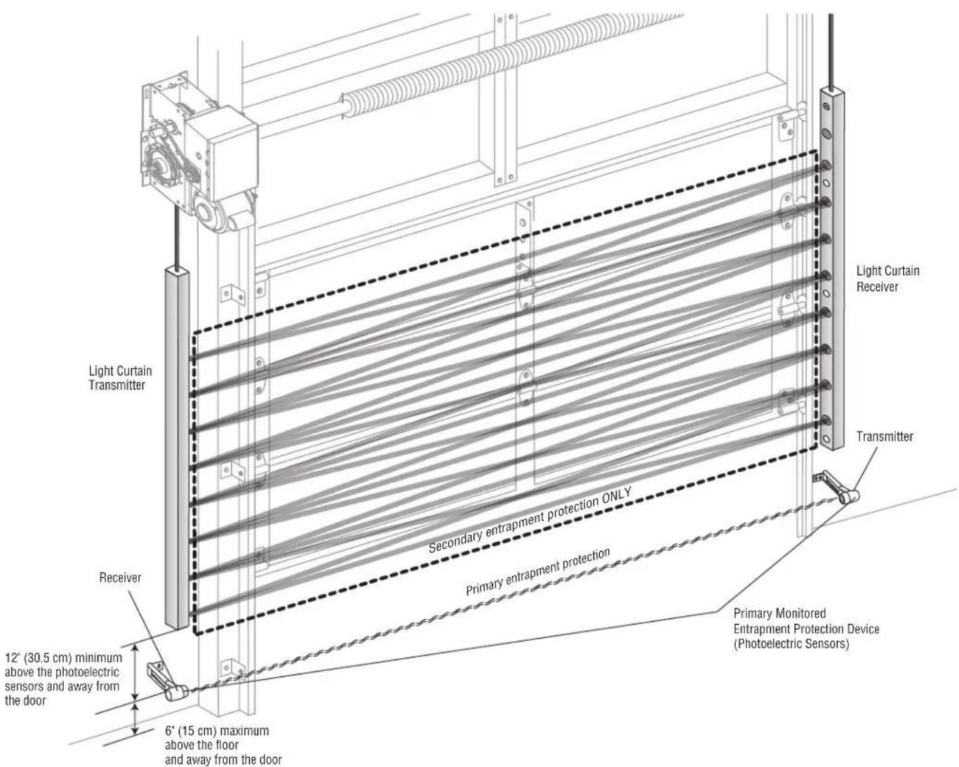
Dimensions
text_image
LED 3' 8.25' (112 cm) 2' 9.5' (86.1 cm) 1' 6.23' (46.3 cm) .2" (5 mm) .47" (12 mm) .27" (7 mm)44" (111.8 cm) length with 36" (91.4 cm) detection zone
ACCESSORIES
Conduit kit with 2 junction boxes and 2 fl exible cables.
Plug-In Power Supply 100MAPS
For medium-duty LiftMaster commercial door operators with low current capability. Also for use with Logic operators for additional power to operate the Light Curtains.
CARTON INVENTORY
Not Shown
- Screws, Washers, and Nuts with Nylon Insert
- Wire Connectors (6)
- Blocking Material
• Installation Manual
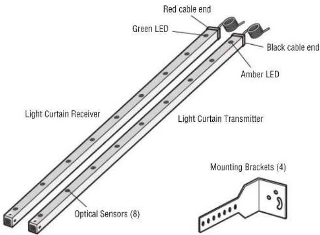
text_image
Red cable end Green LED Black cable end Amber LED Light Curtain Receiver Light Curtain Transmitter Optical Sensors (8) Mounting Brackets (4)INSTALLATION
CAUTION
To prevent possible product damage and incorrect operation:
• NEVER scratch or paint the optical sensors.
• DO NOT drill ANY additional holes into the Light Curtain.
- Correctly connect and align the Light Curtain transmitter and receiver.
• DO NOT bend or twist the Light Curtain.
- Oil may damage the Light Curtain cable so contamination MUST be avoided at ALL times.
- DO NOT mount the Light Curtain where sunlight or other external infrared light sources will shine directly into the optical sensors of the Light Curtain receiver. If necessary, switch the mounting side of the Light Curtain transmitter and receiver.
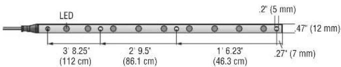
INSTALL ONE SET OF LIGHT CURTAINS
The mounting brackets must be securely fastened to a solid surface such as a wall framing. If installing the mounting brackets in masonry construction, add a piece of wood at each location to avoid drilling extra holes in the masonry. NOTE: If the Light Curtain is installed with coil cord, the coil cord needs to be secured so it will not interrupt the light beams.
- Fasten the mounting brackets loosely to both Light Curtains with the screws provided.
- Measure a minimum of 12 inches above the photoelectric sensors. Mark this location. The Light Curtain must be installed above this point.
- Hold the Light Curtain up to the desired mounting location with the cable end pointing upward. Secure the bottom mounting bracket to the mounting surface.
- Make sure the Light Curtain is level and secure the upper mounting bracket to the mounting surface.
- Tighten the screws to secure the Light Curtain to the mounting bracket.
- Secure the other Light Curtain to the opposite side of the door following steps 2 - 5, making sure they are aligned.
- Run wires to the operator.
- Twist like colored wires together, brown to brown and blue to blue.
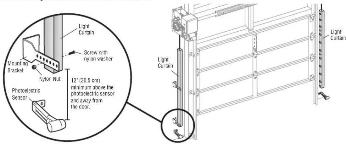
text_image
Light Curtain Mounting Bracket Nylon Nut Screw with nylon washer 12' (30.5 cm) minimum above the photoelectric sensor and away from the door. Photoelectric Sensor Light Curtain Light CurtainINSTALL TWO SETS OF LIGHT CURTAINS ON THE SAME DOOR
Installing two sets of light curtains on the same door is recommended for high volume vehicle traffic.
- Install the first set of Light Curtains on the door as described in the Install One Set of Light Curtains section.
- Install the second set of Light Curtains above the first set. The black and white wires are wired in parallel and the blue and brown wires are wired in parallel.
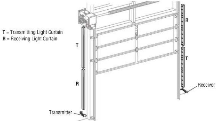
text_image
T = Transmitting Light Curtain R = Receiving Light Curtain T R Transmitter ReceiverINSTALLATION
INSTALL MULTIPLE LIGHT CURTAINS ON ADJACENT DOORS
When installing more than one set of Light Curtains on adjacent doors, blocking material must be attached to the center Light Curtains (as shown) to prevent cross-talk that could occur due to the close proximity of the Light Curtain sensors.
- Thread mounting screws through the Light Curtain, blocking material and bracket, and loosely secure with locking nylon nut.
Follow steps 2 - 8 of the Install One Set of Light Curtains section.
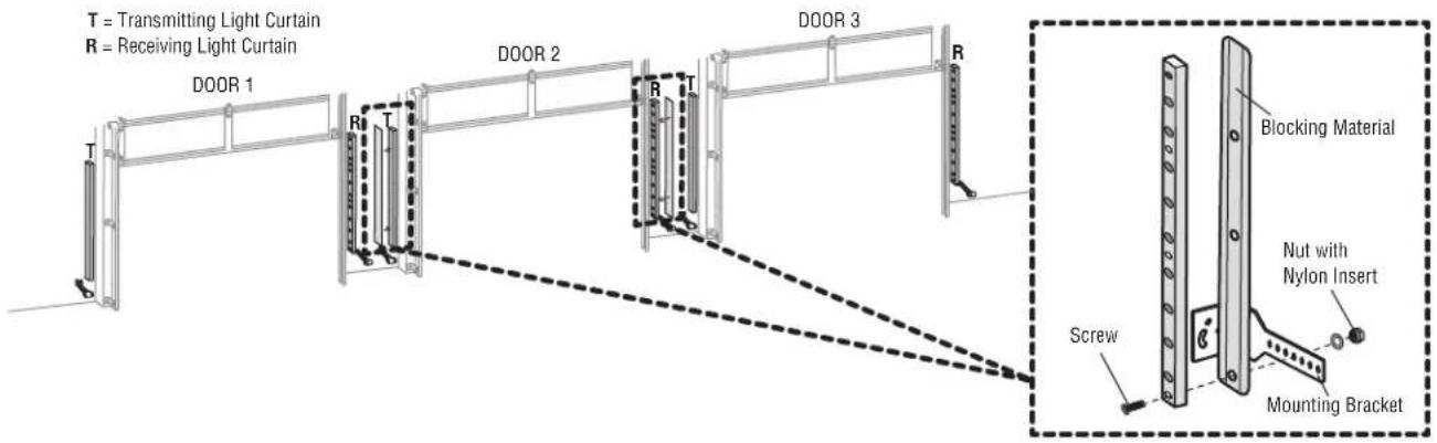
text_image
T = Transmitting Light Curtain R = Receiving Light Curtain DOOR 1 DOOR 2 DOOR 3 R T R T R Blocking Material Nutm with Nylon Insert Screw Mounting BracketPOWER WIRING
Do not run wiring in the same conduit with AC power. If installing on a medium duty LiftMaster commercial door operator, a 22 Vdc to 24 Vdc 100 mA Plug-In Power Supply is required (refer to Accessories).
- Disconnect power to the operator.
- Connect the wires from the Light Curtain to the operator as illustrated below (follow the instructions according to your operator type).
- Reconnect power to the operator.
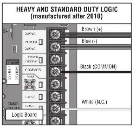
text_image
HEAVY AND STANDARD DUTY LOGIC (manufactured after 2010) 35VAC 3VAC 24VAC POWER 24VAC TIMER OFFSET COMMON MAS LMEP: EDGE: Logic Board Brown (+) Blue (-) Black (COMMON) White (N.C.)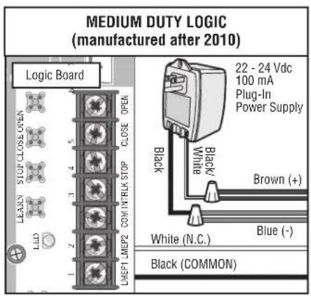
text_image
MEDIUM DUTY LOGIC (manufactured after 2010) Logic Board 22 - 24 Vdc 100 mA Plug-In Power Supply Black/White Brown (+) Blue (-) White (N.C.) Black (COMMON)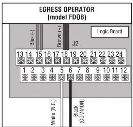
text_image
EGRESS OPERATOR (model FDOB) Blue (-) Brown (+) J2 Logic Board 13 14 15 16 17 18 19 20 21 22 23 24 1 2 3 4 5 6 7 8 9 10 11 12 White (N.C.) Black (COMMON)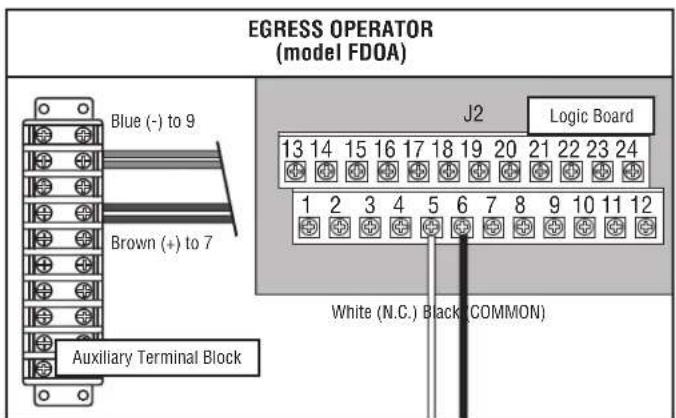
text_image
EGRESS OPERATOR (model FDOA) Blue (-) to 9 Brown (+) to 7 Auxiliary Terminal Block J2 Logic Board 13 14 15 16 17 18 19 20 21 22 23 24 1 2 3 4 5 6 7 8 9 10 11 12 White (N.C.) Black (COMMON)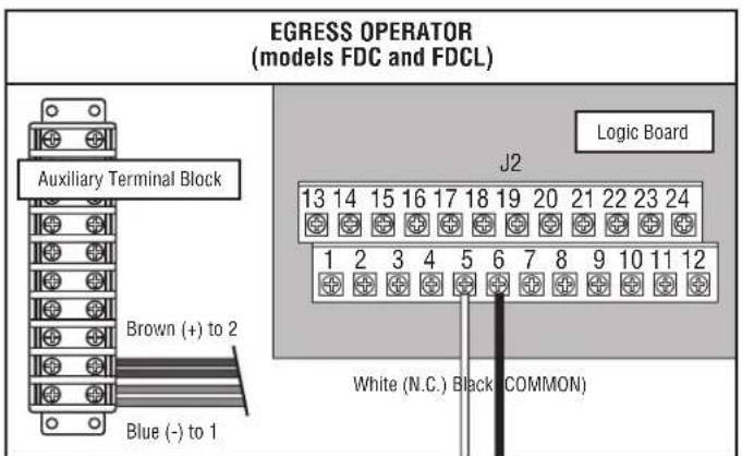
text_image
EGRESS OPERATOR (models FDC and FDCL) Auxiliary Terminal Block Brown (+) to 2 Blue (-) to 1 J2 Logic Board 13 14 15 16 17 18 19 20 21 22 23 24 1 2 3 4 5 6 7 8 9 10 11 12 White (N.C.) Black (COMMON)FINISH INSTALLATION
ALIGN THE LIGHT CURTAINS
The Light Curtain transmitter and receiver must be aligned. When properly wired and aligned the amber and green LEDs will be ON. The amber LED is located on the Light Curtain Transmitter and the green LED is located on the Light Curtain Receiver. If the amber and green LEDs are not on, refer to the table below.
- Open and close the door for one complete cycle to let the operator register the Light Curtain.
| AMBER LED GREEN LED STATUS SOLUTION | |||
| OFF OFF No power Check wiring. | |||
| ON Blinks • Light Curtain receiver and transmitter are not aligned • Adjust the Light Curtains to correct alignment• Obstructed light beam • Remove the obstruction• Defective Light Curtain Receiver • Replace Light Curtain receiver and transmitter (Model LC-36A) | |||
TEST THE PRIMARY AND ANCILLARY ENTRAPMENT PROTECTION
It is the responsibility of the specifier, purchaser, and installer to ensure that, on completion, the installation of the Light Curtain complies with all relevant federal, state, and local codes and regulations.
TEST THE LIGHT CURTAIN (ANCILLARY ENTRAPMENT PROTECTION)
- With the door in the full open position, press the close button.
- While the door is closing, obstruct any of the invisible light beams on the Light Curtain (the green LED on the Light Curtain Receiver will blink when the invisible light beam is obstructed). The door should stop and reverse.
TEST THE PHOTOELECTRIC SENSORS (PRIMARY ENTRAPMENT PROTECTION)
- With the door in the full open position place an obstruction in the path of the photoelectric sensors and press the close button. The operator should not move.
- Remove the obstruction and press the close button. The door should close.
MAINTENANCE
Periodically, check the following:
- Examine the optical sensors, ensuring they are clear of dirt and dust. If necessary, clean the front surface with a soft towel. Never use solvents, cleaners or mechanically abrasive towels to clean the Light Curtains because this can damage the optical sensors. Avoid direct, high-pressure water spray to clean the Light Curtains. Do not scratch the surface of the optical sensors when cleaning the Light Curtains.
- Check the mounting brackets, make sure they are securely fastened to the mounting surfaces. Tighten if necessary.
- Check that the Light Curtain cables are secured properly.
NOTICE: To comply with FCC and/or Industry Canada (IC) rules, adjustment or modifications of this digital device are prohibited. THERE ARE NO OTHER USER SERVICEABLE PARTS. Any changes or modifications not expressly approved by the party responsible for compliance could void the user's authority to operate the equipment.
This device complies with Part 15 of the FCC rules and IC License-Exempt RSS Standard(s). Operation is subject to the following two conditions: (1) this device may not cause harmful interference, and (2) this device must accept any interference received, including interference that may cause undesired operation.
natural_image
Technical line drawing of a mechanical assembly with spring and frame components (no text or symbols)CE
LiftMaster
845 Larch Avenue
Elmhurst, IL 60126-1196
LiftMaster®