CPSUN4G - Door or gate automation LIFT-MASTER - Free user manual and instructions
Find the device manual for free CPSUN4G LIFT-MASTER in PDF.
| Brand | LIFT-MASTER |
| Model | CPSUN4G |
| Product Type | Photoelectric entrapment protection sensor |
| Application | Commercial doors and barriers |
| Actuator Compatibility | LiftMaster series FDC, FDCL, FDO, LGE, Logic 3/4/5, CSL24V, CSW24V, RSL12V, RSW12V, LA400, LA412, LA500, HCTDCU, LA400PKGU, LA412PKGU, LA500PKGU, CSL24U, CSW24U, RSL12U, RSW12U, CSW200501U, CSW200101U, SL3000501U, SL3000101U, SL585U series, SL595U series |
| Detection Range | 2.1 m to 13.7 m (7 to 45 ft) |
| Door Mounting Height | ≤ 15 cm (6 in) above ground |
| Barrier Mounting Height | ≤ 69.8 cm (27.5 in) above ground, recommended 53.3 cm (21 in) |
| Beam Type | Invisible light |
| Power Supply | Via actuator (20 gauge copper wire minimum) |
| Cable Length Provided | 91.4 cm (36 in) per sensor |
| LED Indicators | Green on transmitter, yellow on receiver |
| Main Functions | Obstacle detection during closing, reversal of travel |
| Protection | Monitored (entrapment protection device) |
| Installation | Floor, wall, door track or post mounting |
| Housing Material | Not specified (moisture resistant) |
| Warranty | 1 year |
| Customer Service | 1-800-528-2806, LiftMaster.com |
| Maintenance | Check alignment, clear obstacles on the beam |
| Safety | Disconnect power before installation; comply with regulatory heights |
Frequently Asked Questions - CPSUN4G LIFT-MASTER
User questions about CPSUN4G LIFT-MASTER
0 question about this device. Answer the ones you know or ask your own.
Ask a new question about this device
Download the instructions for your Door or gate automation in PDF format for free! Find your manual CPSUN4G - LIFT-MASTER and take your electronic device back in hand. On this page are published all the documents necessary for the use of your device. CPSUN4G by LIFT-MASTER.
USER MANUAL CPSUN4G LIFT-MASTER
MODELS CPS-UN4 AND CPSUN4G
INTRODUCTION
APPLICATION
NOTE: The images throughout this manual are for reference and your product may look different.
The Commercial Protector System is suitable for use in applications where the photoelectric sensors will be exposed to moisture. The CPS-UN4 and CPSUN4G are LiftMaster Monitored Entrapment Protection (LMEP) devices and are compatible with the following operators:
| LiftMasterCommercial Door Operators | Models FDC, FDCL, FDO, and LGE, Medium Duty Logic, Logic 3, Logic 4, and Logic 5 |
| LiftMaster Legacy Gate Operators | Models CSL24V, CSW24V, RSL12V, RSW12V, LA400, LA412 and LA500 |
| LiftMaster 2016 UL 325 Gate Operators | Models HCTDCU, LA400PKGU, LA412PKGU, LA500PKGU, CSL24U, CSW24U, RSL12U, RSW12U, CSW200501U, CSW200101U, SL3000501U, SL3000101U, SL585U family, and SL595U family |
IMPORTANT INFORMATION ABOUT THE PHOTOELECTRIC SENSOR
Be sure power to the operator is disconnected.
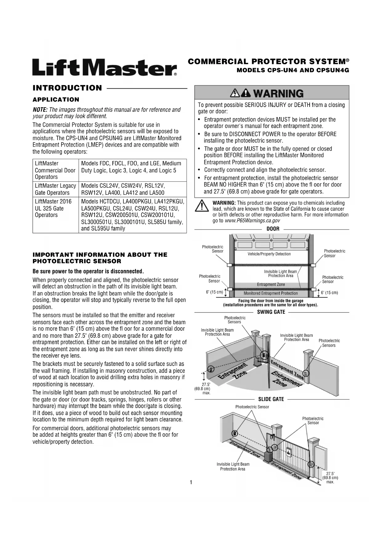
When properly connected and aligned, the photoelectric sensor will detect an obstruction in the path of its invisible light beam. If an obstruction breaks the light beam while the door/gate is closing, the operator will stop and typically reverse to the full open position.
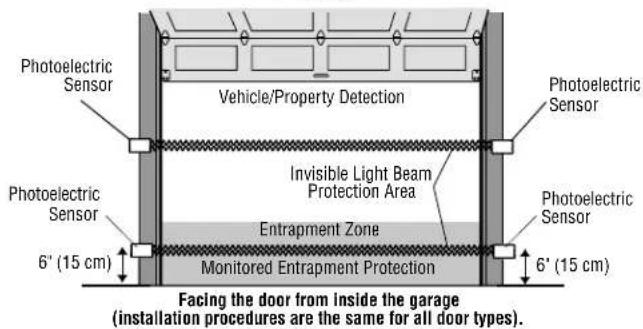
The sensors must be installed so that the emitter and receiver sensors face each other across the entrapment zone and the beam is no more than 6" (15 cm) above the floor for a commercial door and no more than 27.5" (69.8 cm) above grade for a gate for entrapment protection. Either can be installed on the left or right of the entrapment zone as long as the sun never shines directly into the receiver eye lens.
The brackets must be securely fastened to a solid surface such as the wall framing. If installing in masonry construction, add a piece of wood at each location to avoid drilling extra holes in masonry if repositioning is necessary.
The invisible light beam path must be unobstructed. No part of the gate or door (or door tracks, springs, hinges, rollers or other hardware) may interrupt the beam while the door/gate is closing. If it does, use a piece of wood to build out each sensor mounting location to the minimum depth required for light beam clearance.
For commercial doors, additional photoelectric sensors may be added at heights greater than 6" (15 cm) above the floor for vehicle/property detection.
⚠️ WARNING
To prevent possible SERIOUS INJURY or DEATH from a closing gate or door:
- Entrapment protection devices MUST be installed per the operator owner's manual for each entrapment zone.
- Be sure to DISCONNECT POWER to the operator BEFORE installing the photoelectric sensor.
- The gate or door MUST be in the fully opened or closed position BEFORE installing the LiftMaster Monitored Entrapment Protection device.
- Correctly connect and align the photoelectric sensor.
- For entrapment protection, install the photoelectric sensor BEAM NO HIGHER than 6" (15 cm) above the floor for door and 27.5" (69.8 cm) above grade for gate operators.

WARNING: This product can expose you to chemicals including lead, which are known to the State of California to cause cancer or birth defects or other reproductive harm. For more information go to www.P65Warnings.ca.gov
DOOR
text_image
Photoelectric Sensor Vehicle/Property Detection Photoelectric Sensor Invisible Light Beam Protection Area Photoelectric Sensor Photoelectric Sensor Entrapment Zone Monitored Entrapment Protection 6' (15 cm) 6' (15 cm) Facing the door from inside the garage (installation procedures are the same for all door types).SWING GATE
text_image
Photoelectric Sensors Invisible Light Beam Protection Area Invisible Light Beam Protection Area Photoelectric Sensors Entrapment Zone Entrapment Zone 27.5° (69.8 cm) max.SLIDE GATE
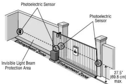
text_image
Photoelectric Sensor Photoelectric Sensor Entrapment Zone Invisible Light Beam Protection Area Entrapment Zone 27.5° (69.8 cm) max.INSTALLATION
ASSEMBLE AND MOUNT THE BRACKETS
Make sure the brackets are aligned so the photoelectric sensors will face each other across the entrapment zone. The brackets can be mounted on the ground, door track, or wall.
DOOR
Mount sensors no more than 6" (15 cm) above the floor and at a width between 7'-45' (2.1 m - 13.7 m).
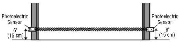
text_image
Photoelectric Sensor 6" (15 cm) Photoelectric Sensor 6" (15 cm)GATE
Mount within 5" (12.7 cm) of the moving gate panel with a maximum height of 27.5" (69.8 cm) above grade (21" [53.3 cm] is recommended) and at a width between 7'-45' (2.1 m - 13.7 m). The recommended mounting location is on the inside of the gate.
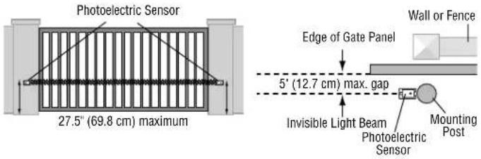
text_image
Photoelectric Sensor 27.5" (69.8 cm) maximum Edge of Gate Panel 5' (12.7 cm) max. gap Invisible Light Beam Photoelectric Sensor Mounting Post Wall or FenceAssemble to either side Flip one bracket and
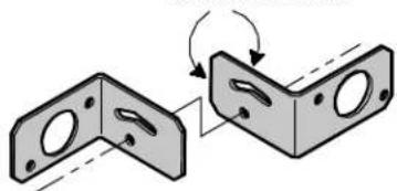
Determine the confi guration for your brackets. The assembly of the brackets will vary depending on your installation.
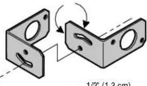
text_image
1/2" (1.3 cm)assemble to either side
natural_image
Diagram showing two views of a mechanical bracket with holes and mounting holes, connected by an arrow indicating rotation (no text or symbols present)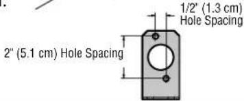
text_image
1/2" (1.3 cm) Hole Spacing 2" (5.1 cm) Hole SpacingBRACKET ASSEMBLY CONFIGURATIONS
DOOR TRACK INSTALLATION (FOR DOOR ONLY)
- Drill 1/4" holes in each track and securely fasten the bracket with the track bolts. NOTE: Always use a fl at washer next to the radius slot. To vertically attach to 2 x 4 wall stud it may become necessary to rotate bracket to prevent wood from splitting.
- Insert the sensor into the bracket and fasten with the hex mounting nut and lock washer.
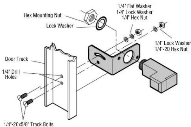
text_image
Hex Mounting Nut Lock Washer 1/4" Flat Washer 1/4" Lock Washer 1/4" Hex Nut Door Track 1/4" Drill Holes 1/4"-20x5/8" Track Bolts 1/4" -20x5/8" Track BoltGROUND OR WALL INSTALLATION
- Fasten the bracket with the track bolts. NOTE: Always use a fl at washer next to the radius slot. Putting track bolts in slots will prevent brackets from pivoting.
- Attach the bracket assembly to the wall with lag screws (provided) or to the ground with concrete anchors (not provided).
- Insert the sensor into the brackets and fasten with the hex mounting nut and lock washer.
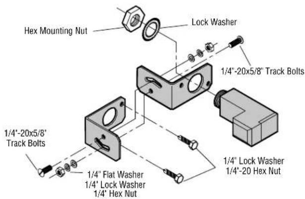
text_image
Hex Mounting Nut Lock Washer 1/4"-20x5/8" Track Bolts 1/4"-20x5/8" Track Bolts 1/4" Flat Washer 1/4" Lock Washer 1/4" Hex Nut 1/4" Lock Washer 1/4"-20 Hex NutINSTALLATION
CONDUIT CONNECTIONS
-
Disconnect power to the operator.
-
Use a liquid tight fitting (1/2" [1.3 cm] trade size) with sealing washer to connect to sensors. The sensors are provided with 36" (91.4 cm) long leads. LiftMaster recommends the use of a liquid tight junction box near each sensor to make the connection to the sensor leads. Use rigid or flexible liquid tight conduit (depending on local codes) from junction boxes to operator. IMPORTANT: Use a minimum size 20 ga. copper wire for connection between the sensors and the operator.
DOOR
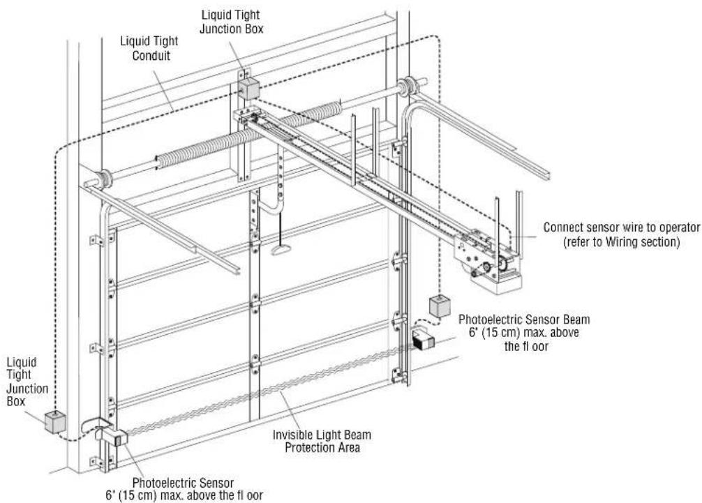
text_image
Liquid Tight Junction Box Liquid Tight Conduit Connect sensor wire to operator (refer to Wiring section) Liquid Tight Junction Box Photoelectric Sensor Beam 6" (15 cm) max. above the floor Invisible Light Beam Protection Area Photoelectric Sensor 6' (15 cm) max. above the floorGATE
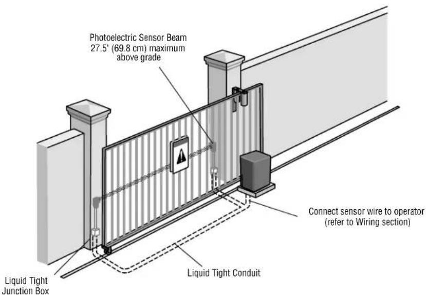
text_image
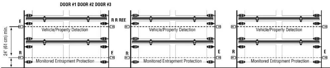
Photoelectric Sensor Beam 27.5" (69.8 cm) maximum above grade Liquid Tight Junction Box Connect sensor wire to operator (refer to Wiring section) Liquid Tight ConduitRecommended installation for adjacent doors and more than one set of photoelectric sensors. For LOGIC 4 and LOGIC 5 Operators, a CPS3CARD is required to wire a second set of monitored photoelectric sensors.
text_image
DOOR #1 DOOR #2 DOOR #3 E R REE Vehicle/Property Detection R Monitored Entrapment Protection E R Monitored Entrapment Protection Vehicle/Property Detection E R Monitored Entrapment Protection 24" (61 cm) min.6" (15 cm) max. above floor
R = Receiver Sensor E = Emitter Sensor
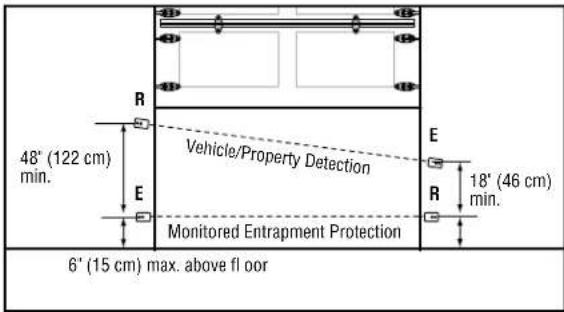
text_image
48" (122 cm) min. R E Vehicle/Property Detection Monitored Entrapment Protection E R 18" (46 cm) min. 6" (15 cm) max. above floorWIRING
text_image
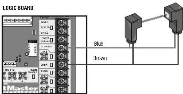
LOGIC BOARD LEARN STOP CLOSE OPE LED LWP1 LA2 P2 COM/INTLK STOP CLOSE OPE LWP1 LA2 P2 COM/INTLK STOP CLOSE OPE Blue BrownLOGIC 3, 4, AND 5
text_image
LOGIC BOARD Blue BrownMODELS FDC, FDCL, FDO, AND LGE
LOGIC BOARD
text_image
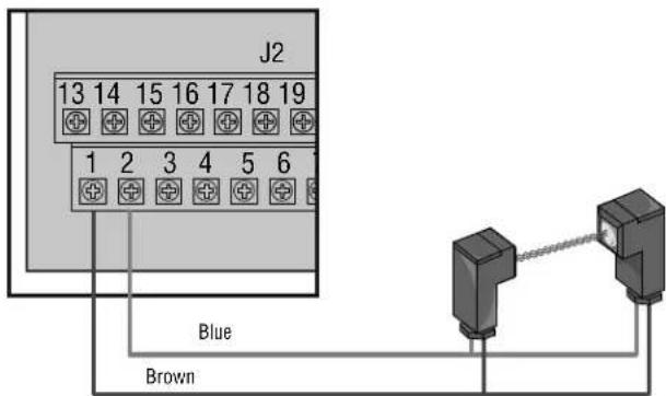
J2 13 14 15 16 17 18 19 1 2 3 4 5 6 Blue BrownWIRING
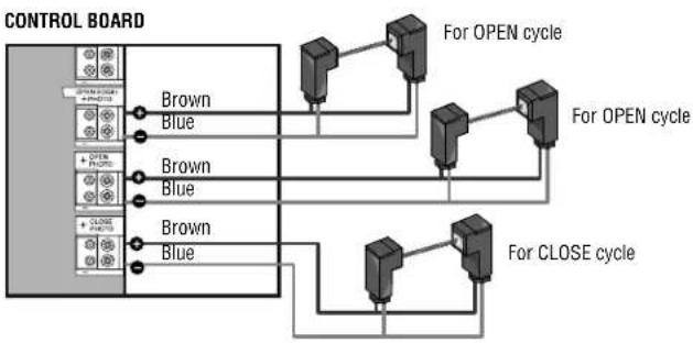
The photoelectric sensors can be wired to function for either the open or close cycle depending on where they are wired on the control board. Refer to your gate operator manual for more information.
text_image
CONTROL BOARD EXIT CLOSE TYPE INTERLOCK CLOSE OPEN OPEN OPEN Blue Brown Brown Blue For CLOSE cycle For OPEN cycleMODELS LA412, RSW12V, AND RSL12V
flowchart
graph TD
    A["CONTROL BOARD"] --> B["Brown"]
    A --> C["Blue"]
    D["For OPEN cycle"] --> E["Red/Blue 1"]
    F["For OPEN cycle"] --> G["Red/Blue 2"]
    H["For CLOSE cycle"] --> I["Red/Blue 3"]
    J["For CLOSE cycle"] --> K["Red/Blue 4"]
MODEL LA400
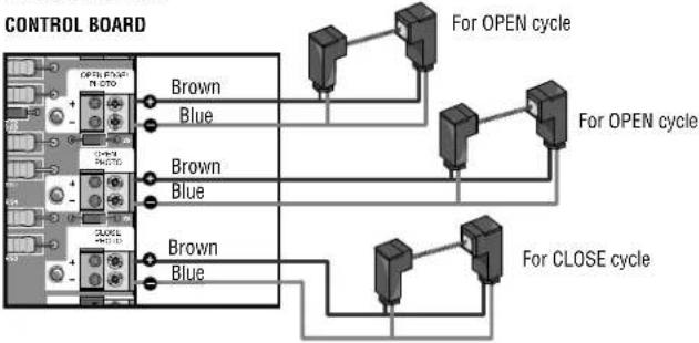
flowchart
graph TD
    A["CONTROL BOARD"] --> B["For OPEN cycle"]
    A --> C["For CLOSE cycle"]
    B --> D["Brown Blue"]
    B --> E["Brown Blue"]
    C --> F["Brown Blue"]
    C --> G["Brown Blue"]
2016 UL 325 GATE OPERATORS
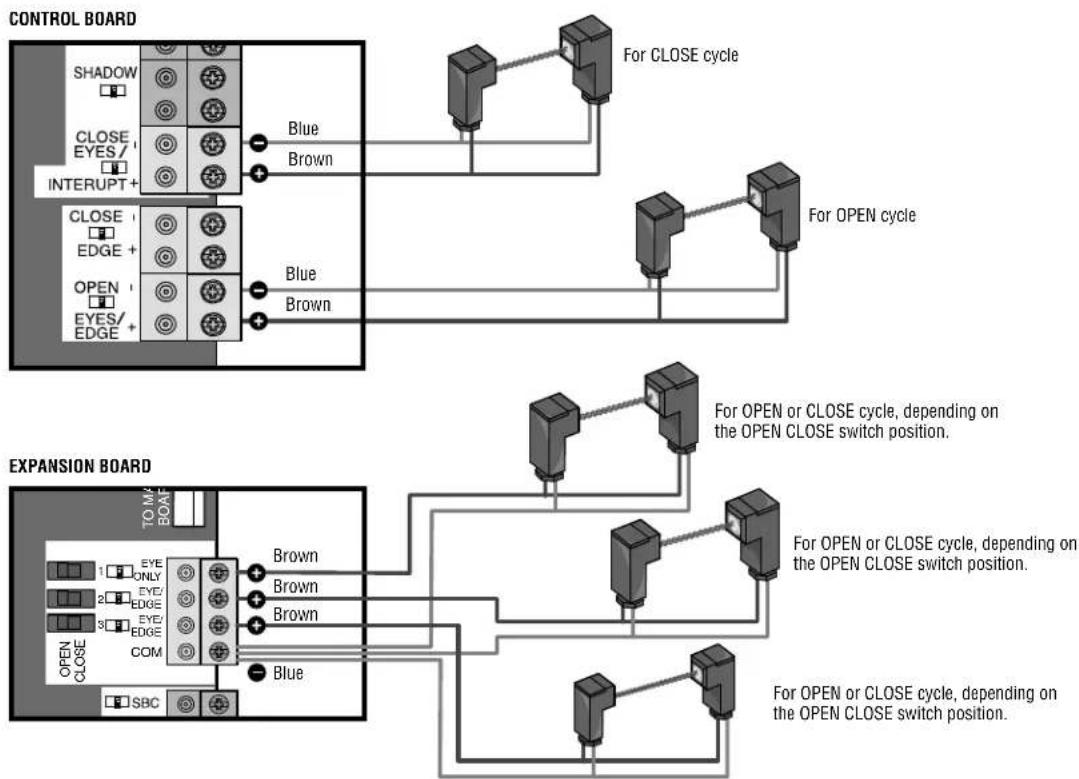
flowchart
graph TD
    subgraph CONTROL BOARD
        A["SHADOW"] --> B["CLOSE EYES/ INTERRUPT +"]
        C["CLOSE EDGE +"] --> D["OPEN EYES/EDGE +"]
    end
    subgraph EXPANSION BOARD
        E["EYE ONLY"] --> F["COMP COM"]
        G["EYE EDGE"] --> F
        H["EYE EDGE"] --> F
        I["SBC"] --> F
    end

    B --> J["Blue"]
    D --> K["Blue"]
    F --> L["Brown"]
    F --> M["Brown"]
    F --> N["Blue"]
    F --> O["Brown"]
    J --> P["For CLOSE cycle"]
    K --> Q["For OPEN cycle"]
    L --> R["For OPEN or CLOSE cycle, depending on the OPEN CLOSE switch position."]
    M --> S["For OPEN or CLOSE cycle, depending on the OPEN CLOSE switch position."]
    N --> T["For OPEN or CLOSE cycle, depending on the OPEN CLOSE switch position."]
    O --> U["For OPEN or CLOSE cycle, depending on the OPEN CLOSE switch position."]
TEST
- Connect power to the operator.
- Align the photoelectric sensors so the green LED on the emitter sensor and the yellow LED on the receiver sensor glow steadily.
- Press the OPEN button to fully open the door/gate.
- Press the CLOSE button to close the door/gate.
- For doors: Obstruct the light beam while the door is closing. The door should stop and reverse.
For gates: Obstruct the light beam while the gate is opening or closing. If closing, the gate should stop and reverse to the full open position. If opening, the gate should reverse for 4 seconds then stop.
The operator will not close if the indicator light in either sensor is not glowing steadily, alerting you to the fact that the sensor is misaligned or obstructed.
TROUBLESHOOTING
If the emitter sensor and receiver sensor indicator lights do not glow steadily after installation, check for:
• Photoelectric sensor alignment
- Obstruction
• Power to the operator
- A short or broken wire
- Incorrect wiring between photoelectric sensors and the operator
If the receiver sensor indicator light is off or flashing (and the invisible light beam path is not obstructed), check alignment of the sensors and/or for an open wire to the receiver sensor.
If the emitter sensor and receiver sensor indicator lights are both glowing steadily but interrupting the photoelectric sensors does not cause the door/gate to reverse when closing, check both sensors to make sure one sensor is the emitter and the other is a receiver sensor as indicated on the sensor housing.
NOTES:
- Direct sunlight to the receiver sensor may prevent the operator from closing even when both the emitter and receiver indicator lights are illuminated. Swapping the position of the emitter and receiver sensors will resolve this issue.
- To avoid nuisance blockages from snow, install a hood over the photoelectric sensors to keep the snow from obstructing the lenses.
• Professional service is required if the operator closes the door/gate when the photoelectric sensors are obstructed. - 2016 UL 325 gate operators have diagnostic codes related to entrapment protection devices. Refer to your gate operator manual or wiring diagram for a list of troubleshooting diagnostic codes.
WARRANTY
LiftMaster ^® warrants to the first consumer purchaser of this product that it is free from defect in materials and/or workmanship for a period of 1 year from the date of purchase.
FOR SERVICE OR TO ORDER REPAIR PARTS DIAL:
1-800-528-2806
LiftMaster.com