RVC 4.1 KH - Rear Camera BLAUPUNKT - Free user manual and instructions
Find the device manual for free RVC 4.1 KH BLAUPUNKT in PDF.
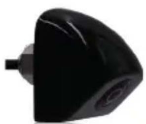
| Product type | Rear view camera |
| Brand | Blaupunkt |
| Model | RVC 4.1 KH |
| Video signal | CVBS |
| Video standard | NTSC |
| Effective resolution | 688 x 528 pixels |
| Power supply | 12 V DC |
| Power consumption | < 40 mA, < 0.35 W |
| Protection rating | IP67 |
| Operating temperature | -20 °C to +65 °C |
| Storage temperature | -30 °C to +80 °C |
| Minimum illumination | 0.1 lux |
| Included accessories | RCA extension cable 10 m (VK-RVC 4.X), signal filter (SF-RVC 4.X) |
| Main functions | Rear view with guide lines, mirror/normal image switch, guide lines switch, dual coil control function |
| Installation | Bumper or bracket mounting, recommended by a specialist; disconnect the battery before installation |
| Cleaning and maintenance | Clean regularly with a soft cloth; do not use high-pressure water jet |
| Safety | Do not modify the device; respect operating limits; professional installation recommended |
| Spare parts and repairability | No user-serviceable parts; accessories available (RCA cable, filter) |
Frequently Asked Questions - RVC 4.1 KH BLAUPUNKT
User questions about RVC 4.1 KH BLAUPUNKT
0 question about this device. Answer the ones you know or ask your own.
Ask a new question about this device
Download the instructions for your Rear Camera in PDF format for free! Find your manual RVC 4.1 KH - BLAUPUNKT and take your electronic device back in hand. On this page are published all the documents necessary for the use of your device. RVC 4.1 KH by BLAUPUNKT.
USER MANUAL RVC 4.1 KH BLAUPUNKT
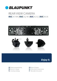
RVC 4.1 KH | RVC 4.2 W | RVC 4.3 U | RVC 4.4 A


Enjoy it.

Universal type installation location

Special type installation location

A. Installation Guide For Flush-Mount Camera

1. Check to be sure the hole saw used is with equal diameter to that of camera.

2. Adjust the camera to turn the UP arrow mark straight upwards.
3. Put the harness through the hole made on bumper before fixing the camera.

4. Put the camera into the hole and use your two thumbs to press it evenly for tight and flat mounting.
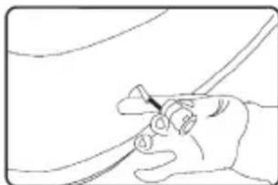
B. Installation Guide For Bracket-Mount Camera

- Choose a flat position near license plate light and make a small hole for the first screw with a drill.

- Use a screw driver to fix the first screw (but not tightly).

- Get the power/video cables connected, and then adjust the camera properly to find the best position for the other screw according to the camera image in monitor.

- Mark the position found for second screw and make a hole with a drill.

- Fix the second screw with a screw driver.
Remarks:
Beside flush and bracket mount cameras, we also have bolt mount camera series, which is mounted by following steps:
- Select suitable flat position near the license plate light and mark it.
- Drill a hole according to the bolt diameter.
- Put the bolt vertically (against ground) into the hole and fix the bolt with the screw supplied from inside.
- Some models come with up/down image switch option, and can be mounted with its bolt horizontal (against ground) and its lens downward.
| Video signal CVBS Current | Consumption | <40mA | |
| Signal NTSC Power <0.35W | |||
| Effective Pixels 688X52 8 Waterproof Grade IP67 | |||
| Voltage DC12V Operating | temperature range | -20 °C ~ +65 °C | |
| Min Illumination 0.1 Lux Storage | temperature range | -30 °C ~ +80 °C | |
| Optional accessories VK-RVC 4.X (10 meter RCA extension cable); SF-RVC 4.X (signal filter) | |||
| Other Rear view with parking line, formal/ mirror switch, parking line swich, dual-coil control dual functions | |||
WIRING DIAGRAM


The wiring diagram applies to most (but not all) camera models, and when making the connections, please also refer to the labels or marks on the wires.
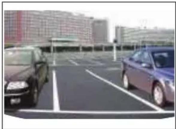

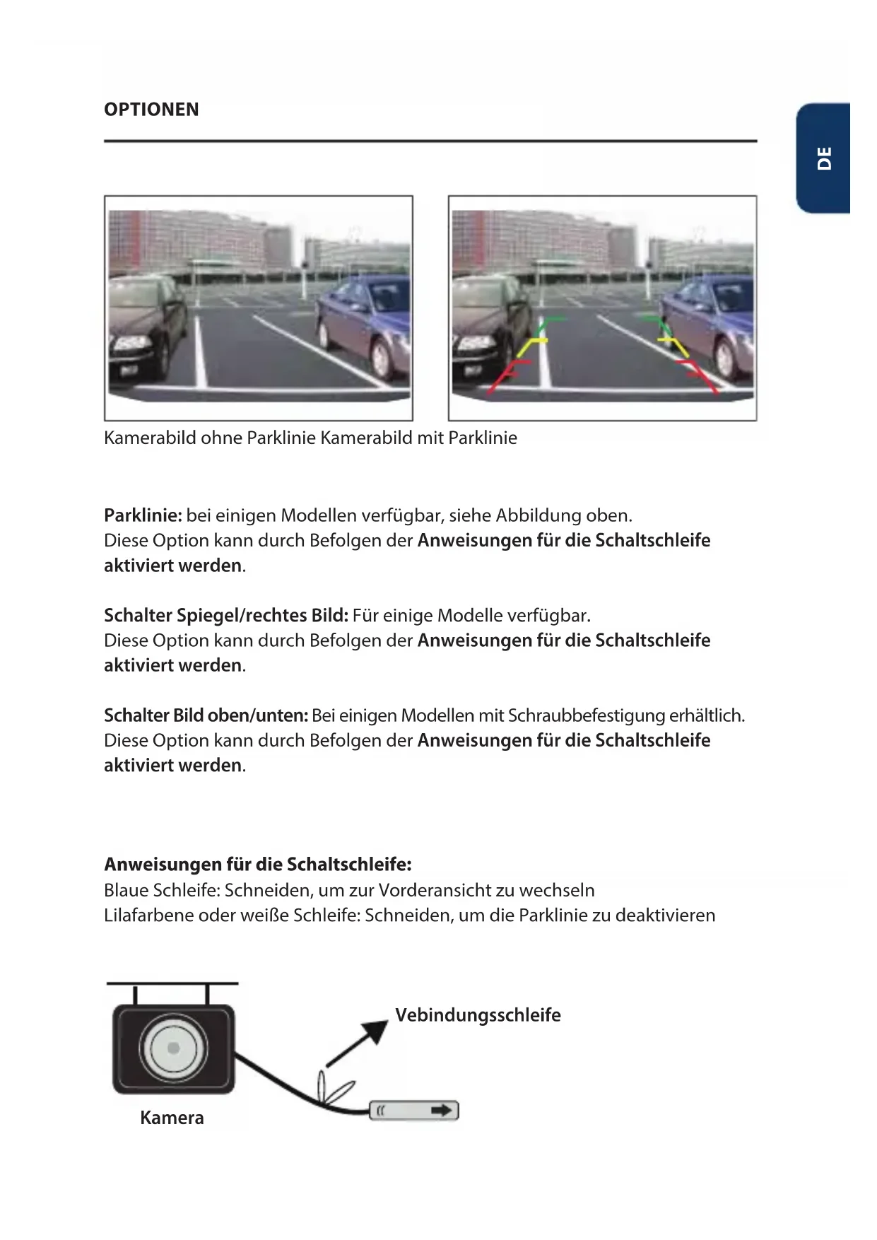
Camera Image w/o parking guide line Camera image with parking guide line
Parking Guide Line: Available on partial models, refer to image above. Option can be realized by following Switch Loop Instructions.
Mirror/right image switch: Available on partial models.
Option can be realized by following Switch Loop Instructions.
Up/down image switch: Available on partial bolt mount type models. Option can be realized by following Switch Loop Instructions.
Switch Loop Instructions:
Blue loop: Cut to switch to front view Purple or white loop: Cut to turn off parking line

- Some of the functions described in the instructions may be model-specific and may not be supported by every model.
- Do not modify or tamper with the device. There are no user-serviceable parts inside.
- Observe the performance limits of the device. Have repairs and, if necessary, installation done by a professional.
- Install the device only if you have needed experience installing such devices and are familiar with the vehicle's electrical system. Observe the information marked on the unit connections.
- Ensure that all wires transfer the correct signals or voltages.
- The installation of the radio must not interfere with or prevent the activation of airbags and other safety devices and/or controls.
- Disconnect the vehicle battery (negative terminal, ground) before installing the device, as doing otherwise may cause malfunctions or damage to the device or the vehicle electronics. Observe the vehicle manufacturer's safety instructions (airbag, alarm system, on-board computer, immobiliser, etc.).
- The rear (front) view camera functions technically as a driver assistance device, which cannot be taken as substitute for driver's responsibility when operating the vehicle.
- To keep the camera/monitor working properly, please clean the camera/monitor regularly to free it from dirt, water drops, snowdrops etc.
- Although the camera is designed to be waterproof, please do NOT use high-pressure water jet to wash the camera as this may break the glass lens.
- Keep the cables of the camera/monitor away from high temperature objects such as engine or exhaust.
- If the camera model you have comes without in-built LED lights, please turn on your license plate light for better vision at night or in dark areas.
- The camera/monitor are applicable to vehicles with DC 12V power output (10% higher or lower allowed), please do NOT use the 5.1 model on vehicles with DC 24V or other power output out of this range, otherwise it is very likely to get burned.
- The specifications of the camera/monitor are subject to change without prior notice.
Subject to technical changes, errors and misprints.
This material may only be reproduced, copied or distributed for personal use.
© Evo-Sales GmbH - all rights reserved.