ZIHB305 - Plane Zipper - Free user manual and instructions
Find the device manual for free ZIHB305 Zipper in PDF.

| Product Type | Planer / Jointer Combination |
| Model | ZIHB305 |
| Brand | Zipper |
| Power Supply | 230 V ~ 50 Hz |
| Power | 1500 W |
| Maximum Depth of Cut | 2 mm |
| Height Adjustment | 3 mm per crank turn |
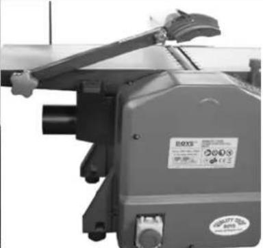
| Table Dimensions | 450 x 350 mm |
| Weight | 35 kg |
| Rotation Speed | 9000 rpm |
| Number of Blades | 2 |
| Protection | Emergency stop switch, cutting head protection |
| Functions | Jointing, planing |
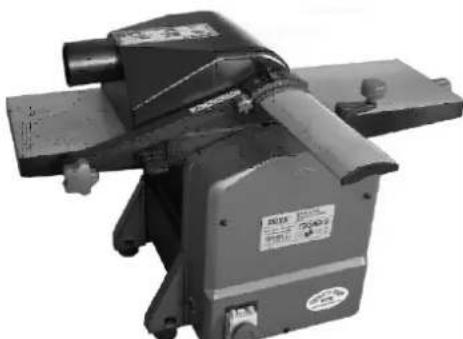
| Dust Extraction | Vacuum connection (adaptable hood) |
| Frame Material | Aluminum Cast |
| Maintenance | Lubrication every 100 h, blade changes, cleaning after each use |
| Safety | Automatic shutdown in case of overload, restart protection |
| Warranty | 2 years DIY use, 1 year professional use |
Frequently Asked Questions - ZIHB305 Zipper
User questions about ZIHB305 Zipper
0 question about this device. Answer the ones you know or ask your own.
Ask a new question about this device
Download the instructions for your Plane in PDF format for free! Find your manual ZIHB305 - Zipper and take your electronic device back in hand. On this page are published all the documents necessary for the use of your device. ZIHB305 by Zipper.
USER MANUAL ZIHB305 Zipper
EN USER MANUAL Compined planer and thicknesser
ES MANUAL DE INSTRUCCIONES Cepillo-regrueso
HR UPUTA ZA UPORABU Ravnalica i blanjalica
natural_image
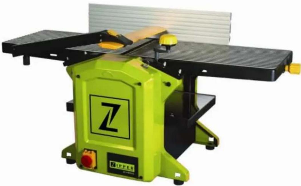
Green Zippers machine with black workpiece and yellow handle, no visible text or symbols on the machine itself.1 INHALT/ INDEX
1 INHALT/ INDEX 2
11.1 Intended Use....20
11.2 Remaining risk factors.... 21
12 ASSEMBLY 22
12.1 ASSEMBLY / ADJUSTMENT.... 22
13 OPERATION 23
13.1 Operation instructions.... 23
13.2 Planing 23
13.3 Thicknesser 24
14 MAINTENANCE 25
14.1 Maintenance plan 25
14.2 Replacing blades 25
14.3 Storage....26
14.4 Cleaning 26
14.5 Disposal....26
15 TROUBLE SHOOTING 26
16 PREFACIO (ES) 27
17 SEGURIDAD 28
19.1 Operation instructions.... 31
19.1 Cepillo 31
19.2 Regrueso 32
20 MANTENIMIENTO 32
EN EC-CONFORM: This product complies with the EC-directives.
EN READ THE MANUAL! Read the user and maintenance manual carefully and get familiar with the controls in order to use the machine correctly and to avoid injuries and machine defects.
ATTENTION! Ignoring the safety signs and warnings applied on the machine as well as ignoring the security and operating instructions can cause serious injuries and even lead to death.
EN Protective clothing!
EN Stop and pull out the power plug before any break and engine maintenance!

EN Only trained staff!
EN Operation with jewelry forbidden!
EN Warning about cut injuries!
EN Warning of rotating parts!
Please check the product contents immediately after receipt for any eventual transport damage or missing parts. Claims from transport damage or missing parts must be placed immediately after initial machine receipt and unpacking before putting the machine into operation. Please understand that later claims cannot be accepted anymore.
natural_image
Person using a machine tool on a workbench, no visible text or symbolsnatural_image
Close-up of a hand operating a wooden machine with a ball on the work (no visible text or symbols)ACHTUNG

natural_image
Close-up of a mechanical component with a metallic top and a white cup, no visible text or symbols.This manual contains important information and advice for the correct and safe use and maintenance of the Compined planer and thicknesser ZI-HB305.
Following the usual commercial name of the device (see cover) is substituted in this manual with the name "machine".
The manual is part of the machine and may not be stored separately. Read it profoundly before first use of the machine and keep it for later reference. When the machine is handed to other persons always put the manual to the machine.
Please follow the security instructions!
Please read the entire manual, to prevent misunderstandings, machine damage or even injuries! Due to continuous development of our products illustrations, pictures might differ slightly. If you however find errors in this manual, please inform us.

Technical changes excepted!
Copyright law
© 2018
This manual is protected by copyright law – all rights reserved. Especially the reprinting as well as the translation and depiction of pictures will be prosecuted by law. Court of jurisdiction is the Landesgericht Linz or the competent court for 4707 Schlüsslberg, AUSTRIA.
Customer Support
The machine must only be used for its intended purpose! Any other use is deemed to be a case of misuse.
To use the machine properly you must also observe and follow all safety regulations, the assembly instructions, operating and maintenance instructions lay down in this manual.
All people who use and service the machine have to be acquainted with this manual and must be informed about the machine's potential hazards.
It is also imperative to observe the accident prevention regulations in force in your area.
The same applies for the general rules of occupational health and safety.
The machine is used for:
Planing of wood in compliance with technical data. Specified maximum depth of cut (planer 2mm, thicknesser 1.5mm) and material dimensions.
Any manipulation of the machine or its parts is a misuse, in this case ZIPPER-MASCHINEN and its sales partners cannot be made liable for ANY direct or indirect damage.

WARNING
- Only use the planer knives that are permissible for this machine!
- Never use a damaged planer knives!
- Use the machine never with defective or without mounted guard HIGHEST RISK OF INJURY!
Ambient conditions
The machine may be operated:
humidity
max.
70%
temperature
+5^ to +40^ (+41^ to +104^)
The machine shall not be operated in areas exposed to increased fire or explosion hazard.
Prohibited use
• The operation of the machine outside the stated technical limits described in this manual is forbidden.
• The use of the machine not according with the required dimensions is forbidden.
- The use of the machine not being suitable for the use of the machine and not being certified is forbidden.
• Any manipulation of the machine and parts is forbidden.
• The use of the machine for any purposes other than described in this manual is forbidden.
• The unattended operation on the machine during the working process is forbidden!
- It is not allowed to leave the immediate work area during the work is being performed. Security instructions
Missing or non-readable security stickers have to be replaced immediately!
The locally applicable laws and regulations may specify the minimum age of the operator and limit the use of this machine!
To avoid malfunction, machine defects and injuries, read the following security instructions!

- Keep your work area dry and tidy! An untidy work area may cause accidents. Avoid slippery floor.
- Make sure the work area is lighted sufficiently
- Do not overload the machine
- Provide good stability and keep balance all times
- Avoid abnormal working postures! Make sure you stand squarely and keep balance at all times.
- Keep away from the running tool!

- Always stay focused when working. Reduce distortion sources in your working environment. The operation of the machine when being tired, as well as under the influence of alcohol, drugs or concentration influencing medicaments is forbidden.
• Respectively trained people only and only one person shall operate the machine.
- Do not allow other people, particularly children, to touch the machine or the cable. Keep them away from your work area.

• Make your workshop childproof.
• Make sure there is nobody present in the dangerous area. The minimum safety distance is 2m
- Wear suitable work clothes! Do not wear loose clothing or jewellery as they might get caught in moving parts and cause severe accidents! Wear a hair net if you have long hair.
- Use personal safety equipment: safety gloves, dust musk, ear protectors and safety goggles when working with the machine.
- Never leave the machine running unattended! Before leaving the working area switch the machine off and wait until the machine stops.
• Always disconnect the machine prior to any actions performed at the machine.
- Avoid unintentional starting
- Do not use the machine with damaged switch
- The plug of an electrical tool must strictly correspond to the socket. Do not use any adapters together with earthed electric tools
- Each time you work with an electrically operated machine, caution is advised! There is a risk of electric shock, fire, cutting injury;
- Protect the machine from dampness (causing a short circuit)
- Use power tools and machines never in the vicinity of flammable liquids and gases (danger of explosion)
- Check the cable regularly for damage
- When working with the machine outdoors, use extension cables suitable for outdoor use
- Do not use the cable to carry the machine or to fix the work piece
- Protect the cable from heat, oil and sharp edges
- Avoid body contact with earthed
• Before starting the machine remove any adjusting wrenches and screwdrivers
- Parts can cause severe cut injuries
- Keep any machine that is not being used out of reach of children
11.2 Remaining risk factors

WARNING
It is important to ensure that each machine has remaining risks. In the execution of all work (even the simplest) greatest attention is required. A safe working depends on you!
Even if the machine is used as required it is still impossible to eliminate certain residual risk factors totally. The following hazards may arise in connection with the machine's construction and design:
- Risk of injury to the hands / fingers by the tool and tool mount during operation.
- Risk of injury due to sharp edges of the workpiece, especially in non-fixed with a suitable tool / device workpiece.
- Risk of injury: hair and loose clothing, etc. can be captured and wound up! Safety regulations must be observed with regard to clothing.
- Risk of injury due to contacting with live electrical components.
- Risk of injury due to dust emissions, treated with harmful agents workpieces
- Risk of injury to the hearing by prolonged labor without hearing protection
- Risk of injury to the eye by flying debris, even with safety goggles.
These risk factors can be minimized through obeying all security and operation instructions, proper machine maintenance, proficient and appropriate operation by persons with technical knowledge and experience.
12 ASSEMBLY
12.1 ASSEMBLY / ADJUSTMENT
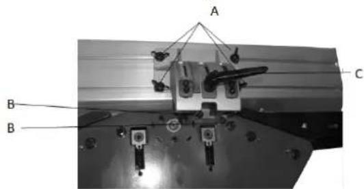
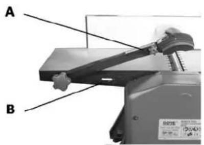
Angle fence
Fix the angle fence with 2 Socket head bolts (B) onto the machine. Then loosen the handle (C) to adjust the angle fence in position. Losen (A), angle fence can be moved to left or right.
| Absaugadapter | ABRICHTEN | DICKENHOBELN |
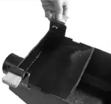 |  |  |
The dust chute has two keys that allow it to be attached to the table. For planers, install the adapter below the table. In the case of thick planes, remove the blade guard and then place the dust chute on the planing shaft and fix it with the keys in the holes provided for it.

ACHTUNG
For a clean operation, the connection of the Zi-HB305 to a dust collector is recommended in any case.
In enclosed rooms the connection to an exhaust system is obligatory.
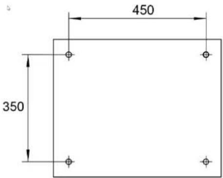
Machine Mounting
Attach the machine to a stable surface, such as a workbench. For good working results, the machine must be fixed in order to prevent unnecessary vibrations and the movement of the machine during operation. When using the machine to assemble furniture etc., ensure a suitably adapted and stable base.
13 OPERATION
Device to be operated in a perfect state only. Inspect the device visually every time it is to be used. Check in particular the safety equipment, electrical controls, electric cables and screwed connection for damage and if tightened properly. Replace any damaged parts before operating the device.
13.1 Operation instructions

WARNING
Perform all machine settings with the machine being disconnected from the power supply!


Notice
Dust Collector must be connected, otherwise the machine will not start.
13.2 Planing
Connecting the dust chute
natural_image
Mechanical device with labeled parts A and B, no visible text or symbols on the main body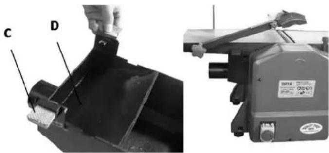
natural_image
Two technical diagrams showing a hand operating a mechanical component labeled C and D, alongside a machine with a label (no readable text or symbols beyond labels)Lift up the blade arm A so that the longitude holes B being exposed; Pull out the key C on both sides of the dust chute D; Move down the thickness table to the lowest position, and insert the dust chute D; The dust chute D is so positioned that both keys C are in line with the longitude holes B. Then push both keys C into the longitude holes B.
Planing of thin workpieces
In the case of thin workpieces, the planing shaft
Guard is over the whole planing shaft.
Feed of the workpiece indirectly with sliding wood.
Sets secure stand and guide the workpiece standing over the planer shaft. Never stand Right or directly behind the planing shaft.
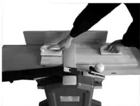
natural_image
Person operating a machine with hands on top (no visible text or symbols)Planing of small workpieces or Planks
Set the planing shaft cover so that only the part of the planer shaft remains free, which is required for the planing process. Parallel stop to 90°, adjust depth of cut, and slide workpiece as shown on picture over the worktable.
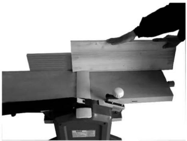
natural_image
Black-and-white photo of a hand operating a wooden machine with a ball on the handle (no text or symbols visible)
Attention
This manual does not replace professional training in working with planer machines.
13.3 Thicknesser
Connecting dust chute.
Slide the fence to right side and turn to 135^ . Remove the blade guard and place the dust chute. The dust chute is so positioned that both keys are in line with the longitude holes. Then push both keys into the longitude holes.
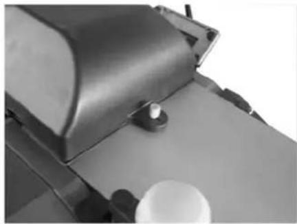
natural_image
Close-up of a mechanical device with a metallic top and a white circular component at the base (no visible text or symbols)- Adjust the desired height by means of the hand crank. A full rotation is 3mm height difference.
- When setting the inlet height, observe the maximum depth for cut of 1.5 mm.
- Always ensure low friction of the thickness planing table by using special lubrication oil for planing.
- Stuck workpieces may only be removed after the machine has been switched off and disconnected from the power supply.
• Workpieces that are too short should not be processed.

ACHTUNG
Always assemble the dust chute (planing or thick planing) and ensure that the keys are pushed (this press the safety switch!!)
14 MAINTENANCE

ATTENTION
Perform all maintenance machine settings with the machine being disconnected from the power supply! Serious injury due to unintentional or automatic activation of the machine!

The machine does not require extensive maintenance. If malfunctions and defects occur, let it be serviced by trained persons only.
Store the machine in a closed, dry location.
NOTICE
Clean your machine regularly after every usage – it prolongs the machines lifespan and is a pre-requisite for a safe working environment.
Repair jobs shall be performed by respectively trained professionals only!
14.1 Maintenance plan
| Inspections for the maintenance of the machine | |
| Loose or missing screws Daily before starting | |
| Damage to any part Daily before starting Daily before starting | |
| Clean the machine Daily before starting Daily before starting | |
| Inspection of blade Daily before starting | g |
| Cleaning of machine Dail | y after working |
After appro. 10 hours of operation we commend to lubricate the following parts: bearings of the feed-in and feed-out rollers, bearings of pulley and gear wheel of the belt. Check
14.2 Replacing blades
- Unplug the planer-thicknesser from power source and turn the switch to "off" position.
- -Block the blade guard from closing down.
- Loosen and remove three blade lock screws securing blade and blade clamp.
- -Lift blade and blade clamp from cutterhead.
- Clean any sawdust and resin buildup from cutterhead and blade clamp.
- Place blade clamp against the replacement blade and replace in cutterhead.
- -Secure blade and blade clamp using three blade lock screws. Do not over-tighten blade lock screws first.
Note: Check blade height at both of blade
- Tighten blade lock screws.
- Recheck blade adjustment and make sure blade is still level with outfeed table.
- Repeat the procedure to replace the other blade.
- Remove the scrap wood and release blade guard.
- Make sure all the blade lock screws are tight and snug.
NOTE:
- The blades which used with the tool may be replaced or re-sharpened.
- If the blades are re-sharpened, the re-sharpenings should be not more than 3 times with 0.05mm max. each time.
- -the blades used in this tool can not be used to rebate.
14.3 Storage
Never store the machine outdoors!
Storage permitted only at temperatures between +5° and +40° Celsius, at +40° Celsius the humidity must not be higher than 60%. Store in a dry and clean place.
14.4 Cleaning
After each workshift the machine has to be cleaned. Remove chips etc. with a suitable tool. Do not remove them by hand (cutting injury!). Remove dust as well.

NOTICE
The usage of certain solutions containing ingredients damaging metal surfaces as well as the use of scrubbing agents will damage the machine surface!
Clean the machine surface with a wet cloth soaked in a mild solution
14.5 Disposal
Do not dispose the machine in residual waste. Contact your local authorities for information regarding the available disposal options. When you buy at your local dealer for a replacement unit, the latter is obliged to exchange your old.

15 TROUBLE SHOOTING
Disconnect the machine from the power supply prior to any checks performed at the machine itself!
| Trouble Possible cause Solution | ||
| Machine does not start. | On-Switch not pushed | Check if ON-Switch is pushed |
| Damaged or incorrect connected extension cable | Check extension cable with other machine. | |
| Voltage supply (Voltage, frequency). | Power supply to the requirements of technical data operating voltage.This should be checked by an electrician and replaced if defective. | |
| Malfunction of ON/OFF switch | ||
| Material kickback | Cutting depth to high | Reduce cutting depth |
| Bad surface condition after operating | - Wrong adjust blade,- blunt blade | Exchange / re-adjust blade |
MANY MALFUNCTIONS AND DEFECTS CAN BE AVOIDED BY LETTING THE MACHINE BE CONNECTED TO YOUR POWER SUPPLY BY A CERTIFIED ELECTRICIAN.

NOTICE
Should you in necessary repairs not able to properly to perform or you have not the prescribed training for it always attract a workshop to fix the problem.
16 PREFACIO (ES)
iEstimado Cliente!
natural_image
Three industrial machine components shown in black-and-white photos: a hand holding a metal component, a machine with a handle, and a final machine with a cylindrical shaft (no visible text or symbols)Device to be operated in a perfect state only. Inspect the device visually every time it is to be used. Check in particular the safety equipment, electrical controls, electric cables and screwed connection for damage and if tightened properly. Replace any damaged parts before operating the device.
19.1 Operation instructions

ATENCIÓN
natural_image
Close-up of a hand holding a tool interacting with a black metal component, labeled 'C' (no text or symbols on the object itself)natural_image
Person using a machine tool on a wooden workbench, no visible text or symbols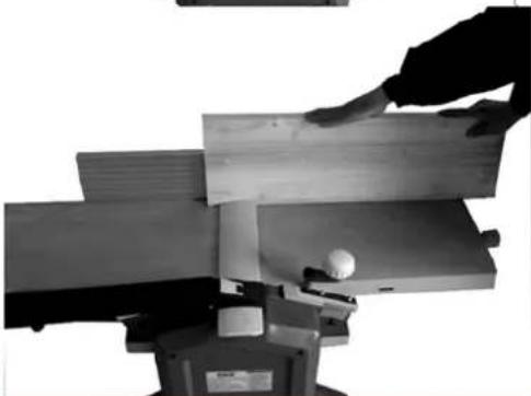
natural_image
Black-and-white photo of a hand operating a wooden machine with a ball on the tray (no visible text or symbols)
ATENCIÓN
natural_image
Close-up of a mechanical component with a metallic top and circular base, no visible text or symbolsnatural_image
Three-panel image showing a hand operating a metal bracket, a machine with a handle, and a machine with a cylindrical component (no visible text or symbols)Dust Collector must be connected, otherwise the machine will not start.
25.2 Dégauchisseuse
natural_image
Industrial machine with handle and control panel (no visible text or symbols)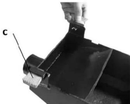
natural_image
Close-up of a mechanical component with a labeled section 'C' and a hand holding a tool (no readable text or symbols)natural_image
Person operating a machine tool on a workbench (no visible text or symbols)natural_image
Black-and-white photo of a hand operating a wooden machine with a ball on the workpiece (no visible text or symbols)Attention

natural_image
Close-up of a mechanical component with a metallic top and a white circular base (no visible text or symbols)AT-4707 Schlüsslberg
Tel 0043 (0) 7248 61116 - 700
Fax 0043 (0) 7248 61116 - 720
info@zipper-maschinen.at
29 BEZPEČNOST
natural_image
Close-up of a mechanical component with a hand holding a tool, labeled 'C' (no visible text or symbols)natural_image
Person operating a machine with tools and a ball on the workbench (no visible text or symbols)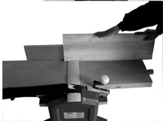
natural_image
Black-and-white photo of a hand operating a wooden machine with a ball on the workpiece (no visible text or symbols)
POZOR!
natural_image
Close-up of a mechanical component with a white spherical object on a surface (no visible text or symbols)natural_image
Close-up of a hand holding a tool interacting with a black metal component, labeled 'C' (no text or symbols on the object itself)natural_image
Person operating a workbench with tools and a ball on the machine (no visible text or symbols)Poravnavanje ozkih obdelovancev in robov desk
natural_image
Black-and-white photo of a hand operating a wooden cutting machine with a ball on the work (no visible text or symbols)
POZOR!
natural_image
Close-up of a mechanical device with a white spherical component and a metallic bracket (no visible text or symbols)natural_image
Close-up of a hand holding a metal bracket with a labeled point 'C' (no text or symbols on the object itself)U tu svrhu stol blanjalice B spustite u najniži položaj. Sada plastične spojnice C odsisnog adaptera povucite prema van. Pozicionirajte odsisni adapter i utisnite spojnice C u za to pre-viĐene utore A na izlaznom stolu za ravnanje.
Ravnanje tankih obradaka
natural_image
Person operating a workbench with tools and a ball on the table (no visible text or symbols)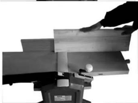
natural_image
Close-up of a hand operating a wooden cutting machine with a small white object on the workpiece (no visible text or symbols)
PAŽNJA!
natural_image
Close-up of a mechanical device with a metallic top and a white cup on the side (no visible text or symbols)| NO. | Description | Qty | NO. | Description | Qty | NO. | Description | Qty |
| 1 | Lock handle | 1 | 73 | 5-0.8X10mm Pan head screw | 4 | 139,2 | Nether cover | 1 |
| 2 | Lock block | 1 | 74 | Hex nut | 8 | 140 | Thread forming screw | 1 |
| 3 | 5-0.8X10mm Socket head screw | 4 | 75 | Pin | 1 | 141 | Terminal | 1 |
| 4 | Stop Block | 2 | 76 | Lock knob | 1 | 142 | Thread forming screw | 3 |
| 5 | 8-1.25X18mm Wing screw | 4 | 77 | Bridge guard support | 1 | 143 | Thread forming screw | 4 |
| 6 | 8mm Flat washer | 4 | 78 | Bridge guard | 1 | 144 | Overload protector | 1 |
| 7 | Rotating seat | 1 | 79 | Rivet | 1 | 145 | 5-0.8X10mm Socket head screw | 7 |
| 8 | 8-1.25mm Hex nut | 4 | 80 | Arm support | 1 | 146 | Rubber foot | 4 |
| 9 | 4-0.7mm Hex nut | 1 | 81 | 6X55mm Pin | 1 | 147 | 8mm Flat washer | 4 |
| 10 | 4-0.7X16mm Socket pan head screw | 1 | 82 | 6X55mm Pin | 1 | 148 | 8-1.25x16mm socket head screw | 4 |
| 11 | Fence | 1 | 83 | Link board | 1 | 149 | Rubber bushing | 1 |
| 12 | Support seat | 1 | 84 | 8mm Lock nut | 1 | 150 | Cord clamp | 6 |
| 13 | 6-1.0X16mm Socket head screw | 2 | 85 | Compression spring | 1 | 151 | 5-0.8X10mm Socket head screw | 6 |
| 14 | 6mm Flat washer | 2 | 86 | Link bar | 1 | 152 | Cord line | 1 |
| 15 | 5-0.8mm Hex nut | 1 | 87 | Support | 1 | 153 | Strain relief | 2 |
| 16 | 5-0.8X50mm Socket head screw | 1 | 88 | Screw | 1 | 154 | Rod | 4 |
| 17 | Support block | 1 | 89 | Compression spring | 1 | 155 | 1 | |
| 18 | 6-1.0X20mm Socket head screw | 2 | 90 | Lift knob | 1 | 155 | 4-0.7X8mm flat head screw | 1 |
| 19 | Outfeed table | 1 | 91 | Slide bar | 1 | 156 | Adjusting foam gasket | 1 |
| 20 | Crank cap | 1 | 92 | Compression spring | 1 | 157 | Nut | 1 |
| 21 | Crank handle | 1 | 93 | 12-1.75X10mm set screw | 1 | 158 | Compression spring | 1 |
| 22 | Crank shaft | 1 | 94 | Ratchet ahaft | 2 | 159 | Pushing rod | 1 |
| 23 | Jioning | 1 | 95 | Feed roller | 2 | 160 | Screw bushing | 1 |
| 24 | Plug | 1 | 96 | Bearing bush | 5 | 161 | Sleeve | 4 |
| 25 | Infeed table | 1 | 97,1 | Extension spring | 3 | 162 | Base | 1 |
| 26 | Working table clamping plate | 3 | 97,2 | Spring | 1 | 163 | 6-1.0x12mm Socket head screw | 2 |
| 27 | 6-1.0mm Acorn nut | 8 | 98 | Sheet metal deflector | 1 | 164 | 6mm Flat washer | 2 |
| 28 | Working table clamping plate | 1 | 99 | 6-1.0x10mm set screw | 4 | 165 | Motor assisting support | 1 |
| 29 | Cover | 2 | 100 | Adjusting stalk | 4 | 166 | Motor | 1 |
| 30 | 8-1.25mm Lock nut | 1 | 101 | Cutter head | 1 | 167 | V belt | 1 |
| 31 | 8mm Flat washer | 1 | 102 | Shaft | 1 | 168 | Motor pulley | 1 |
| 32 | Lift handle | 1 | 103,1 | 6001ZZ Ball bearing | 1 | 169 | 5-0.8X10mm Socket head screw | 4 |
| 33 | Flat washer | 2 | 103,2 | 6002ZZ Ball bearing | 1 | 170 | 5mm Lock washer | 4 |
| 34 | Strut | 1 | 104,1 | Bearing house | 1 | 171 | 5mm Flat washer | 4 |
| 35 | Pointer | 1 | 104,2 | Bearing house | 1 | 172 | 6mm Flat washer | 2 |
| 36 | 4mm Flat washer | 1 | 105 | Blade | 2 | 173 | 6-1.0X10mm Socket head screw | 2 |
| 37 | 4-0.7X10mm Pan head screw | 1 | 106 | Blade clamp | 2 | 174 | Sprocket | 4 |
| 38 | Rail | 1 | 107 | 6-1.0x16mm Socket pan head screw | 10 | 175 | 5mm Flat washer | 4 |
| 39 | Right support | 1 | 108 | Ratchet | 34 | 176 | 5-0.8mm Lock nut | 4 |
| 40 | 6mm Serrated washer | 8 | 109 | Spacer | 33 | 177 | Chain | 1 |
| 41 | 6-1.0x43mm Socket pan head screw | 8 | 110 | 3AMI-12 Retaining ring | 2 | 178 | Graphite | 3 |
| 42 | Spacer ring | 2 | 111 | Spacer ring | 1 | 179 | 6-1.0mm Hex nut | 1 |
| 43 | 5-0.8X6mm Set screw | 2 | 112 | 6-1.0X4mm Set screw | 2 | 180 | 6mm Lock washer | 1 |
| 44 | 5-0.8X12mm Socket head screw | 8 | 113 | Threaded spindle | 1 | 181 | 6mm Flat washer | 2 |
| 44,1 | 8 | 114 | Thicknessing table | 1 | 182 | Bushing | 1 | |
| 44,2 | 8 | 115 | Table cover plate | 1 | 183 | Tension sprocket | 1 | |
| 45,2 | Rail | 3 | 116 | Threaded spindle | 3 | 184 | Shaft | 1 |
| 46 | Right limiting plate | 2 | 117 | Chain | 1 | 185 | Protecting hood | 1 |
| 47 | Stop board | 1 | 118 | Wing,cpt. | 1 | 186 | Tool box | 1 |
| 48 | 6-1.0X10mm Socket head screw | 4 | 118,1 | Joint | 1 | 187 | Tool box cover | 1 |
| 49 | Left limiting plate | 2 | 118,2 | Supporting plate | 1 | 188 | 5-0.8mm acorn nut | 4 |
| 50 | Left support | 1 | 118,3 | Rivet | 1 | 189 | Switch | 1 |
| 51 | Max cutting guard | 1 | 119 | Needle bearing | 2 | 190 | Front side plate | 1 |
| 52 | 5-08x10mm Socket head screw | 4 | 120 | Bushing | 1 | 191 | 8-1.25x16mm socket head screw | 1 |
| 53 | 8-1.25X20mm Hex head bolt | 8 | 121 | Wheel | 1 | 192 | 8mm lock washer | 1 |
| 54 | 8mm Flat washer | 8 | 122 | 3AMI-10 Retaining ring | 1 | 193 | 8mm Flat washer | 1 |
| 55 | Spring pin | 8 | 123 | V belt | 1 | 194 | 8-1.25mm Hex nut | 4 |
| 56 | 5-0.8x16mm Socket head screw | 6 | 124 | Large sprocket | 2 | 195 | 5-0.8mm Hex nut | 1 |
| 57 | 5mm Lock washer | 6 | 125 | 6mm Flat washer | 2 | 196 | 5mm Flat washer | 1 |
| 58 | 8-1.25x12mm Socket head screw | 4 | 126 | 6-1.0X10mm Socket head screw | 2 | 197 | Pointer | 1 |
| 59 | 8mm Flat washer | 4 | 127 | 6-1.0x10mm set screw | 2 | 198 | 5-0.8x15mm Socket head screw | 1 |
| 61 | 4-0.7x28mm Socket head screw | 2 | 128 | Spindle pulley | 1 | 199 | Knob | 1 |
| 62 | Interlock switch | 1 | 129 | Eccentric shaft | 1 | 200 | Retaining ring | 1 |
| 63 | Switch cover | 1 | 130 | Extension spring | 1 | 201 | Dust collect | 1 |
| 64 | 5mm Flat washer | 4 | 131 | Gear | 1 | 202,1 | Thread forming screw | 6 |
| 65 | 5-0.8X8mm Socket head screw | 4 | 132 | Square sleeve | 1 | 203 | Dust collect cover | 1 |
| 66 | Back side plate | 1 | 133 | Small sprocket | 1 | 204 | Thread forming screw | 2 |
| 67 | 5-0.8X10mm Socket head screw | 7 | 134 | 8mm Flat washer | 1 | 205 | Dust collect key | 2 |
| 68 | Strain relief | 1 | 135 | 3AMI-9 Retaining ring | 1 | 206 | Wrench | 1 |
| 69 | Power cord | 1 | 136 | 5-0.8mm Hex nut | 1 | 207 | Push sticker | 1 |
| 70 | Insulator | 6 | 137 | 5-0.8x25mm Socket head screw | 1 | |||
| 71 | Quick connect terminals | 6 | 138 | Thread forming screw | 2 | |||
| 72 | Cable hook | 2 | 139,1 | Upper cover | 1 |
48 ERSATZTEILE / SPARE PARTS
With original ZIPPER spare parts you use parts that are attuned to each other shorten the installation time and elongate your machines lifespan.
IMPORTANT
The installation of other than original spare parts voids the warranty!
So you always have to use original spare parts
When you place a spare parts order please use the service formular you can find in the last chapter of this manual. Always take a note of the machine type, spare parts number and partname. We recommend to copy the spare parts diagram and mark the spare part you need.
You find the order address in the preface of this operation manual.
Company ZIPPER Maschinen GmbH grants for mechanical and electrical components a warranty period of 2 years for amateur use; and warranty period of 1 year for professional use, starting with the purchase of the final consumer. In case of defects during this period, which are not excluded by paragraph 3, ZIPPER will repair or replace the machine at its own discretion.
2.) Report:
In order to check the legitimacy of warranty claims, the final consumer must contact his dealer. The dealer has to report in written form the occurred defect to ZIPPER. If the warranty claim is legitimate, ZIPPER will pick up the defective machine from the dealer. Returned shippings by dealers which have not been coordinated with ZIPPER, will not be accepted and refused.
3.) Regulations:
a) Warranty claims will only be accepted, when a copy of the original invoice or cash voucher from the trading partner of ZIPPER is enclosed to the machine. The warranty claim expires if the accessories belonging to the machine are missing.
b) The warranty does not include free checking, maintenance, inspection or service works on the machine. Defects due to incorrect usage of the final consumer or his dealer will not be accepted as warranty claims either. Some examples: usage of wrong fuel, frost damages in water tanks, leaving fuel in the tank during the winter, etc.
c) Defects on wear parts are excluded, e.g. carbon brushes, collection bags, knives, cylinders, cutting blades, clutches, sealings, wheels, saw blades, splitting crosses, riving knives, riving knife extensions, hydraulic oils, oil/air/fuel filters, chains, spark plugs, sliding blocks, etc.
d) Also excluded are damages on the machine caused by incorrect or inappropriate usage, if it was used for a purpose which the machine is not supposed to, ignoring the user manual, force majeure, repairs or technical manipulations by not authorized workshops or by the customer himself, usage of non-original ZIPPER spare parts or accessories.
e) After inspection by our qualified personnel, resulted costs (like freight charges) and expenses for not legitimated warranty claims will be charged to the final customer or dealer.
f) In case of defective machines outside the warranty period, we will only repair after advance payment or dealer's invoice according to the cost estimate (incl. freight costs) of ZIPPER.
g) Warranty claims can only be granted for customers of an authorized ZIPPER dealer who directly purchased the machine from ZIPPER. These claims are not transferable in case of multiple sales of the machine.
4.) Claims for compensation and other liabilities:
The liability of company ZIPPER is limited to the value of goods in all cases. Claims for compensation because of poor performance, lacks, damages or loss of earnings due to defects during the warranty period will not be accepted. ZIPPER insists on its right to subsequent improvement of the machine.
52 GARANTÍA Y SERVICIO (ES)
1.) Garantía:
Product experience form
We observe the quality of our delivered products in the frame of a Quality Management policy.
Your opinion is essential for further product development and product choice. Please let us know about your:
- Impressions and suggestions for improvement.
- experiences that may be useful for other users and for product design
- Experiences with malfunctions that occur in specific operation modes
We would like to ask you to note down your experiences and observations and send them to us via FAX, E-Mail or b post:
Erworben von / purchased from:
E-Mail/ e-mail:
Please describe amongst others in the problem: What has cause the problem/defect, what was the last activity before you noticed the problem/defect? For electrical problems: Have you had checked you electric supply and the machine already by a certified electrician?
3. Bitte beachten
/ Additional information
INCOMPLETELY FILLED SERVICE FORMS CANNOT BE PROCESSED! FOR GUARANTEE CLAIMS PLEASE ADD A COPY OF YOUR ORIGINAL SALES / DELIVERY RECEIPT OTHERWISE IT CANNOT BE ACCEPTED. FOR SPARE PART ORDERS PLEASE ADD TO THIS SERVICE FORM A COPY OF THE RESPECTIVE EXPLODED DRAWING WITH THE REQUIRED SPARE PARTS BEING MARKED CLEARLY AND UNMISTAKABLE. THIS HELPS US TO IDENTIFY THE REQUIRED SPARE PARTS FASTLY AND ACCEL- LERATES THE HANDLING OF YOUR INQUIRY.