
ZIBRM52EST - Lawn mower Zipper - Free user manual and instructions
Find the device manual for free ZIBRM52EST Zipper in PDF.

| Product type | Petrol lawn mower with electronic starter |
| Brand | Zipper |
| Model | ZIBRM52EST |
| Engine type | Single cylinder 4 stroke |
| Engine power | 3.0 kW |
| Displacement | 173 cm³ |
| Fuel | Unleaded petrol (RON 95) |
| Fuel tank capacity | 0.8 L |
| Oil tank capacity | 0.6 L |
| Cutting width | 520 mm |
| Cutting height | 25 - 70 mm (7 levels) |
| Grass catcher volume | 60 L |
| Net weight | 40 kg |
| Gross weight | 44 kg |
| Starting | Electric (Li-Ion battery) and pull cord |
| Starter battery | Li-Ion 2000 mAh (28.8 Wh) |
| Charger | 110-240 V, 50/60 Hz, output 16 Wh |
| Sound pressure level | LPA 84 dB(A) (k=2.5 dB) |
| Guaranteed sound power level | LWA 98 dB(A) |
| Maximum vibrations | 4.301 m/s² (k=1.5 m/s²) |
| Functions | Grass collection, mulching, side discharge |
| Maintenance | Oil change, air filter, spark plug, blade |
| Operating temperature | +5 °C to +40 °C |
| Warranty | 2 years (non-commercial use), 1 year (commercial use) |
Frequently Asked Questions - ZIBRM52EST Zipper
User questions about ZIBRM52EST Zipper
0 question about this device. Answer the ones you know or ask your own.
Ask a new question about this device
Download the instructions for your Lawn mower in PDF format for free! Find your manual ZIBRM52EST - Zipper and take your electronic device back in hand. On this page are published all the documents necessary for the use of your device. ZIBRM52EST by Zipper.
USER MANUAL ZIBRM52EST Zipper
GASOLINE LAWN MOWER WITH E-START
FR MANUEL D'UTILISATION
natural_image
Green and black LiDAR lawn mower with attached ladder (no visible text or symbols)ZI-BRM52EST
EAN: 9120039233154
CE
ATTENTION: Check Oil
(15W40)!

1 INHALT / INDEX
1 INHALT / INDEX 2
15.1 Intended use of the machine....23
15.1.1 Technical Restrictions 23
15.1.2 Prohibited Use / Forseeable Misuse 23
15.2 User Qualification....23
15.3 Safety instructions 23
15.4 Special safety instructions for the operation 24
15.5 Safety instructions for machines with combustion engine....24
15.6 Safety instructions for using the charger 24
15.7 Safety Instructions AKKU / Battery 25
15.8 Hazard warnings 25
16 ASSEMBLY 26
16.1 Checking Delivery Content....26
16.2 Assembling the Machine....26
16.3 Checklist before Start-up....27
16.3.1 Checking/refilling engine oil 27
16.3.2 Checking fuel tank level / Refuelling Fuel Tank 28
17 OPERATION 28
17.1 Informationen on Initial Start-up 28
17.1.1 Test Run Initial Start-up.... 28
17.1.2 Notes for the first 20 operating hours 28
17.2 Operating instructions....29
17.2.1 Charging the battery for E-Start 29
17.3 Operating 29
17.3.1 Installing grass box 29
17.3.2 Adjusting cutting height 30
17.3.3 Starting the engine.... 30
With Recoil starter 30
With E-Start.... 30
17.3.4 Stopping the engine 30
17.3.5 Activating and de-activating the wheel drive.... 30
17.4 Changeover to different operating modes 31
17.4.1 Lawn mower 31
17.4.2 Mower with grass box 31
17.4.3 Mower for mulching.... 31
17.4.4 Mower with side discharge.... 31
18 MAINTENANCE 31
18.1 Maintenance and Servicing Plan 31
18.2 Changing the engine oil 32
18.3 Blade checking / changing 32
18.3.1 Checking the blade.... 32
18.3.2 Replacing the blade 32
18.4 Cleaning the air filter....32
18.5 Cleaning / replacing the spark plug....33
19 TRANSPORT 34
20 STORAGE 34
21 CLEANING 34
22 DISPOSAL 34
23 TROUBLESHOOTING 35
24 AVANT-PROPOS (FR) 36
25 SECURITE 37
natural_image
Close-up of a bicycle steering wheel with a downward arrow and green cable, labeled '1' (no text or symbols on the diagram itself)natural_image
Close-up of a black bicycle frame with a green handle and label '2' (no readable text or symbols)natural_image
Two views of a mechanical component with labeled parts (1, 2, 3), showing internal structure and hand holding part (no text or symbols present)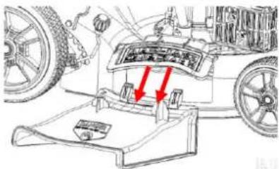
8 WARTUNG
WARNUNG

natural_image
Close-up of a mechanical component with no visible text or symbolsMotoröl wechseln:
natural_image
Mechanical component diagram showing a lever and pin assembly (no text or symbols)8.4 Luftfilter reinigen
HINWEIS

natural_image
Technical line drawing of a mechanical assembly (no visible text or symbols)
This manual contains information and important instructions for the installation and correct use of the ZIPPER gasoline lawn mower mit electro starter ZI-BRM52EST.
Following the usual commercial name of the machine (see cover) is substituted in this manual with the name "machine".

This manual is part of the product and shall not be stored separately from the product. Save it for later reference and if you let other people use the product, add this instruction manual to the product.
Please read and obey the security instructions!
Due to constant advancements in product design, construction pictures and content may diverse slightly. However, if you discover any errors, inform us please.
Technical specifications are subject to changes!
Please check the product contents immediately after receipt for any eventual transport damage or missing parts.
Claims from transport damage or missing parts must be placed immediately after initial product receipt and unpacking before putting the product into operation.
Please understand that later claims cannot be accepted anymore.
Copyright
© 2018
This document is protected by international copyright law. Any unauthorized duplication, translation or use of pictures, illustrations or text of this manual will be pursued by law.
Court of jurisdiction is the regional court Linz or the competent court for 4707 Schlüsslberg, Austria!
Customer service contact
This section contains information and important notices for safe commissioning and handling of machine.

For your own safety, read these operating instructions carefully before putting the machine into operation. This will enable you to handle the machine safely and prevent misunderstandings as well as possible damage to property and persons. Also observe the symbols and pictograms used as well as the safety instructions and hazard warnings!
15.1 Intended use of the machine
The machine is intended exclusively for the following activities:
For mowing and mulching lawns within the specified application limits.
ZIPPER-MASCHINEN assumes no responsibility or warranty for any other use or use beyond this and for any resulting damage to property or injury.
15.1.1 Technical Restrictions
The machine is intended for use under the following ambient conditions:
Relative humidity: max. 65 %
Temperature (for operation) +5°C bis +40°C
Temperature (for storage and/or transport) -20^ C bis +55^ C
15.1.2 Prohibited Use / Forseeable Misuse
• Operation of the machine without adequate physical and mental aptitude
- Operating the machine without appropriate knowledge of the operating instructions (machine + motor).
• Changes in the design of the machine
- Operating the machine in wet and rainy conditions
- Operating the machine in a potentially explosive environment
- Operating the machine indoors or in closed areas
• Operation of the machine without functioning or missing guards
- Remove the safety markings attached to the machine.
- Modify, circumvent or disable the safety devices of the machine.
- Use of the machine for the transport of persons
The prohibited/hazardous use or disregard of the information and instructions presented in this manual will result in the voiding of all warranty and damage claims against Zipper Maschinen GmbH.
15.2 User Qualification
Prerequisite for the use / operation of the machine is a corresponding physical and mental aptitude as well as knowledge and understanding of the instruction Manual.
Please note that local laws and regulations may determine the minimum age of the operator and restrict the use of this machine!
Put on your personal protective equipment before working on the machine.
Work on electrical components or equipment may only be carried out by a qualified electrician or carried out under the guidance and supervision of a qualified Electrician.
15.3 Safety instructions
In order to avoid malfunctions, damage and health hazards when working with this machine, in addition to the general rules for safe working, the following measures in particular must be observed UNCONDITIONALLY:
- Check that the machine is in perfect condition before each use. Ensure that all guards are in place and working properly and that all nuts, bolts, etc. are securely tightened. Do not take the machine into operation if you notice that parts are missing or damaged!
- Ensure sufficient lighting conditions in the working and surrounding areas of the machine.
- Keep hands and feet away from moving machine parts and always ensure a safe stand when working.
- Remove the adjustment tool from the machine before operation.
- Never leave the running machine unattended (always stop the machine before leaving it).
- Ensure that unauthorised persons maintain a safe distance from the machine and keep children away from the machine.
- The machine may only be operated, serviced or repaired by persons who are familiar with it and who have been informed of the dangers arising during this work.
• Always wear suitable personal protective equipment (ear protection, safety shoes etc.)! - Do not work with the machine if you are tired, not concentrated or under the influence of medication, alcohol or drugs!
- Never operate the unit in the presence of flammable liquids or gases (danger of explosion!).
- Carry out maintenance, adjustment and cleaning work only when the engine is switched off.
- Only use spare parts and accessories recommended by Zipper machines.
15.4 Special safety instructions for the operation
- The machine is designed to be operated by one person. Always operate the machine from behind. Never stand next to or in front of the machine when the engine is running.
- Excessive noise can cause hearing damage and temporary or permanent hearing loss. Wear hearing protection certified to health and safety regulations to limit noise exposure.
- Do not increase the regulated idle speed by your own. This could result in damage to the machine or personal injury.
15.5 Safety instructions for machines with combustion engine
- Do not touch the engine and/or muffler during operation or immediately after switching off! These areas become hot during operation and can cause burns.
• Do not touch the spark plug connector when the engine is running (electric shock!). - Do not operate the unit in closed areas or in poorly ventilated rooms unless there is adequate ventilation through exhaust fans or hoses. (Risk of suffocation from carbon monoxide!)
- Do not smoke while the machine is in operation.
- Do not smoke when refuelling the machine.
- Refuel the machine only in a well ventilated area.
• Do not refuel the machine when the engine is running or the machine is still hot. - Do not refuel the machine near naked flames.
- Do not spill fuel when refuelling.
- Do not crank a gas flooded engine as long as the spark plug is removed- fuel in the cylinder sprays out of the spark plug opening.
- Do not carry out an ignition spark test on engines if the engine is flooded or gas can be smelled. A stray spark could ignite the vapours.
- Do not use fuel to clean machine parts, especially indoors. Vapours from fuels may explode.
- Always keep the area around the muffler free of foreign substances such as leaves, paper, cardboard, etc. A hot muffler could ignite these substances and cause a fire.
- Close the filler cap after refuelling.
- Check the fuel line and tank regularly for leaks and cracks. Do not operate the machine if leaks in the fuel system are known.
- Store fuel only in designated and approved containers.
15.6 Safety instructions for using the charger
- The battery charger is only suitable for charging the machine's battery that is supplied. Charging other batteries is not permitted.
- Never use the charger in a damp or wet environment.
- Only disconnect cable connections by pulling the plug. Pulling on the cable could damage the cable and plug and electrical safety would no longer be guaranteed.
- Never use the charger if the cable, plug or the device itself is damaged by external influences. Then take the charger to the nearest specialist workshop.
- Do not operate the appliance near heat sources.
• Never open the charger. In the event of a fault, contact a specialist workshop. - Only use the original charger to charge the battery. Using other chargers may cause defects or cause a fire.
15.7 Safety Instructions AKKU / Battery
- Vapours may escape if used improperly or if the batteries are damaged. Supply fresh air and consult a doctor if you have any complaints. The vapours may irritate the respiratory tract.
- DANGER OF FIRE! Never charge batteries in the vicinity of acids and highly flammable materials.
- Only charge the battery in an ambient temperature between 0°C and +40°C. Allow the battery to cool down after heavy charging.
- DANGER OF EXPLOSION! Protect battery from heat and fire.
• Only use the battery in an ambient temperature between 0^ C and +45^ C. - DANGER OF SHORT CIRCUIT! For disposal, transport or storage the battery must be packed (plastic bag, box) or the contacts must be taped.
- Never open the battery
15.8 Hazard warnings
Despite intended use, certain residual risks remain.
Remaining risks:
- Risk of injury due to noise:
Working for a long time can damage your hearing if you do not have a very good hearing protection.
- Risk of injury due to the working area:
Solid objects, stones, metal parts, or the like can be thrown out!
- Risk to the hands or fingers:
Do not grab in the cutting tool while it is rotating.
- Risk of injury due to pick up and roll up:
Wires and cords can be detected by the cutting tool and can damage the machine and can cause injuries. Unplug battery and safety switch (if equipped) before removing the deposits!
- Risk of injury due to vibration:
The declared vibration emission value has been for a standardized test is measured and can be used to compare one tool with another electric are.
The declared vibration emission value may also be used for a preliminary assessment of exposure. Warning: Emission level of vibration can be different from the specified value during the actual use of the electric tool, depending on the manner in which the power tool is used. When you feel uncomfortable or notice discoloration of skin on your hands during the use of the machine, stop working immediately. Observe sufficient break times to rest. Failure to have sufficient break times may result in a hand-arm vibration syndrome.
The extent of exposure depending on the type of work or machine use should be estimated and appropriate breaks taken. In this way, the extent of exposure can be considerably reduced over the entire work time. Minimize the risk caused by vibrations. Maintain this machine according to the instructions in the manual.
- Rotating parts
Be rotating parts (blades) mounted incorrectly, this can lead to serious accidents.
Check before starting work, the cutting blade for tight fit
- Risk of burns:
Touching the mufflers, exhaust and other machine components which can be hot after prolonged continuous operation or when the engine is hot cause severe burns.
- Risk of fire and explosion:
Gasoline is highly flammable and explosive under certain conditions.
NEVER refuel fuel or engine oil while the machine is in operation or is hot.
When refueling and at places where fuel is stored not smoke or allow open flames or sparks.
Do not overfill the fuel tank and avoid the spillage of gasoline during refueling. If fuel is spilled make sure the area is completely dry and cleaned before starting the engine.
Make sure that the filler cap is tightly closed again after refueling safely.
• Chemical risks:
Never use or refuel a gasoline or diesel engine in a closed area without adequate ventilation.
Carbon monoxide emissions from the internal drive units of the engine can cause in confined spaces through inhalation health effects and death. Therefore use the machine only in well-ventilated rooms or outdoors in operation.
Liquid fuels can cause serious damage on the skin and the environment.
These risk factors can be minimized through obeying all security and operation instructions, proper machine maintenance, proficient and appropriate operation by persons with technical knowledge and experience
Due to the design and construction of the machine, hazardous situations may occur which are identified as follows in these operating instructions:
DANGER

A safety instruction designed in this way indicates an imminently hazardous situation which, if not avoided, will result in death or serious injury.
WARNING

Such a safety instruction indicates a potentially hazardous situation which, if not avoided, may result in serious injury or even death.
CAUTION

A safety instruction designed in this way indicates a potentially hazardous situation which, if not avoided, may result in minor or moderate injury.
NOTICE

A safety note designed in this way indicates a potentially dangerous situation which, if not avoided, may result in property damage.
Irrespective of all safety regulations, their sound common sense and corresponding technical suitability/training are and remain the most important safety factor in the error-free operation of the machine. Safe working depends first and foremost on you!
16 ASSEMBLY
16.1 Checking Delivery Content
Check the machine immediately after delivery for transport damage and missing parts.
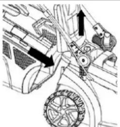
16.2 Assembling the Machine
The machine comes pre-assembled, only the parts dismantled for transport have to be reassembled.
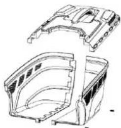
natural_image
Technical line drawing of a mechanical housing assembly (no text or symbols)Assemble the parts together an fix them with the 2 screws at the base of the grass box
 | Pull up the lower handle and fix the handle with the lower handle clamp. | ||
 | Install the upper handle clamp.Turn the clamping loose by hand and then close lever for fixing. | ||
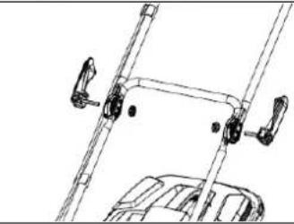 | Fix the upper handle with the upper handle clamp. | ||
 | When unfold the mower avoid pinching or trapping any cables! | ||
16.3 Checklist before Start-up
NOTICE

The use of paint thinners, petrol, aggressive chemicals or abrasives leads to material damage to the surfaces! Therefore use only mild detergents for cleaning!
- Clean the machine and remove dirt and grass if necessary.
- If the air filter is dirty, blow the filter cartridge from the inside by moving a jet of dry compressed air up and down. Continue until all dust has been removed. Replace the air filter with a new one if necessary.
- Check the carburettor for external dirt and dust and clean it with dry compressed air if necessary.
- Check the nuts and bolts for tightness, paying particular attention to the knife. (Screws or bolts loosened by vibrations can lead to accidents)
16.3.1 Checking/refilling engine oil
NOTICE

Too low an oil level will damage the engine and shorten the life of the machine. Therefore, check the engine oil level before each start and top up if necessary.
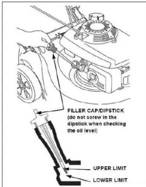
- To check the engine oil level, place the machine on a safe, level surface. Switch off the engine and allow the machine to stand for ten minutes so that the circulating oil can collect in the oil pan.
- Unscrew the oil dipstick and wipe it with a clean, lint-free cloth or a non-fibrous paper towel.
- Push the measuring rod back into the opening as far as it will go, but do not screw it in. (Make sure that the rod has really been pushed in completely - sometimes it cants itself).
- Pull out the oil dipstick again and read off the oil level. There are two markings for this - see illustration on the left.
- If the oil level is low, top up recommended oil to the upper limit (maximum filling volume according to technical data).
- Insert the oil dipstick again and tighten it.
16.3.2 Checking fuel tank level / Refuelling Fuel Tank
NOTICE

Observe the safety regulations for fuel control. Filter the fuel during refuelling to prevent foreign particles from entering the combustion chamber. Wipe up leaked fuel.
Process:
- Screw on the tank cap (sits on the fuel tank).
- Level check in the form of a visual inspection. If necessary, top up petrol with the appropriate octane number (RON 95) (maximum tank volume according to technical data).
- Close the filler cap tightly after refuelling.
17 OPERATION
Only put the machine into operation after you have read and understood the safety instructions and carried out the necessary measures before initial commissioning..
17.1 Informationen on Initial Start-up
NOTICE

The machine is delivered without engine oil and fuel. Make sure that this equipment is filled up before the machine is put into operation for the first time.
17.1.1 Test Run Initial Start-up
- Let the machine run idle for about 3 minutes.
- Watch out for abnormal noises.
- Pay attention to the exhaust fumes (too black, too white)?
17.1.2 Notes for the first 20 operating hours
In order to optimize the life expectancy of your machine, the following points should be observed:
- Spare the engine for the first 20 operating hours (this also applies to used engines after extensive maintenance). This means lower speed and lower maximum working load than during normal operation.
- Change the engine oil after the first 20 hours of operation.
17.2 Operating instructions
• Never tighten the cable while the engine is running. This will damage the motor.
- The pull mechanism for changing the motor speed is limited by an adjusting screw. This is factory set. Never change this setting on your own, you could overload the motor.
- Under no circumstances should you operate the machine on slopes of more than 20°, as even with an optimum oil level the engine may not be supplied with sufficient lubrication.
- In the direction of the forward movement of the machine and within a range of one meter around the machine, nobody but the operator must stand.
• Pay particular attention to the following particularly dangerous areas:
- Special precautions must be taken when mowing on slopes. Only mow crosswise to the slope, never downwards or upwards, observing the maximum permissible slope angle.
- The cutting height can be adjusted by means of a lever on the machine, adjust it to the respective condition of the lawn to be worked.
17.2.1 Charging the battery for E-Start
 | Open the rear discharge door.Lift the grass box by its handle and place under the rear door, so that the hooks on the grass box frame are seated into the slots provided in the handle bracket. . Release the rear door. When installed correctly, the grass box will fit snugly against the rear of the mower and the rear discharge door will fit into the recess in the top of the grass box. | |
 | Indicator grass box:The grass box has an indicator on the side of the box.If the indicator is lifted when mowing the grass box is empty.If the indicator is closed the grass box must be emptied. |
17.3.2 Adjusting cutting height
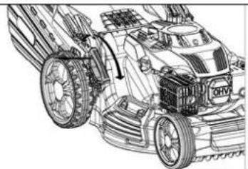
natural_image
Technical line drawing of a tractor's wheel assembly and engine components (no text or symbols)The cutting height is set centrally with one lever
- Pull the cutting height lever sideways
- Push the lever in desired positon and allow the lever to engage into one of the slots
Lower position: 25mm
Upper position: 70mm
17.3.3 Starting the engine
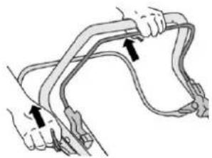
natural_image
Illustration of two hands tying a rope knot (no text or symbols)With Recoil starter
- Pull the engine lever against the push handle.
• Pull out the starter handle briskly - Guide the starter-handle slowly to the rope guide back as soon as the engine starts.
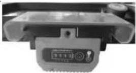
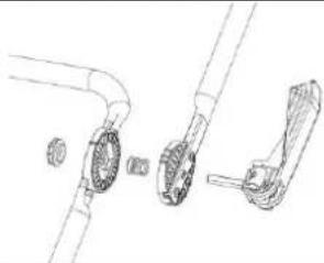
natural_image
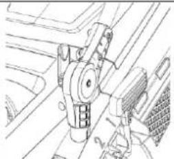
Close-up of a mechanical component with a button and indicator lights (no visible text or symbols)With E-Start
- Opening the battery drawer
- Place the charged battery on the insertion grooves and push it in until the battery clicks into place
- Closing the battery drawer
- Pull the engine start bracket to the handle
- Press E-start button until engine starts
- Release the E-start button when the engine is running
17.3.4 Stopping the engine
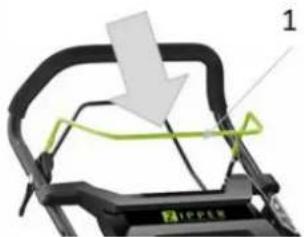
natural_image
Close-up of a mechanical device with a white arrow pointing to a green line and labeled component '1' (no readable text or symbols beyond labels)- Release the engine lever to stop the engine and the blades
17.3.5 Activating and de-activating the wheel drive

natural_image
Close-up of a black bicycle steering wheel with green guide railings and a yellow cable, labeled with number 2 (no text or symbols on the diagram itself)Wheel drive activating
- Press the drive lever to the push handle and the mower will move forward when the engine is running.
Wheel drive de-activating
17.4 Changeover to different operating modes
This lawnmower can be modified to 4 operating modes:
- lawn mower
- lawn mower with grass catcher
- a mulch mower or to
- a lawn mower with side discharge
17.4.1 Lawn mower
Use the mower without a collection basket and the lawn is not collected but left on the mowing area.
17.4.2 Mower with grass box
Use the lawn mower with grass box and the lawn is collected in the grass box. The mulching block and side discharge lateral ejection must be removed.
17.4.3 Mower for mulching
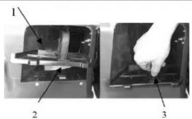
natural_image
Two views of a mechanical device with labeled parts, showing internal components and a hand inserting a component (no text or symbols visible)ft the rear discharge door and remove the grass box. sert the mulching plug into the opening. ose the rear discharge door.
What is mulching?
When mulching the grass or foliage is cut in one step, then fine chopped and then ejected as a natural fertilizer again.
Tips to mulch mowing:
- Regular pruning to max. 2 cm (from 6 cm to 4 cm tall grass)
• The blades should be as sharp - Mow wet grass
- Move the mower at a walking pace
• Regularly clean the mulching plug, the housing interior and the mower blade
17.4.4 Mower with side discharge
- Lift the rear discharge door and remove the grass box.
- Mount the mulching plug
- Lift the cover for side discharge.
• Install the side ejection guide to the holder of the flap. - Lower the cover - the side discharge will be fixed by the cover
- Seitenklappe senken – die Klappe fixiert nun auf den Seitenauswurf
18 MAINTENANCE
WARNING

Hot surfaces and rotating machine parts while the engine is running can cause serious injury or even death. Always stop the machine before carrying out any conversion, adjustment, cleaning or maintenance work, let it cool down and secure it against unintentional restarting.
18.1 Maintenance and Servicing Plan
What to do?
frequency
| Check fuel level | before each start-up |
| Check engine oil level | before each start-up |
| Control of the operating elements | before each start-up |
| Check for damaged parts | before each start-up |
| Checking for loose or lost screws | before each start-up |
| Change engine oil | First after 5h or 1 month, then every 3 months or 25h |
| Air filter cleaning/replacement | every 25h or 3 months |
| Spark plug test/replacement | every 200 h or 2 years |
| Fuelfilter cleaning | every 25h or 3 months |
The specified intervals refer to working under "normal" operating conditions. Depending on the load, a change/exchange may also be necessary at an earlier point in time.
18.2 Changing the engine oil
NOTICE


Engine oil is toxic and must not be released into the environment. When changing, use suitable collecting containers with sufficient volume! Observe the manufacturer's instructions and, if necessary, contact your local authorities for further information regarding proper disposal.
Oil drain screw
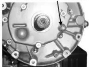
natural_image
Close-up of a mechanical component with no visible text or symbolsChange engine oil:
- drain the used oil while the engine is warm. Warm oil drains quickly and completely.
- wipe the oil filling area clean and then remove the oil drain screw.
- Fill with the recommended oil. Do not overfill! Wait a few minutes for the oil to settle in the engine and only then measure the oil level.
18.3 Blade checking / changing
NOTICE

After assembly, check that the blade screws are firmly tightened. Always wear protective gloves when working on the blade.
18.3.1 Checking the blade
- Tilt the mower to the right with the air filter side facing up. This helps to avoid fuel leaks and hard starting.
- Check the blade for damage, cracks and excessive rust or corrosion: a blunt blade can be sharpened, but a blade that is excessively worn, bent, cracked or otherwise damaged must be replaced.
18.3.2 Replacing the blade
- Remove the screw with a socket wrench. Use a wooden block to prevent the blade from turning when the bolt is removed. Then remove the blade.
- Mount the blade with the screw and special washers. Be sure to mount the special washers with the concave side facing the blade and the convex side facing the bolt.
- Tighten the screw with a torque wrench. Use a wooden block to prevent the blade from turning when the screw is tightened.
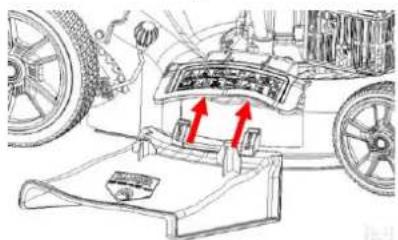
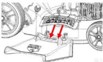
18.4 Cleaning the air filter
NOTICE

natural_image
Mechanical component diagram showing a lever and pin assembly (no text or symbols)
If the engine is operated with or without a damaged air filter, dirt will get into the engine, resulting in rapid engine wear.
natural_image
Technical line drawing of a mechanical assembly (no visible text or symbols)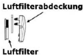
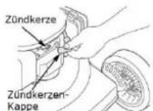
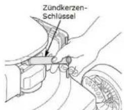
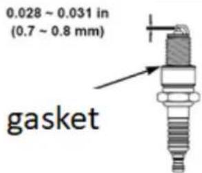
18.5 Cleaning / replacing the spark plug
NOTICE

A loose spark plug can overheat and damage the engine. Tightening the spark plug too much can damage the thread in the cylinder head.
For error-free operation, the contact surface of the candle in the cylinder head and the sealing ring of the candle must be clean and free of residues.
-
Take off the spark plug cap and remove any dirt underneath.
-
Remove the spark plug with a spark plug wrench.
-
Check the spark plug. Replace it if the electrodes are worn out or if the insulator is torn or broken.
-
Measure the electrode gap of the spark plug with a suitable measuring device. The distance should be 0.7 - 0.8 mm. If necessary, correct the gap by carefully bending the side electrode with a suitable tool.
-
Fit the spark plug cap.
19 TRANSPORT
WARNING

Never lift or transport the machine with the engine running!
Secure the machine in its position (tying up, jamming the wheels)
Empty fuel tank completely to avoid fuel leakage
20 STORAGE
- To reduce the risk of fire, keep the engine, silencer, battery compartment and fuel tank free of grass, leaves or excessive grease.
- Allow the product to cool for at least 30 minutes before storage.
• Before storage, clean the mower thoroughly and store it in a dry, frost-free place. - Never store the mower with fuel in the tank inside a building where it can reach an open flame or spark.
• If the fuel tank needs to be emptied, this should be done outdoors.
If the machine is not used for a longer period of time (>30 days):
• Empty the oil or fuel tank.
- Remove the spark plug and pour a few drops of engine oil into the cylinder. Using a rope starter, turn the engine a few times so that the oil is well distributed inside the cylinder. (Clean spark plug before reuse!)
21 CLEANING
NOTICE

Incorrect cleaning agents can attack the paint on the machine. Do not use solvents, nitro thinner or other cleaning agents that could damage the machine's paint.
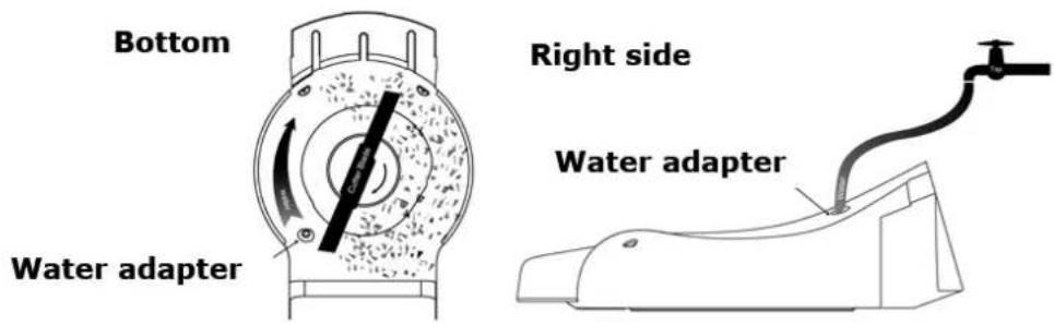
Regular cleaning is also a basic rule for the safe operation of the machine and a long lifetime of the machine. Once every season, the drive wheels should be cleaned internally. Remove both wheels. Clean the gear wheel and the wheel gear rim of grass and dirt using a brush or compressed air.
If the machine is stored for longer than 30 days:
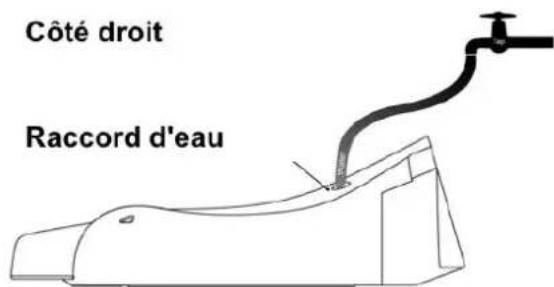
Connect a water hose to the water adapter and let the machine run for a short time.
Do not tilt the mower!
22 DISPOSAL
Do not dispose of your machine in residual waste. Contact your local authorities for information on available disposal options. If you buy a new vibratory plate or equivalent from your dealer, he is obliged in certain countries to dispose of your old machine properly.
23 TROUBLESHOOTING
WARNING

Hot surfaces and rotating machine parts while the engine is running can cause serious injury or even death. Switch off the machine before carrying out any troubleshooting work and secure it against unintentional restarting.
| failure | Possible cause | Repair |
| Engine does not start | Incorrect starting sequence | Observe the correct starting sequence |
| Dirty air filter | Clean/replace air filter | |
| No fuel supply | Refuel | |
| Fault in the fuel line | Check the fuel line for kinks or damages | |
| Engine flooded. | Screw off, clean and dry the spark plug. Then pull the cranking rope several times and reinstall the spark plug | |
| Spark plug connector not placed on. | Place on the spark plug connector | |
| No ignition spark | Clean/replace spark plugCheck ignition cable | |
| Engine does not start at E-start | No/low battery | Insert/charge battery |
| Engine starts and is stalled immediately | Incorrect idle adjustment | Contact customer service |
| Machine works with interruptions | Carburetor incorrectly adjusted | Contact customer service |
| Spark plug fouled | Clean/replace spark plugCheck spark plug connector | |
| Smoke | Incorrect fuel | Use correct fuel |
| Carburetor incorrectly adjusted | Contact customer service | |
| Machine does not work with full performance | Machine overloaded | Grass too tough |
| Dirty air filter | Clean/replace air filter | |
| Carburetor incorrectly adjusted | Contact customer service | |
| Rough running, vibrations | Loose blade screw | Tighten blade screw |
| Damaged or unbalanced blade | Balance or replace blade | |
| Low quality cut | Foreign material/grass wrapped, around the blade | Remove Foreign material/grass |
| To high grass | Set to correct cutting height | |
| Poor pickup of the grass | Wrong cutting height | Set to correct cutting height |
| Blade worn | Replace blade | |
| Full grass box | Empty grass box |
24 AVANT-PROPOS (FR)
Cher client, chère cliente,
25.1.1 Restrictions techniques
Contacter le service client
natural_image
Technical line drawing of a vehicle's wheel assembly with arrows indicating components (no text or symbols)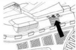
natural_image
Architectural floor plan showing building layout and a black arrow pointing to a specific area (no text or symbols present)natural_image
Technical line drawing of a tractor's front wheel assembly (no text or symbols)natural_image
Illustration of hands using a cable to lift a car (no text or symbols present)natural_image
Close-up of a mechanical component with a control panel and circular dial (no visible text or symbols)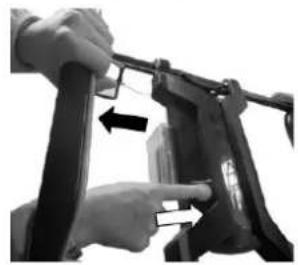
natural_image
Close-up of hands installing or adjusting a mechanical device with a black arrow pointing to the component (no visible text or symbols)natural_image
Mechanical component diagram showing a frame with a handle and green cable, labeled with number 2 (no text or symbols on the diagram itself)natural_image
Two views of a mechanical component with labeled parts, showing internal structure and hand holding part (no text or symbols visible)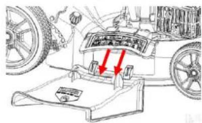
28 MAINTENANCE
AVERTISSEMENT

natural_image
Mechanical component diagram showing a bolted joint with a central shaft and base (no text or symbols)natural_image
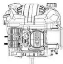
Technical line drawing of an internal combustion engine (no text or symbols visible)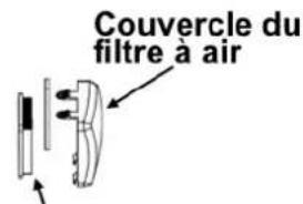
(EN) With original ZIPPER spare parts you use parts that are attuned to each other shorten the installation time and elongate your machines lifespan.
IMP OR TAN T
The installation of other than original spare parts voids the warranty!
So you always have to use original spare parts
When you place a spare parts order please use the service form you can find in the last chapter of this manual. Always take a note of the machine type, spare parts number and part name. We recommend to copy the spare parts diagram and mark the spare part you need.
You find the order address in the preface of this operation manual.
| Nr. | Name | Qty. | Nr. | Name | Qty. |
| 1 | upper handrail | 1 | 57 | selfpropelled ratchet washer | 4 |
| 2 | lower handrail | 1 | 58 | Ratchet Wheel R | 1 |
| 3 | stop lever | 1 | 59 | spring washer | 6 |
| 4 | Self-propelled Lever | 1 | 60 | Ratchet Wheel L | 1 |
| 5 | foam pipe | 1 | 61 | Brake spring | 1 |
| 6 | lever guard | 1 | 62 | selfpropelled spring | 1 |
| 7 | Hexagon head bolts | 2 | 63 | front drive assy | 1 |
| 8 | Self-locking nut | 2 | 64 | inner cover of hub | 2 |
| 9 | Rope Guide | 1 | 65 | wheel assy | 2 |
| 10 | cap nut | 1 | 66 | outer cover of hub | 2 |
| 11 | Brake Cable Assy plate | 1 | 67 | front drive spring | 2 |
| 12 | selfpropelled cable | 1 | 68 | Height Adjustment Pull Rod | 1 |
| 13 | brake cable | 1 | 69 | blocked plate | 2 |
| 14 | quick fix knob | 2 | 70 | front face mask | 1 |
| 15 | quick fix handle | 2 | 71 | front face screwing | 1 |
| 16 | lever pin | 2 | 72 | grass board | 1 |
| 17 | open ring | 2 | 73 | front face plate cover | 1 |
| 18 | big flat washer | 2 | 74 | aluminum low bracket-left | 1 |
| 19 | flat washer | 2 | 75 | aluminum low bracket-right | 1 |
| 20 | small triangle knob | 2 | 76 | cable stopper | 1 |
| 21 | Hex nut | 2 | 77 | O ring | 1 |
| 22 | Hexagon head bolts | 2 | 78 | inlet | |
| 23 | hex self-locking nut | 2 | 79 | outlet | 1 |
| 24 | Hexagon head bolts | 2 | 80 | Half round head square neck bolts | 4 |
| 25 | aluminum bracket-upper | 2 | 81 | deck | 1 |
| 26 | conical spring washer | 2 | 82 | Bracket plate for defelctor | 1 |
| 27 | rotating shaft for quicklever | 2 | 83 | Cross recessed Pan head tapping | 2 |
| 28 | aluminium quick lever | 2 | 84 | Mulch Shaft | 1 |
| 29 | fastener | 1 | 85 | mulch board spring | 1 |
| 30 | rear baffle | 1 | 86 | mulching board | 1 |
| 31 | rear baffle window | 1 | 87 | side discharge cover | 1 |
| 32 | Pan head self-tapping screws | 18 | 88 | V belt | 1 |
| 33 | rear discharge cover | 1 | 89 | front drive right bracket | 1 |
| 34 | Shaft for rear discharge cover | 1 | 90 | front drive left bracket | 1 |
| 35 | rear discharge cover spring -R L | 1 | 91 | Half round head square neck bolts | 4 |
| 36 | rear discharge cover spring -L | 1 | 92 | rear drive bracket | 2 |
| 37 | the base of rear discharge cover | 1 | 93 | belt cover | 1 |
| 38 | Pan head tapping screws | 8 | 94 | square washer | 2 |
| 39 | mulching plug | 1 | 95 | double-head bolt | 2 |
| 40 | rubber dust proof board | 1 | 96 | hex tapping screws | 1 |
| 41 | dust proof board fis shaft | 1 | 97 | blade adapter | 1 |
| 42 | R type pin | 2 | 98 | blade | 1 |
| 43 | rear drive assy | 1 | 99 | blade washer | 1 |
| 44 | height adjustment handle | 1 | 100 | bolt of blade | 1 |
| 45 | cover height adjustment handle | 1 | 101 | top of grass box | 1 |
| 46 | hex self-locking nut | 2 | 102 | air-out board of fabric grass bag | 1 |
| 47 | hex bolt | 2 | 103 | top grass box screwing | 1 |
| 48 | big washer | 2 | 104 | lower of grass box - right | 1 |
| 49 | wave form washer | 4 | 105 | lower of grass box - left | 1 |
| 50 | inner cover of hub | 2 | 106 | grass sticker board | 2 |
| 51 | wheel assy | 2 | 107 | plum flowe self-tapping screws | 6 |
| 52 | hex self-locking nut | 14 | 108 | T575 Engine | 1 |
| 53 | outer cover of hub | 2 | 109 | big washer | 2 |
| 54 | selfpropelled assy. | 1 | 110 | flat washer | 2 |
| 55 | Ratchet Wheel pin | 2 | 111 | control panel upper | 1 |
| 56 | rear wheel axle sleeve | 2 | 1 |
36 GARANTIE (DE)
1.) Garantie :
Company ZIPPER Maschinen GmbH grants for mechanical and electrical components a warranty period of 2 years for amateur use; and warranty period of 1 year for professional use, starting with the purchase of the final consumer. In case of defects during this period, which are not excluded by paragraph 3, ZIPPER will repair or replace the machine at its own discretion.
2.) Report :
In order to check the legitimacy of warranty claims, the final consumer must contact his dealer. The dealer has to report in written form the occurred defect to ZIPPER. If the warranty claim is legitimate, ZIPPER will pick up the defective machine from the dealer. Returned shippings by dealers which have not been coordinated with ZIPPER, will not be accepted and refused.
3.) Regulations :
a) Warranty claims will only be accepted, when a copy of the original invoice or cash voucher from the trading partner of ZIPPER is enclosed to the machine. The warranty claim expires if the accessories belonging to the machine are missing.
b) The warranty does not include free checking, maintenance, inspection or service works on the machine. Defects due to incorrect usage of the final consumer or his dealer will not be accepted as warranty claims either. Some examples : usage of wrong fuel, frost damages in water tanks, leaving fuel in the tank during the winter, etc.
c) Defects on wear parts are excluded, e.g. carbon brushes, collection bags, knives, cylinders, cutting blades, clutches, sealings, wheels, saw blades, splitting crosses, riving knives, riving knife extensions, hydraulic oils, oil/air/fuel filters, chains, spark plugs, sliding blocks, etc.
d) Also excluded are damages on the machine caused by incorrect or inappropriate usage, if it was used for a purpose which the machine is not supposed to, ignoring the user manual, force majeure, repairs or technical manipulations by not authorized workshops or by the customer himself, usage of non-original ZIPPER spare parts or accessories.
e) After inspection by our qualified personnel, resulted costs (like freight charges) and expenses for not legitimated warranty claims will be charged to the final customer or dealer.
f) In case of defective machines outside the warranty period, we will only repair after advance payment or dealer's invoice according to the cost estimate (incl. freight costs) of ZIPPER.
g) Warranty claims can only be granted for customers of an authorized ZIPPER dealer who directly purchased the machine from ZIPPER. These claims are not transferable in case of multiple sales of the machine.
4.) Claims for compensation and other liabilities :
The liability of company ZIPPER is limited to the value of goods in all cases. Claims for compensation because of poor performance, lacks, damages or loss of earnings due to defects during the warranty period will not be accepted. ZIPPER insists on its right to subsequent improvement of the machine.
38 GARANTIE (FR)
1.) Garantie :
We monitor the quality of our delivered products in the frame of a Quality Management policy.
Your opinion is essential for further product development and product choice. Please let us know about your:
- Impressions and suggestions for improvement.
- experiences that may be useful for other users and for product design
- Experiences with malfunctions that occur in specific operation modes
We would like to ask you to note down your experiences and observations and send them to us via FAX, E-Mail or by post
Erworben von / purchased from:
E-Mail/ e-mail:
Please describe amongst others in the problem: What has cause the problem/defect, what was the last activity before you noticed the problem/defect? For electrical problems: Have you had checked you electric supply and the machine already by a certified electrician?
3. Bitte beachten
/ Additional information
INCOMPLETELY FILLED SERVICE FORMS CANNOT BE PROCESSED! FOR GUARANTEE CLAIMS PLEASE ADD A COPY OF YOUR ORIGINAL SALES / DELIVERY RECEIPT OTHERWISE IT CANNOT BE ACCEPTED. FOR SPARE PART ORDERS PLEASE ADD TO THIS SERVICE FORM A COPY OF THE RESPECTIVE EXPLODED DRAWING WITH THE REQUIRED SPARE PARTS BEING MARKED CLEARLY AND UNMISTAKABLE. THIS HELPS US TO IDENTIFY THE REQUIRED SPARE PARTS FASTLY AND ACCEL- LERATES THE HANDLING OF YOUR INQUIRY.


- ZI-BRM52EST
- INHALT / INDEX
- INHALT / INDEX 2
- ASSEMBLY 26
- OPERATION 28
- WARTUNG
- WARNUNG
- Luftfilter reinigen
- HINWEIS
- Please read and obey the security instructions!
- Copyright
- Customer service contact
- Intended use of the machine
- Technical Restrictions
- Prohibited Use / Forseeable Misuse
- User Qualification
- Safety instructions
- Special safety instructions for the operation
- Safety instructions for machines with combustion engine
- Safety instructions for using the charger
- Safety Instructions AKKU / Battery
- Hazard warnings
- DANGER
- WARNING
- CAUTION
- NOTICE
- ASSEMBLY
- Checking Delivery Content
- Assembling the Machine
- Checklist before Start-up
- Checking/refilling engine oil
- Checking fuel tank level / Refuelling Fuel Tank
- Process:
- OPERATION
- Informationen on Initial Start-up
- Test Run Initial Start-up
- Notes for the first 20 operating hours
- Operating instructions
- Charging the battery for E-Start
- Adjusting cutting height
- Starting the engine
- With Recoil starter
- With E-Start
- Stopping the engine
- Activating and de-activating the wheel drive
- Wheel drive activating
- Wheel drive de-activating
- Changeover to different operating modes
- Lawn mower
- Mower with grass box
- Mower for mulching
- What is mulching?
- Tips to mulch mowing:
- Mower with side discharge
- MAINTENANCE
- Maintenance and Servicing Plan
- Changing the engine oil
- Blade checking / changing
- Checking the blade
- Replacing the blade
- Cleaning the air filter
- Cleaning / replacing the spark plug
- TRANSPORT
- STORAGE
- CLEANING
- Do not tilt the mower!
- DISPOSAL
- TROUBLESHOOTING
- AVANT-PROPOS (FR)
- Cher client, chère cliente,
- Restrictions techniques
- MAINTENANCE
- AVERTISSEMENT
- IMP OR TAN T
- The installation of other than original spare parts voids the warranty!
- GARANTIE (DE)
- 1.) Garantie :
- 2.) Report :
- 3.) Regulations :
- 4.) Claims for compensation and other liabilities :
- GARANTIE (FR)
- Bitte beachten
- / Additional information
Brand : Zipper
Model : ZIBRM52EST
Category : Lawn mower