
XM5ES - Hi-Fi System SONY - Free user manual and instructions
Find the device manual for free XM5ES SONY in PDF.
| Product type | Car power amplifier (Hi-Fi system) |
| Brand | Sony |
| Model | XM5ES |
| Dimensions (L × h × p) | Approx. 380 mm × 60 mm × 215 mm |
| Weight | Approx. 4.3 kg (accessories not included) |
| Power supply | 12 V DC (negative ground), voltage range 10.5 V – 16 V |
| Current consumption | 30 A (at rated power 4 Ω, 100 W × 4) |
| Amplification technology | Class D with switching power supply |
| Rated output power | 100 W × 4 (at 4 Ω) / 165 W × 4 (at 2 Ω) / 450 W × 1 (subwoofer, at 4 Ω) / 750 W × 1 (subwoofer, at 2 Ω) |
| Maximum power | 237.5 W × 4 (at 2 Ω) / 950 W total (subwoofer) |
| Speaker impedance | 2 Ω – 8 Ω (stereo) / 4 Ω – 8 Ω (bridged) |
| Frequency response | CH1-4: 10 Hz – 40 kHz / SUB CH: 10 Hz – 500 Hz |
| Total harmonic distortion (THD) | 0.05% or less (at 1 kHz, 4 Ω) |
| Built-in filters | HPF, LPF, BP (band-pass) for front/rear channels; variable LPF and subsonic filter for subwoofer |
| Special functions | Dynamic distortion suppressor, active thermal control, high-level power-on detection |
| Inputs | 6-channel RCA (low level) or high level via adapter (not supplied) |
| Outputs | Speaker terminals (2 front/rear channels + 2 subwoofers), LINE OUT outputs for additional amplifiers |
| Maintenance | Fuse replacement (40 A); clean with a dry cloth |
| Safety | Protection circuit against overheating, short circuit, and DC; LED status indicator |
| Included accessories | Remote bass control, mounting brackets, screws, hex key, double-sided tape |
| General information | Made in Thailand; EU importer: Sony Europe B.V. |
Frequently Asked Questions - XM5ES SONY
User questions about XM5ES SONY
0 question about this device. Answer the ones you know or ask your own.
Ask a new question about this device
Download the instructions for your Hi-Fi System in PDF format for free! Find your manual XM5ES - SONY and take your electronic device back in hand. On this page are published all the documents necessary for the use of your device. XM5ES by SONY.
USER MANUAL XM5ES SONY
5-Channel Power Amplifier
| Operating Instructions | GB |
| Mode d'emploi | FR |
| Bedienungsanleitung | DE |
| Manual de instrucciones | ES |
| Gebruiksaanwijzing | NL |
| Bruksanvisning | SE |
Owner's Record
The model and serial numbers are located on the bottom of the unit.
Record the serial number in the space provided below.
Refer to these numbers whenever you call upon your Sony dealer regarding this product.
Model No. XM-5ES
Serial No.

For your safety, be sure to install this unit inside the trunk (boot) or under the seat. For details, see "Installation and Connection" (page 8).
Made in Thailand
The nameplate indicating operating voltage, etc., is located on the bottom of the chassis.
The validity of the CE marking is restricted to only those countries where it is legally enforced, mainly in the countries EEA (European Economic Area) and Switzerland. The validity of the UKCA marking is restricted to only those countries where it is legally enforced, mainly in the UK.
Notice for customers: the following information is only applicable to equipment sold in countries applying EU directives
This product has been manufactured by or on behalf of Sony Corporation. EU Importer: Sony Europe B.V. Inquiries to the EU Importer or related to product compliance in Europe should be sent to the manufacturer's authorized representative, Sony Belgium, bijkantoor van Sony Europe B.V., Da Vincilaan 7-D1, 1930 Zaventem, Belgium.

Disposal of waste batteries and electrical and electronic equipment (applicable in the European Union and other countries with separate collection systems)
This symbol on the product, the battery or on the packaging indicates that the product and the battery shall not be treated as household waste. On certain batteries this symbol might be used in combination with a chemical symbol. The chemical symbol for lead (Pb) is added if the battery contains more than 0.004% lead.
By ensuring that these products and batteries are disposed of correctly, you will help to prevent potentially negative consequences for the environment and human health which could be caused by inappropriate waste handling. The recycling of the materials will help to conserve natural resources.
In case of products that for safety, performance or data integrity reasons require a permanent connection with an incorporated battery, this battery should be replaced by qualified service staff only.
To ensure that the battery and the electrical and electronic equipment will be treated properly, hand over these products at end-of-life to the appropriate collection point for the recycling of electrical and electronic equipment. For all other batteries, please view the section on how to remove the battery from the product safely. Hand the battery over to the appropriate collection point for the recycling of waste batteries. For more detailed information about recycling of this product or battery, please contact your local Civic Office, your household waste disposal service or the shop where you purchased the product or battery.
If you have any questions or problems concerning your unit that are not covered in this manual, consult your nearest Sony dealer.
Features
- Rated power output of 100 W (at 4 Ω) and 165 W (at 2 Ω).
Class D Technology*1
Dynamic Distortion Suppressor*2
Active Thermal Control*3 - For car audio units without a line output, direct connection (High Level Input Connection) to the speaker output of your car audio unit can be made using a speaker-wire-to-RCA adaptor (not supplied).
- High-level sensing turn-on feature allows this unit to be activated without the need of a REMOTE connection.
- Built-in HP (high-pass), LP (low-pass) and BP (band-pass) filter for front and rear channel.
- Built-in variable LPF (low-pass filter) and variable subsonic filter circuit for subwoofer channel.
- Protection circuit and indicator provided.
- Two subwoofer terminals for parallel subwoofer connections.
Pulse power supply*4 for stable and regulated output power.
*1 Class D Technology
The Class D Technology is a method to convert and amplify music signals with MOSFETs to high-speed pulse signals. Furthermore, it features high efficiency and low heat generation.
*2 Dynamic Distortion Suppressor
The Dynamic Distortion Suppressor suppresses distortion that occurs at higher playback levels for clear bass reproduction.
*3 Active Thermal Control
The Active Thermal Control regulates unit operating temperature for stable, long-term playback at high volume.
*4 Pulse power supply
This unit has a built-in power regulator which converts the power supplied by the 12 V DC car battery into high-speed pulses using a semiconductor switch. These pulses are stepped up by the built-in pulse transformer and separated into both positive and negative power supplies before being converted into direct current again. This is to regulate fluctuating voltage from the car battery. This lightweight power supply system provides a highly efficient power supply with a low impedance output.
Table of Contents
Features 3
Guide to Parts and Controls
Power Amplifier. 5
Bass Remote 7
Installation and Connection
Parts for Installation and Connection 8
Installation 8
Connection. 10
Additional Information
Precautions 16
Maintenance 16
Specifications 17
Troubleshooting 18
Support Site. 18
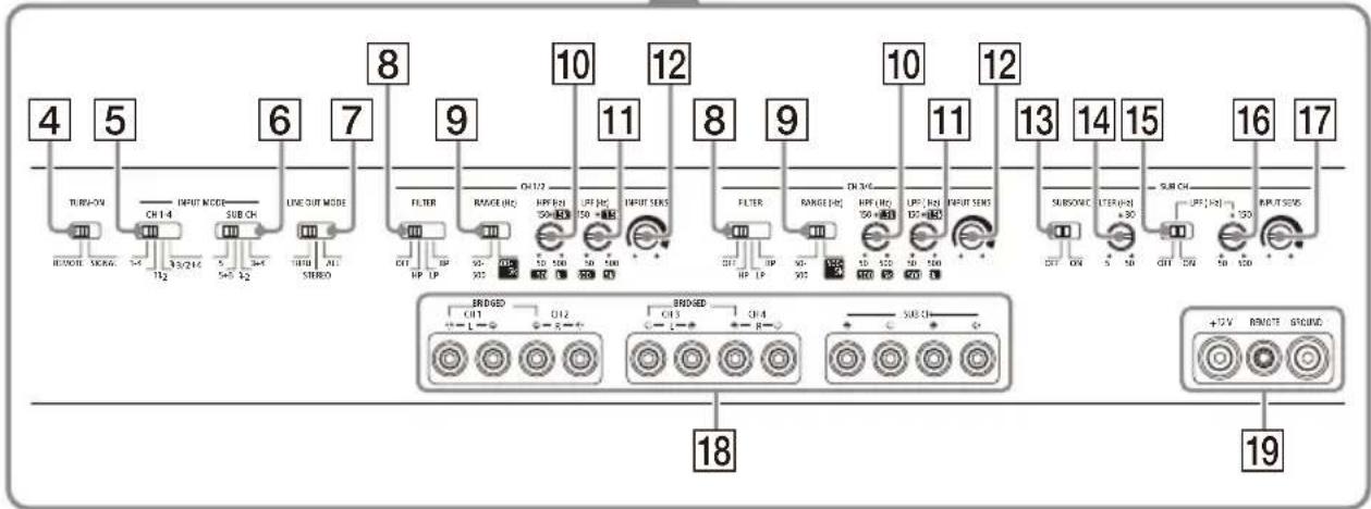
Guide to Parts and Controls
Power Amplifier
Control Panel (Top Panel)
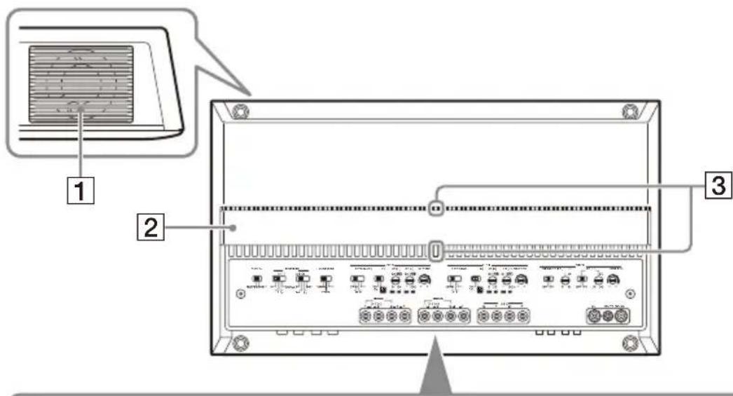

Ventilation outlet
Dissipates heat.
Depending on the temperature of the amplifier, the fan operates in one of the three statuses: stopped, low-speed, high-speed.
Heat sink cover
The direction of the heat sink cover can be changed according to your preference (page 9).
3 Status indicator light
Lights up in white during operation. If the protection circuit activates, the status indicator light changes from white to red. For details, see "Troubleshooting" (page 18).
4 TURN-ON switch
Selects the turn-on mode of the amplifier.
- "REMOTE": Select this for remote turn-on mode. The amplifier turns on when a turn-on signal is received from the REMOTE terminal. See "REMOTE terminal" (page 11) for details.
- "SIGNAL": Select this for high-level sensing turn-on mode. The amplifier turns on when a turn-on signal is received from the INPUT connector. This feature is only available for high-level (speaker level) input connection. See "REMOTE terminal" (page 11) for details.
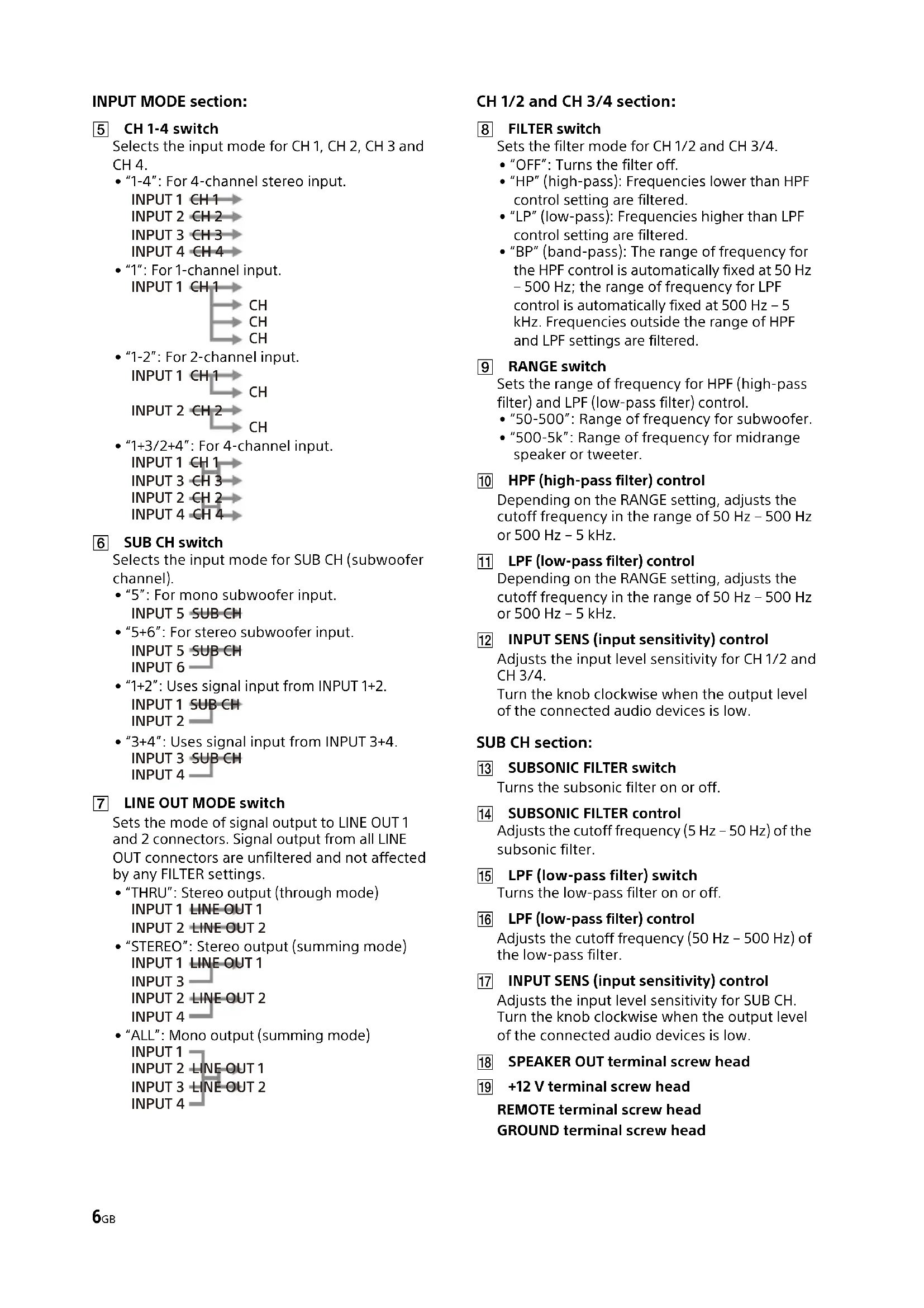
INPUT MODE section:
CH1-4 switch
Selects the input mode for CH 1, CH 2, CH 3 and CH 4.
- "1-4": For 4-channel stereo input.
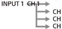
INPUT1CH1
INPUT 2 CH 2
INPUT3CH3
INPUT4CH4
- "1": For 1-channel input.
- "1-2": For 2-channel input.

- "1+3/2+4": For 4-channel input.
INPUT1CH1
INPUT3.CU3
INPUT2CH3
INPUT4.
INPUT4CH4
6 SUB CH switch
Selects the input mode for SUB CH (subwoofer channel).
- "5": For mono subwoofer input.
INPUT 5 SUB CH
- "5+6": For stereo subwoofer input.
INPUT5SUBCH
INPUT6
- "1+2": Uses signal input from INPUT 1+2.
INPUT1 SUBCH
INPUT2
- "3+4": Uses signal input from INPUT 3+4.
INPUT 3 SUB CH
INPUT4
7 LINE OUT MODE switch
Sets the mode of signal output to LINE OUT 1 and 2 connectors. Signal output from all LINE OUT connectors are unfiltered and not affected by any FILTER settings.
- "THRU": Stereo output (through mode)
INPUT1 LINE-OUT1
INPUT2LINEOUT2
- "STEREO": Stereo output (summing mode)
INPUT1 LINEOUT1
INPUT3
INPUT 2 LINE OUT 2
INPUT4
- "ALL": Mono output (summing mode)
INPUT1
INPUT 2 LINE OUT 1
INPUT 3 LINE OUT 2
INPUT4
CH 1/2 and CH 3/4 section:
8 FILTER switch
Sets the filter mode for CH 1/2 and CH 3/4.
- "OFF": Turns the filter off.
- "HP" (high-pass): Frequencies lower than HPF control setting are filtered.
- "LP" (low-pass): Frequencies higher than LPF control setting are filtered.
- "BP" (band-pass): The range of frequency for the HPF control is automatically fixed at 50Hz - 500Hz ; the range of frequency for LPF control is automatically fixed at 500Hz - 5 kHz. Frequencies outside the range of HPF and LPF settings are filtered.
9 RANGE switch
Sets the range of frequency for HPF (high-pass filter) and LPF (low-pass filter) control.
- "50-500": Range of frequency for subwoofer.
- "500-5k": Range of frequency for midrange speaker or tweeter.
HPF (high-pass filter) control
Depending on the RANGE setting, adjusts the cutoff frequency in the range of 50Hz - 500Hz or 500Hz - 5kHz .
LPF (low-pass filter) control
Depending on the RANGE setting, adjusts the cutoff frequency in the range of 50Hz - 500Hz or 500Hz - 5kHz .
12 INPUT SENS (input sensitivity) control
Adjusts the input level sensitivity for CH 1/2 and CH 3/4.
Turn the knob clockwise when the output level of the connected audio devices is low.
SUB CH section:
13 SUBSONIC FILTER switch
Turns the subsonic filter on or off.
14 SUBSONIC FILTER control
Adjusts the cutoff frequency (5 Hz - 50 Hz) of the subsonic filter.
LPF (low-pass filter) switch
Turns the low-pass filter on or off.
LPF (low-pass filter) control
Adjusts the cutoff frequency (50Hz - 500Hz) of the low-pass filter.
17 INPUT SENS (input sensitivity) control
Adjusts the input level sensitivity for SUB CH. Turn the knob clockwise when the output level of the connected audio devices is low.
18 SPEAKER OUT terminal screw head
19 +12 V terminal screw head
REMOTE terminal screw head GROUND terminal screw head
Connector Panel (Front Panel)
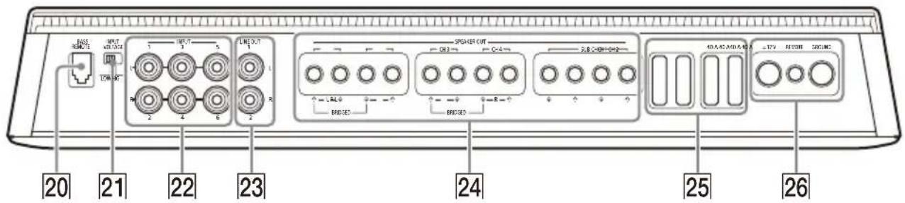
20 BASS REMOTE connector
Connector for the bass remote.
21 INPUT VOLTAGE switch
Selects the type of input connection.
- "LOW": Select this for low-level (line level) input connection using RCA extension cables (not supplied).
"HIGH": Select this for high-level (speaker level) input connection using a speaker-wire-to-RCA adaptor (not supplied).
22 INPUT connector
For details about the connection, see "Input Connection" (page 12).
23 LINE OUT connector
For details about the connection, see "Output Connection" (page 15).
24 SPEAKER OUT terminal
For details about the connection, see "Speaker Connection" (page 14).
25 Fuse (40 A)
26 +12 V terminal
REMOTE terminal
GROUND terminal
Bass Remote
Bass remote adjusts the bass level output of the SUB CH (subwoofer channel). To use, connect the bass remote's cable to the BASS REMOTE connector 20 on the connector panel (front panel).
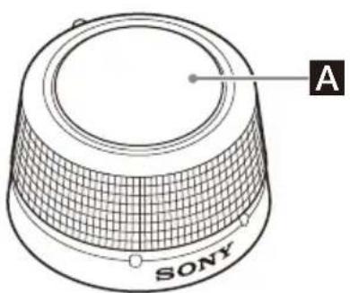
A Volume control knob
Turn the knob clockwise to increase the volume (gain).
Turn the knob counterclockwise to decrease the volume (gain).
CAUTION
Excessive gain input may cause distortion of the sound produced by the connected subwoofer. Do not increase the gain level excessively on the bass remote. The sound produced by the connected subwoofer may also become distorted if the volume of your car audio unit is set too high.
Installation and Connection
Parts for Installation and Connection
① Mounting screw (5× 20mm(1 / 32× 13 / 16in)) (4)
② Mounting bracket (1)


③ Securing screw (2× 5mm /32× 7 / 32in)) (2)
④ Mounting screw (3× 12mm(1 / 8× 1 / 2in)) (2)


Double-sided tape (1) 6
Hex key (2.5 mm ( 3/32 in)1


This parts list does not include all the package contents.
Installation
Installing the Amplifier
- Mount the amplifier either inside the trunk (boot) or under a seat.
- For your safety, choose a mounting location that will not interfere with any driving operations.
- Do not install the amplifier near the heater, in areas that get exposed to direct sunlight or subject to high temperature.
- Do not install the amplifier under a floor carpet where the heat dissipation from the amplifier will be considerably impaired.
- Avoid installing the amplifier in areas subject to rain, moisture, dust and dirt.
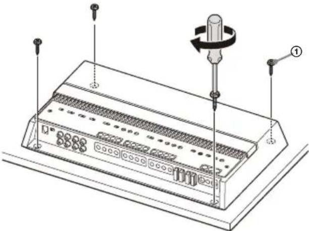
Mounting the amplifier
1 Place the amplifier on your selected mounting location, then mark the position of the 4 screw holes on a mounting board (not supplied).
2 Drill a 3mm (1/8 in) pilot hole at each mark and mount the amplifier onto the board with the mounting screws ①.
The mounting screws 1 are 20mm (13/16 in) long, so make sure that the mounting board is thicker than 20mm (13/16 in).
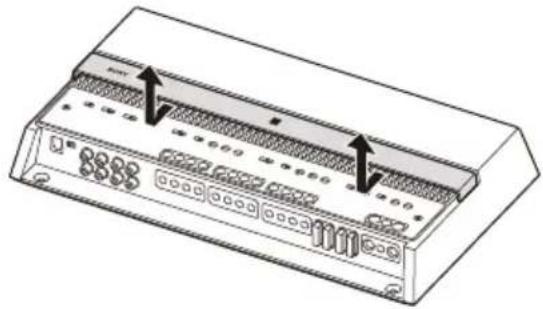
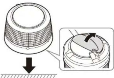
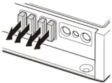
Changing the heat sink cover direction
The direction of the heat sink cover can be changed according to your preference.
1 Slide the cover forward, then lift to remove it.
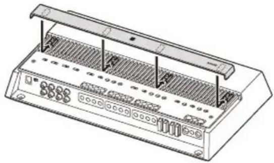
2 Rotate the cover to your desired direction.
3 Align the cover to the catches on the amplifier, then slide the cover back until it clicks into place.
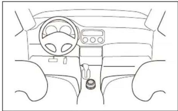
Installing the Bass Remote
- Do not install the bass remote near a heater, in areas that get exposed to direct sunlight or in areas subject to high temperature.
-
Avoid installing the bass remote in areas subject to dust, dirt or moisture.
Install the bass remote in a location where: -
There is a flat surface.
- Does not interfere with the driver's movement.
- Does not hinder the operations of the steering wheel, shift lever or the brake pedal.
Mounting example
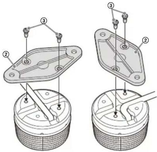
Installing using the mounting bracket
1 Secure the mounting bracket ② to the bass remote using the securing screws ③ You can secure the mounting bracket ② horizontally or vertically to suit your needs.
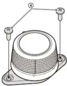
2 Mount the bass remote to your selected mounting location with the mounting screws 4.
Installing using the double-sided tape
1 Apply the double-sided tape ⑤ to the base of the bass remote.
Match the curve of the double-sided tape 5 to that of the bass remote as shown below.
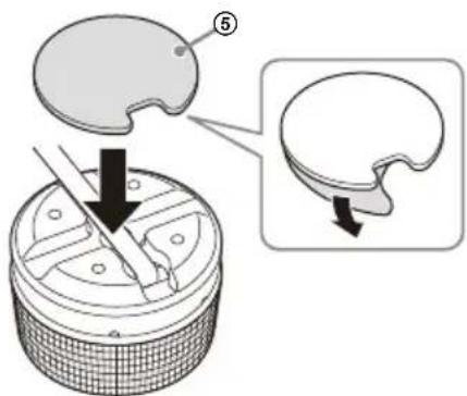
2 Mount the bass remote to a flat surface.
Clean the surface of your selected mounting location with a dry cloth before applying the double-sided tape ⑤.
Connection
- Before making any connections, disconnect the ground (earth) terminal of the car battery to avoid short circuits. Connect this amplifier to the +12V power supply lead only after all other leads have been connected.
- This amplifier is designed for negative ground (earth) 12 V DC operation only.
- Do not operate the amplifier on a weak battery as the amplifier requires a good power supply for optimum performance.
- If your car is equipped with a computer system for purposes such as navigation, disconnecting the ground (earth) terminal of the car battery may damage the computer memory. Leave the ground (earth) lead connected and connect this amplifier to the +12V power supply lead only after all other leads have been connected to prevent short circuits.
- When connecting and installing the input and output cables, keep them away from the +12V power supply lead. Running them close together may generate interference noise.
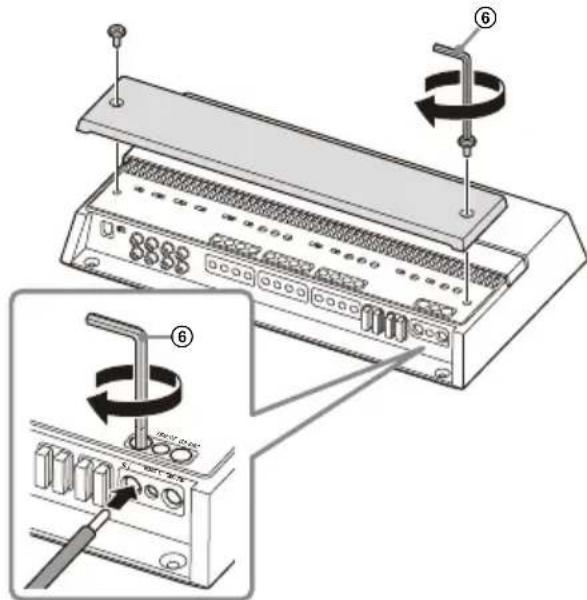
Notes on making connections
- To connect to the terminals on the connector panel and to adjust various settings, remove the top cover to access the control panel (top panel).
- When you tighten the screw, be careful not to apply too much torque as doing so may damage the terminals or cables.
Power Connections
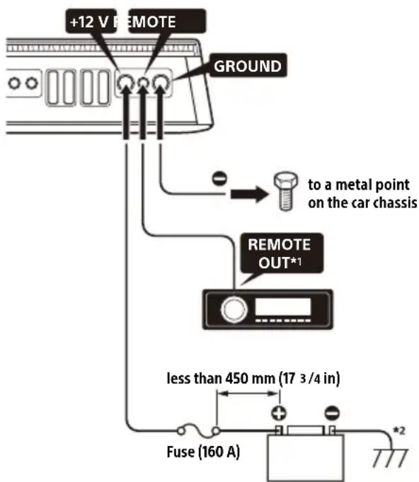
1 If you have the factory original or some other car audio unit without a remote output for the amplifier, connect the remote input (REMOTE) terminal to the ACC power supply. In high level input connection, the amplifier can also be activated without the need of a REMOTE connection. However, this function is not guaranteed for all car audio units.
2 Ground (earth) to the car chassis.
+12 V terminal
- Connect the +12V power supply lead to the +12V terminal only after all the other connections have been completed.
- Use a +12 V power supply lead with a 160 A fuse attached.
- During full-power operation, a current of more than 160A will run through the system. Therefore, make sure the leads to be connected to the +12V terminal are at least 0-Gauge (AWG-1/0) or have a sectional area of more than 55mm^2 ( 2^5/16in^2 ).
- All power leads connected to the positive battery post should be fused within 450mm (17 3/4 in) of the battery post before they pass through any metal.
- Make sure the leads connecting from the car battery to the metal point on the car chassis are at least of a lead gauge equal to that of the +12V power supply lead connected from the battery to the amplifier.
- Make sure the leads connecting from the car battery to the metal point on the car chassis are not more than 0-Gauge (AWG-1/0) or have a sectional area of 55mm^2 (25 / 16in^2) , and at least of a lead gauge equal to that of the +12V power supply lead connected from the battery to the amplifier.
GROUND terminal
- Be sure to connect the ground (earth) lead securely to a metal point on the car chassis. A loose connection may cause the amplifier to malfunction.
- During full-power operation, a current of more than 160 A will run through the system. Therefore, make sure the leads to be connected to the GROUND terminal are at least 0-Gauge (AWG-1/0) or have a sectional area of more than 55mm^2 (2^5/16in^2) .
REMOTE terminal
- To turn on the amplifier using a dedicated remote turn-on lead, set the TURN-ON switch to "REMOTE", then connect the remote output (REMOTE OUT) of your car audio unit to the REMOTE terminal.
- When using a car audio unit without a remote output (REMOTE OUT) for the amplifier, connect the REMOTE terminal to the ACC power supply of your car or use the signal sensing turn-on setting instead.
- Use a remote turn-on lead with a thickness from AWG-8 to AWG-18 or with sectional area from 8.4mm^2 (1/32 in²) to 0.82mm^2 (1/16 in²).
Notes on using high-level sensing turn-on settings
- In high level input connection, the amplifier can also be activated without the need of a REMOTE connection. However, this function is not guaranteed for all car audio units.
- By setting the TURN-ON switch to "SIGNAL", the amplifier operates automatically when a turn-on signal is received from the INPUT connector.
Input Connection
The INPUT connector can be used by both low-level input and high-level input.
Making low-level input connection
Set the INPUT VOLTAGE switch to "LOW" and connect the RCA cable (not supplied) from your car audio to the INPUT connector.
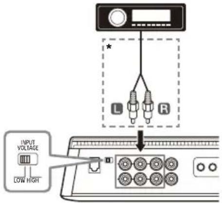
* RCA cable (not supplied)
Making high-level input connection
Set the INPUT VOLTAGE switch to "HIGH" and use a speaker-wire-to-RCA adaptor (not supplied) to connect the speaker wire from your car audio to the INPUT connector.
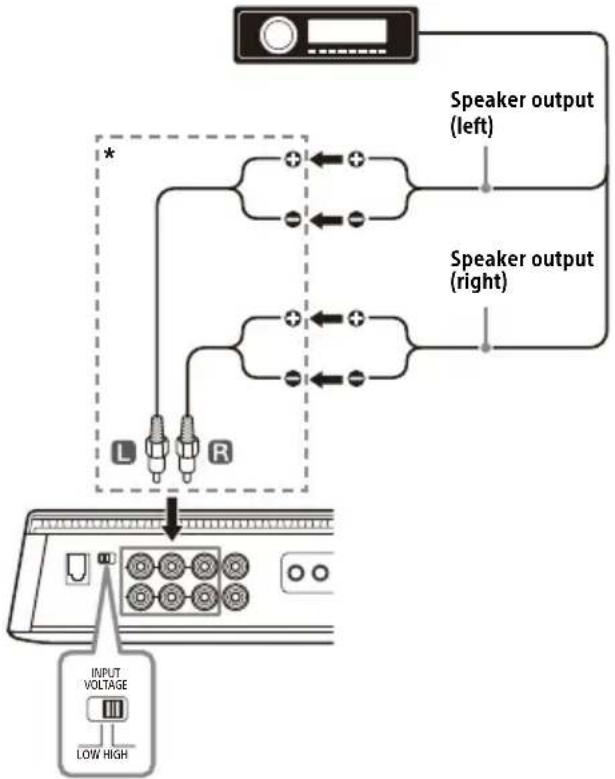
* Speaker wire-to-RCA adaptor (not supplied)
The following shows the connection and settings typically used when connecting a car audio unit and this amplifier. Refer to the operating instructions supplied with your car audio for more details about the input connection for your car audio unit.
A 4-channel input
With "Speaker Connection" (page 14) 1 or 2.
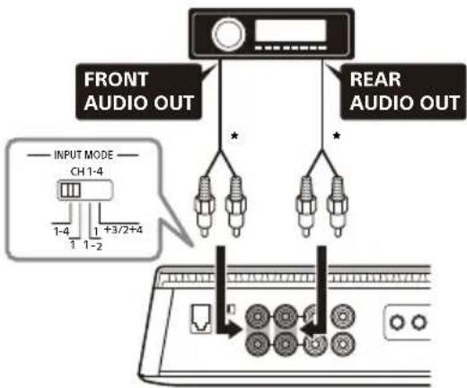
* Use a speaker wire-to-RCA adaptor (not supplied) for high-level input connection.
Note
When making this connection, set the INPUT MODE settings on the control panel (top panel) to the following positions:
- Set CH 1 - 4 to “ 1 - 4 ”
- Set SUB CH to 1 + 2 or 3 + 4 according to your needs.
B 5-channel input
With "Speaker Connection" (page 14) 1 or 2.
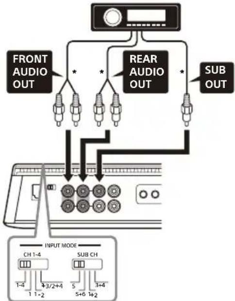
* Use a speaker wire-to-RCA adaptor (not supplied) for high-level input connection.
Note
When making this connection, set the INPUT MODE settings on the control panel (top panel) to the following positions:
- Set CH 1 - 4 to "1 - 4".
- Set SUB CH to "5".
C 6-channel input
With "Speaker Connection" (page 14) 1 or 2.
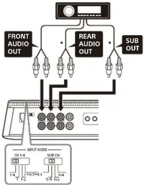
- Use a speaker wire-to-RCA adaptor (not supplied) for high-level input connection.
Note
When making this connection, set the INPUT MODE settings on the control panel (top panel) to the following positions:
- Set CH 1 - 4 to "1 - 4".
- Set SUB CH to "5+6".
D 1-channel input
With "Speaker Connection" (page 14) 1 or 2.
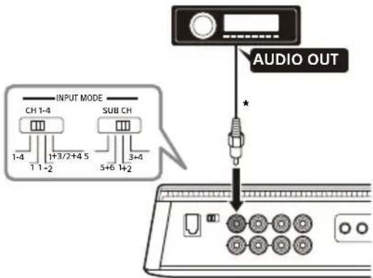
* Use a speaker wire-to-RCA adaptor (not supplied) for highlevel input connection.
Note
When making this connection, set the INPUT MODE settings on the control panel (top panel) to the following positions:
- Set CH 1 - 4 to "1".
- Set SUB CH to "1+2".
E 2-channel input
With "Speaker Connection" (page 14) 1 or 2.
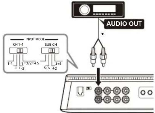
- Use a speaker wire-to-RCA adaptor (not supplied) for high-level input connection.
Note
When making this connection, set the INPUT MODE settings on the control panel (top panel) to the following positions:
-
Set CH 1-4 to "1-2"
-
Set SUB CH to "1+2".
F 4-channel input
With "Speaker Connection" (page 14) 1 or 2.
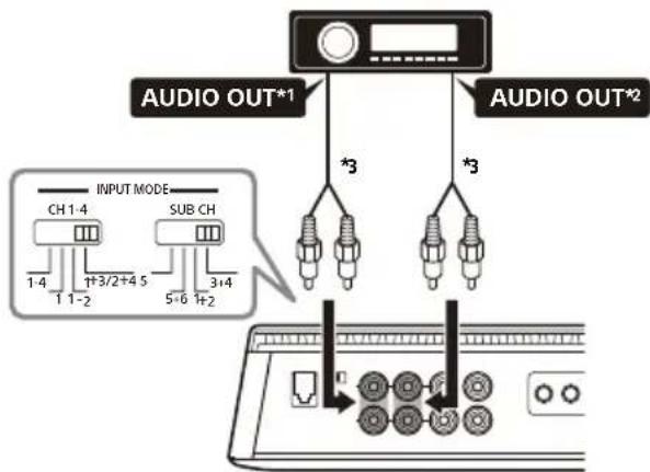
1 Filtered signal. Tweeter output or HPF output from the car audio.
2 Filtered signal. Woofer output or LPF output from the car audio.
*3 Use a speaker wire-to-RCA adaptor (not supplied) for high-level input connection.
Note
When making this connection, set the INPUT MODE settings on the control panel (top panel) to the following positions: - Set CH 1-4 to "1+3/2+4".
- Set SUB CH to "3+4".
G 3-channel input
With "Speaker Connection" (page 14) 3 or 4
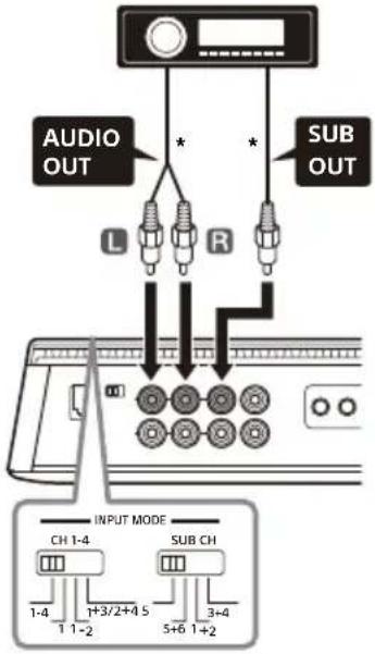
- Use a speaker wire-to-RCA adaptor (not supplied) for high-level input connection.
Note
When making this connection, set the INPUT MODE settings on the control panel (top panel) to the following positions:
-
Set CH 1 - 4 to "1 - 4".
-
Set SUB CH to "5".
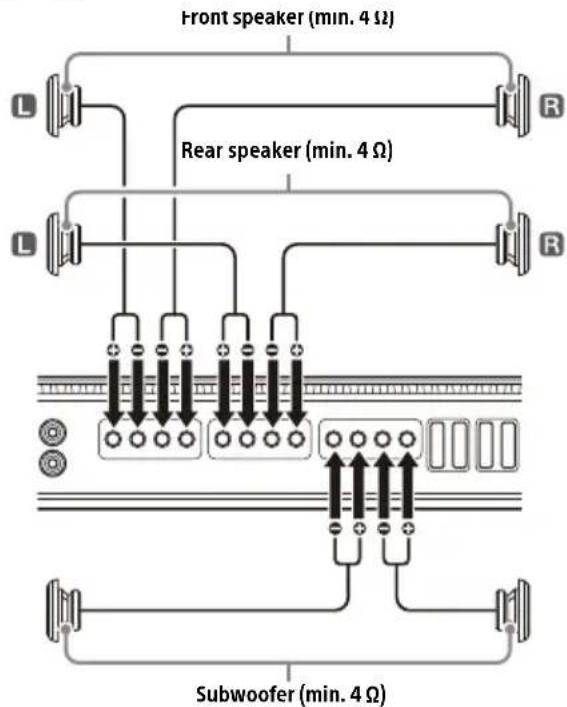
Speaker Connection
- Be sure to use speakers with an adequate power rating. If you use small capacity speakers, they may be damaged.
- Do not connect any active speakers (with built-in amplifiers) to the speaker terminals of the amplifier. Doing so may damage the active speakers.
- Use speakers with an appropriate impedance rating.
-2Ω to 8Ω (stereo)
-4Ω to 8Ω (bridged connection)
- Do not connect the terminal of the speaker system to the car chassis, and do not connect the terminal of the right speaker with that of the left speaker.
Notes
- According to your needs, set the FILTER, RANGE, INPUT SENS, etc. to the appropriate settings for CH 1/2 and CH 3/4
- The following is a depiction of the speaker connections typically used to connect this amplifier. Refer to the operating instructions supplied with your car audio and speakers for more details about the speaker connection for your car audio unit.
1 4 speaker + 2 subwoofer system
With "Input Connection" (page 12) A, B, C, D, E or F.
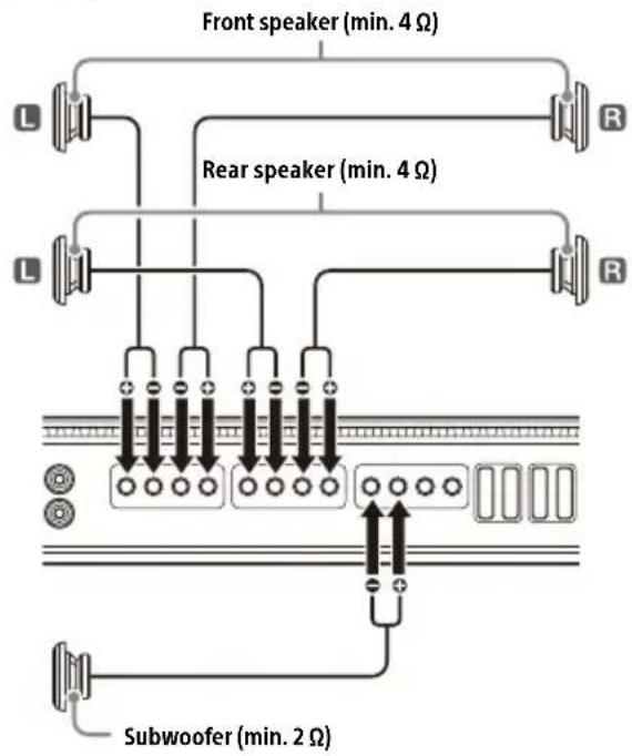
4 speaker + 1 subwoofer system
With "Input Connection" (page 12) A, B, C, D, E or F.
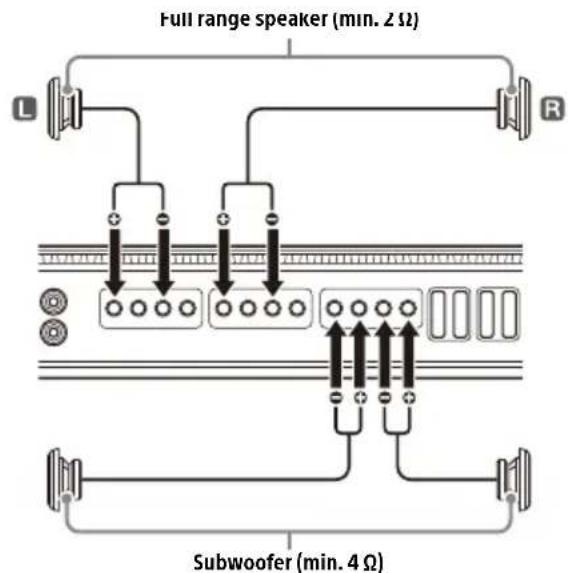
3 2 bridged speaker + 2 subwoofer system
With "Input Connection" (page 12) G.
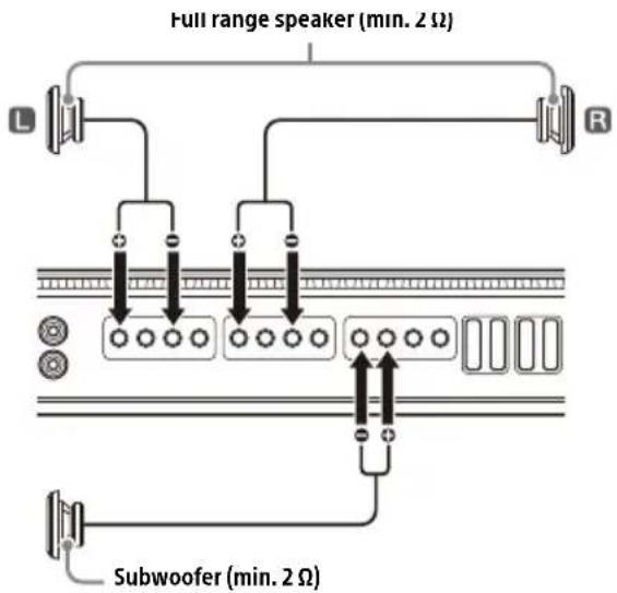
4 2 bridged speaker +1 subwoofer system
With "Input Connection" (page 12) G.
Output Connection
Through the LINE OUT connector, this amplifier can output signals to additional amplifiers. This allows a flexible system connection that utilizes multiple amplifiers.
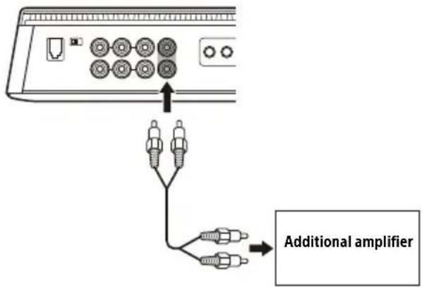
Notes
- Audio signals output from LINE OUT connectors are not affected by any signal processing, such as the HPF and LPF settings.
- According to your needs, set the LINE OUT MODE switch on the control panel (top panel) to "THRU", "STEREO" or "ALL".
Refer to the operating instructions supplied with your additional amplifier for connection details.
Additional Information
Precautions
- This power amplifier employs a protection circuit to protect the transistors and speakers if the amplifier malfunctions. Do not attempt to test the protection circuits by covering the heat sink or connecting improper loads.
- If your car is parked in direct sunlight and there is a considerable rise in temperature inside the car, allow the unit to cool down before use.
- For safety, keep the volume of the unit at a moderate level that allows you to sufficiently hear the sound of traffic outside the vehicle.
- Do not splash liquid onto the amplifier.
* Protection circuit
This amplifier is provided with a protection circuit that operates in the following cases:
- When the unit overheats
- When a DC current is generated
- When the speaker terminals are short-circuited The status indicator light will blink, and this unit will shut down. If this happens, stop the media playback, turn off the connected equipment and determine the cause of the malfunction. If this unit has overheated, wait until it cools down before use.
If you have any questions or problems concerning your unit that are not covered in this Operating Instruction, consult your nearest Sony dealer.
Maintenance
Fuse Replacement
When replacing the fuse, be sure to use one matching the amperage rating stated on the original fuse.
If the fuse blows, check the power connection and replace the fuse.
If the fuse blows again after replacement, there may be an internal malfunction. If this happens, consult your nearest Sony dealer.
Warning
Never use a fuse with an amperage rating exceeding the one supplied with the amplifier as this could damage the amplifier.
Specifications
FOR THE CUSTOMERS IN THE USA. POUR LES CLIENTS AUX ETATS-UNIS.
AUDIO POWER SPECIFICATIONS

CTA2006 Standard
Power Output:
100 Watts RMS × 4 Channels at 4 Ohms,
450 Watts RMS × 1 Channel at 4 Ohms and ≤ 1% THD+N;
165 Watts RMS × 4 Channels at 2 Ohms,
750 Watts RMS × 1 Channel at 2 Ohms
and ≤ 1% THD+N
Signal to Noise Ratio:
77 dBA (reference: 1 Watt into 4 Ohms)
Circuit system:
Class D Technology circuit
Pulse power supply
Inputs:
RCA pin jacks
Input level adjustment range:
0.2 V - 8 V (RCA pin jacks)
3 V - 16 V (high-level input)
Outputs:
Speaker terminals
RCA pin jacks
Speaker impedance:
2Ω-8Ω(stereo)
4 -8 when used as a bridging amplifier
Maximum output:
4 Speakers: 237.5 W × 4 (at 2 Ω) / Total 950 W
1 Woofer/Subwoofer: 950 W (at 2 Ω)
Rated output:
2 Speakers: 330W× 2 (at 4
4 Speakers: 165W× 4 (at 2 ), 100W× 4 (at 4 )
1 Woofer/Subwoofer: 450W× 1 (at 4
1 Woofer/Subwoofer: 750W× 1 (at 2
Frequency response:
CH 1-4: 10Hz - 40kHz (AB)
SUB CH:10 Hz-500 Hz (GB)
THD (total harmonic distortion):
0.05% or less (at 1 kHz, 4 Ω)
Low-pass filter:
50 Hz - 500 Hz, 12 dB/oct
500 Hz - 5 kHz, 12 dB/oct
High-pass filter:
50 Hz - 500 Hz, 12 dB/oct
500 Hz - 5 kHz, 12 dB/oct
Subsonic filter:
5 Hz - 50 Hz, 24 dB/oct
Power requirements:
12 V DC car battery (negative ground (earth))
Power supply voltage:
10.5 V - 16 V
Current drain:
At rated output:
30 A (4 Ω, 100 W × 4)
80 A (2 Ω, 750 W × 1)
Remote input: 4mA
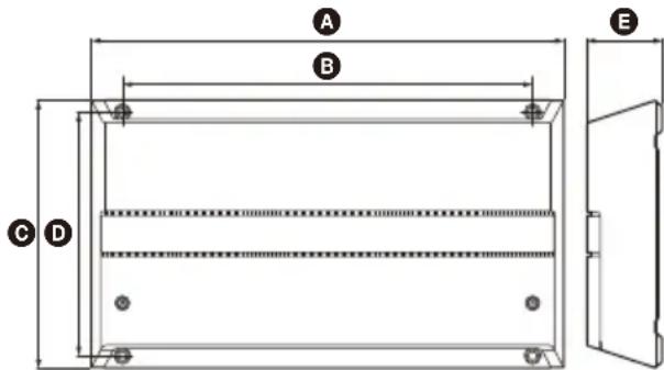
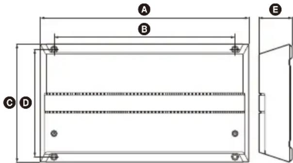
Dimensions:
Approx. 380mm× 60mm× 215mm (15 in ×
2 3/8 in × 8 1/2 in) (w/h/d)
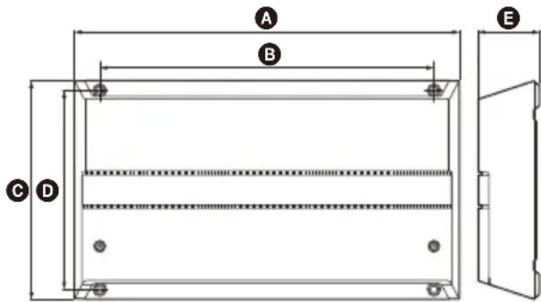
A 380 mm (15 in)
330 mm (13 in)
215 mm (8 1/2 in)
196 mm (7 3/4 in)
60 mm (2 3/8 in)
Mass:
Approx. 4.3kg (9 lb 8 oz) not incl. accessories
Package contents:
Main unit (1)
Bass remote (1)
Parts for installation and connection (1 set)
Design and specifications are subject to change without notice.
Troubleshooting
The following checklist will assist in the correction of most of the problems you may encounter with your unit. Please refer to the connection and operating procedures before going through the checklist below.
The status indicator light does not light up.
The fuse is blown.
- Replace the fuse with a new one.
The ground (earth) lead is not securely connected.
- Fasten the ground (earth) lead securely to a metal point on the car chassis.
The voltage going into the remote input (REMOTE) terminal is too low.
- Turn on the car audio unit if it is not turned on.
- Use a relay if the system employs too many amplifiers.
Check the battery voltage (10.5 V - 16 V).
The status indicator light changes from white to red.
Turn off the amplifier. The speaker outputs have shorted.
- Rectify the cause of the short.
Turn off the amplifier. Make sure the speaker lead and ground (earth) lead are securely connected.
The amplifier becomes abnormally hot.
The amplifier heats up abnormally.
- Use speakers with suitable impedance: 2 - 8 (stereo) or 4 - 8 (when used as a bridging amplifier).
Make sure to place the amplifier in a well ventilated location.
The sound is interrupted.
The thermal protector has activated.
- Reduce the volume.
Alternator noise is heard.
The power connecting leads are installed too close to the RCA pin cables.
- Keep the leads away from the cables.
The ground (earth) lead is not securely connected.
- Fasten the ground (earth) lead securely to a metal point of the car.
Negative speaker wires are touching the car chassis.
- Keep the wires away from the car chassis.
The sound is muffled.
The FILTER switch is set to "LP".
- When connecting the full range speaker, set to "OFF" or "HP".
The sound is too quiet.
The INPUT SENS control setting is not appropriate. Turn the INPUT SENS control in the clockwise direction.
If these solutions do not help improve the situation, consult your nearest Sony dealer.
Support Site
If you have any questions for the latest support information on this product, please visit the website below:
Customers in the USA/Canada/Latin America: https://www.sony.com/am/support
Customers in European countries:
https://www.sony.eu/support
Customers in other countries/regions:
https://www.sony- asia.com/support
Installation et raccordements
Installation et raccordements
500 Hz - 5 kHz, 12 dB/oct
Filtre salle-haut :
50 Hz - 500 Hz, 12 dB/oct
500 Hz - 5 kHz, 12 dB/oct
Filtre subsonique :
5Hz-50Hz,24dB/oc
Alimentation requise :
80 A (2 Ω, 750 W × 1)
Appareil principal (1)
https://www.sony.com/am/support
https://www.sony.eu/support
https://www.sony-asia.com/support
80 A (2 Ω, 750 W × 1)
https://www.sony.com/am/support
https://www.roy.eu/support
https://www.sony-asia.com/support
6 Interruptor SUB CH
Conector BASS REMOTE
23 Conector LINE OUT
80 A (2 Ω, 750 W × 1)
Entrada remota: 4 mA
Dimensiones:
Aprox. 380mm× 60mm× 215mm (an./al./pr.)

A 380mm
330mm
215 mm
196 mm
60mm
Peso:
https://www.sony.com/am/support
Clients de paises europeos:
https://www.roy.eu/support
https://www.sony-asia.com/support
Bedieningspaneel (bovenpaneel)

1 Ventilateopening
500 Hz - 5 kHz, 12 dB/oct
Hoogdoorlaatfilter:
50 Hz - 500 Hz, 12 dB/oct
500 Hz - 5 kHz, 12 dB/oct
Subsonisch filter:
5 Hz - 50 Hz, 24 dB/oct
Voedingsvereisten:
12 V DC-autoaccu (negative massa)
Voedingsspanning:
10,5V-16V
Stroomverbruik:
80 A (2 Ω, 750 W × 1)
Afstandsbedieningsingang: 4 mA
Afmetingen:
Ong. 380mm× 60mm× 215mm(b / h / d)
A 380mm
330mm
215 mm
196 mm
60mm
Gewicht:
Ong. 4,3 kg excl. accessoires
https://www.sony.com/am/support
https://www.roy.eu/support
https://www.sony-asia.com/support
THD (total harmonisk distorsion):
0,05 % aller mindre (vid 1 kHz, 4 Ω)
Lagpassfilter:
50 Hz - 500 Hz, 12 dB/okt
500 Hz - 5 kHz, 12 dB/okt
Högpassfilter:
50 Hz - 500 Hz, 12 dB/okt
500 Hz - 5 kHz, 12 dB/okt
Subsonicfilter:
5 Hz - 50 Hz, 24 dB/okt
Stromforsorjninger:
Bilbatteri pä 12 V DC (negativ jordning)
Spanning:
10,5V-16V
Lackström:
Vid markeffekt:
30 A (4 Ω, 100 W × 4)
80 A (2 Ω, 750 W × 1)
Fjarringang: 4 mA
Matt:
Ca. 380mm× 60mm× 215mm (b/h/d)
A 380mm
330 mm
215 mm
196 mm
60mm
Vikt:
Ca 4,3 kg exclusive tillbehör
https://www.sony.com/am/support
Kunderi Europa:
https://www.roy.eu/support
Kunderi andra lander/regioner:
https://www.sony-asia.com/support


- 5-Channel Power Amplifier
- Owner's Record
- Made in Thailand
- Notice for customers: the following information is only applicable to equipment sold in countries applying EU directives
- Disposal of waste batteries and electrical and electronic equipment (applicable in the European Union and other countries with separate collection systems)
- Features
- Table of Contents
- Guide to Parts and Controls
- Installation and Connection
- Additional Information
- Power Amplifier
- Control Panel (Top Panel)
- Ventilation outlet
- Heat sink cover
- Status indicator light
- TURN-ON switch
- INPUT MODE section:
- CH1-4 switch
- SUB CH switch
- LINE OUT MODE switch
- CH 1/2 and CH 3/4 section:
- FILTER switch
- RANGE switch
- HPF (high-pass filter) control
- LPF (low-pass filter) control
- INPUT SENS (input sensitivity) control
- SUB CH section:
- SUBSONIC FILTER switch
- SUBSONIC FILTER control
- LPF (low-pass filter) switch
- INPUT SENS (input sensitivity) control
- SPEAKER OUT terminal screw head
- +12 V terminal screw head
- Connector Panel (Front Panel)
- BASS REMOTE connector
- INPUT VOLTAGE switch
- INPUT connector
- LINE OUT connector
- SPEAKER OUT terminal
- Fuse (40 A)
- +12 V terminal
- REMOTE terminal
- GROUND terminal
- Bass Remote
- A Volume control knob
- CAUTION
- Parts for Installation and Connection
- Installation
- Installing the Amplifier
- Mounting the amplifier
- Changing the heat sink cover direction
- Installing the Bass Remote
- Mounting example
- Installing using the mounting bracket
- Installing using the double-sided tape
- Connection
- Notes on making connections
- Power Connections
- +12 V terminal
- Notes on using high-level sensing turn-on settings
- Input Connection
- Making low-level input connection
- Making high-level input connection
- A 4-channel input
- Note
- B 5-channel input
- C 6-channel input
- D 1-channel input
- E 2-channel input
- F 4-channel input
- G 3-channel input
- Speaker Connection
- Notes
- 4 speaker + 2 subwoofer system
- speaker + 1 subwoofer system
- 2 bridged speaker + 2 subwoofer system
- 2 bridged speaker +1 subwoofer system
- Output Connection
- Precautions
- * Protection circuit
- Maintenance
- Fuse Replacement
- Warning
- Specifications
- FOR THE CUSTOMERS IN THE USA. POUR LES CLIENTS AUX ETATS-UNIS.
- AUDIO POWER SPECIFICATIONS
- Troubleshooting
- The status indicator light does not light up.
- The status indicator light changes from white to red.
- The amplifier becomes abnormally hot.
- The sound is interrupted.
- Alternator noise is heard.
- The sound is muffled.
- The sound is too quiet.
- Support Site
- Customers in the USA/Canada/Latin America: https://www.sony.com/am/support
- https://www.sony.eu/support
- Installation et raccordements
- Interruptor SUB CH
- Conector BASS REMOTE
- Conector LINE OUT
- Bedieningspaneel (bovenpaneel)
- Ventilateopening
Brand : SONY
Model : XM5ES
Category : Hi-Fi System