
Solo R765.8 HD - Tractor AL-KO - Free user manual and instructions
Find the device manual for free Solo R765.8 HD AL-KO in PDF.

| Product type | Ride-on lawn tractor |
| Brand | AL-KO |
| Model | Solo R765.8 HD |
| Engine | Briggs & Stratton Series 950 E, 223 cm³, 3.97 kW (5.4 hp) |
| Start | Electric and manual (recoil starter) |
| Engine speed | 3000 rpm |
| Fuel tank capacity | 1.1 L (unleaded petrol, min. 91 RON) |
| Cutting width | 61.6 cm |
| Cutting height | 25 to 75 mm, adjustable to 4 positions |
| Maximum speed (forward/reverse) | 5.9 km/h / 3.0 km/h |
| Transmission | Foot-operated hydrostatic (Hydro Gear T1) |
| Weight | 125 kg |
| Grass catcher volume | 130 L with fill indicator |
| Grass catcher emptying | Mechanical by telescopic lever from the seat |
| Blade clutch | Belt-driven mechanical |
| Number of blades | 1 |
| Front/rear tires | 11x4.0-5 / 13x5.0-6, pressure 1.0-1.4 bar |
| Turning radius | 125 cm |
| Safety devices | Brake switch, cutting deck switch, seat switch, grass catcher switch, covers |
| Sound level (guaranteed LwA) | 98 dB(A) |
| Vibrations (hand-arm) | 3.45 m/s² (left) / 2.66 m/s² (right) |
Frequently Asked Questions - Solo R765.8 HD AL-KO
User questions about Solo R765.8 HD AL-KO
0 question about this device. Answer the ones you know or ask your own.
Ask a new question about this device
Download the instructions for your Tractor in PDF format for free! Find your manual Solo R765.8 HD - AL-KO and take your electronic device back in hand. On this page are published all the documents necessary for the use of your device. Solo R765.8 HD by AL-KO.
USER MANUAL Solo R765.8 HD AL-KO
natural_image
Line drawing of a small electric vehicle with visible wheels, suspension panels, and control panel (no text or symbols)


Inhaltsverzeichnis
Deutsch 10
English....31
Nederlands 51
Français....72
Italiano 94
Slovenščina 115
Hrvatski....135
Српски....155
Polski 177
Česky 199
Slovenská 218
Dansk 239
Svensk 258
Norsk 277
Latviešu 296
Русский 316
© 2022
AL-KO KOBER GROUP Kötz, Germany
This documentation or excerpts therefrom may not be reproduced or disclosed to third parties without the express permission of the AL-KO KOBER GROUP.
01
* R7-62.5, R7-63.8 A
** R7-65.8 HD
02

03
* R7-62.5, R7-63.8 A
** R7-65.8 HD
04
natural_image
Mechanical assembly diagram showing engine components and fan assembly (no text or labels)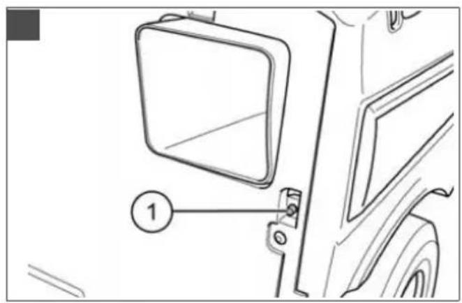
1 About these instructions for use .... 32
1.1 Symbols on the title page.... 32
1.2 Legends and signal words ...... 32
2 Product description 32
2.1 Designated use 32
2.2 Possible foreseeable misuse .... 32
2.3 Safety and protective devices ..... 33
2.4 Symbols on the appliance 33
2.5 Product overview (01, 02) ...... 33
3 Safety instructions .... 34
4 Unpacking and assembling the ride-on mower 34
5 Controls 34
5.1 Controlling the engine speed (03) ..... 34
5.2 Ignition lock (04).... 34
5.3 Brake/clutch pedal (05), brake pedal (06).... 34
5.4 Transmission operation [driving speed] 35
5.4.1 Operating the manual transmission (03, 05, 07).... 35
5.4.2 Operating the foot hydrostat transmission (03, 08) ...... 35
5.5 Operating the mower mechanism (09, 10)....35
6 Start-up 36
6.1 Checking the mower mechanism ..... 36
6.2 Filling with oil (11, 12) 36
6.3 Filling with fuel (11, 13) 36
6.4 Check tyre pressure (14).... 36
6.5 Hooking in and removing the grass catcher (15) 37
6.6 Checking the safety devices 37
6.6.1 Checking the brake contact switch (03, 04) .... 37
6.6.2 Checking the mower mechanism contact switch 37
6.6.3 Checking the seat contact switch (16) 37
6.6.4 Checking the grass catcher contact switch (17, 18).... 37
6.6.5 Visual inspection of the mower mechanism and belt covers ..... 38
7 Operating the ride-on mower.... 38
7.1 Fundamental preparatory measures .. 38
7.2 Use of accessories 38
7.3 Pushing the ride-on mower (03, 19) ... 38
7.4 Starting and shutting off the engine.... 38
7.5 Driving with the ride-on mower 39
7.5.1 Starting off and stopping with manual transmission 39
7.5.2 Starting off and stopping with foot hydrostat transmission 39
7.5.3 Preparing to drive at temperatures below 10 °C.... 39
7.5.4 Driving and mowing on slopes ..... 40
7.6 Mowing with the ride-on mower...... 40
7.6.1 Switching on the mower mechanism 40
7.6.2 Mowing in reverse...... 40
7.6.3 Switching off the mower mechanism 41
7.6.4 Emptying the grass catcher (22, 23).... 41
7.6.5 Mowing interval 41
7.6.6 Mowing high grass 41
7.6.7 Cutting blade maintenance ..... 41
8 Cleaning the ride-on mower 42
8.1 Cleaning the grass catcher.... 42
8.2 Cleaning the deck, engine and transmission.... 42
8.3 Cleaning the discharge channel ..... 42
8.4 Cleaning the mowing system...... 42
9 Maintenance.... 43
9.1 Maintenance schedule.... 43
9.2 Lubricating plan 44
9.3 Cleaning the air filter (11, 25) ..... 44
9.4 Checking the spark plug (26, 27, 28).. 44
9.5 Adjusting the Bowden cable for the mower mechanism (29).... 45
9.6 Adjusting the mower mechanism (30) 45
9.7 Starter battery 45
10 Transport 46
11 Storage 46
12 Help in case of malfunction...... 46
13 Technical data 48
14 After-Sales/Service 50
15 Guarantee.... 50
1 ABOUT THESE INSTRUCTIONS FOR USE
The German version is the original operating instructions. All additional language versions are translations of the original operating instructions.
■ Always safeguard these operating instructions so that they can be consulted if you need any information about the appliance.
■ Only pass on the appliance to other persons together with these operating instructions.
■ Comply with the safety and warning information in these operating instructions.
The ride-on mowers are supplied with different levels of equipment. Please note that the illustrations may differ somewhat from the original. Please contact a specialist workshop or the manufacturer if you encounter difficulties in following the descriptions.
■ Comply with the supplied assembly instructions.
1.1 Symbols on the title page
Symbol Meaning

It is essential to read through these operating instructions carefully before start-up. This is essential for safe working and trouble-free handling.

Operating instructions
Symbol Meaning

Never operate the petrol powered device in the vicinity of open flames or heat sources.
1.2 Legends and signal words
⚠️ DANGER! Denotes an imminently dangerous situation which will result in fatal or serious injury if not avoided.
WARNING! Denotes a potentially dangerous situation which can result in fatal or serious injury if not avoided.
CAUTION! Denotes a potentially dangerous situation which can result in minor or moderate injury if not avoided.
IMPORTANT! Denotes a situation which can result in material damage if not avoided.
NOTE Special instructions for ease of understanding and handling.
2 PRODUCT DESCRIPTION
2.1 Designated use
The ride-on mower is intended for mowing in domestic gardens and allotments with a max. slope of 8^ (15 %). Additional applications, such as for mulching, are only permitted if the original accessories are used and in compliance with the maximum load values.
This trailer is intended solely for use in non-commercial applications. Any other use (as well as unauthorised conversions or add-ons) are regarded as contrary to the intended use and will result in exclusion of the warranty as well as loss of conformity (CE mark); the manufacturer will thus decline any responsibility for damage and/or injury suffered by the user or third parties.
2.2 Possible foreseeable misuse
The ride-on mower is not designed for commercial use in public parks, sports grounds, agriculture and forestry.
WARNING! Dangers due to overloading the ride-on mower! Make sure that the permissible inclines/declines are not exceeded. Exceeding these values may exceed the braking capacity of the ride-on mower and lead to dangerous situations!
NOTE Bear in mind that the ride-on mower does not have approval for road use, and thus is not allowed to be driven on public roads!
2.3 Safety and protective devices
WARNING! Danger if protective devices are removed or manipulated! Do not operate with any protective devices removed or manipulated. Defective protective devices must be repaired or renewed immediately!
Above all, the protective devices include:
- Brake contact switch
■ Mower mechanism contact switch
Grass catcher contact switch - Seat contact switch
■ Mower mechanism covers
Belt covers
2.4 Symbols on the appliance

Before starting operation, read the operating instructions.
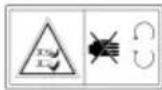
Keep other people, especially children and animals, out of the working area during mowing.

Remove the ignition key before maintenance and repair work!

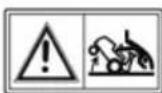
Important – danger! Keep your hands and feet away from the blade system.


Do not drive on gradients of more than 8° (15%)!
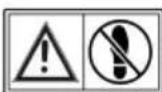
Danger: Do not step here!

Risk of burns on hot surfaces!
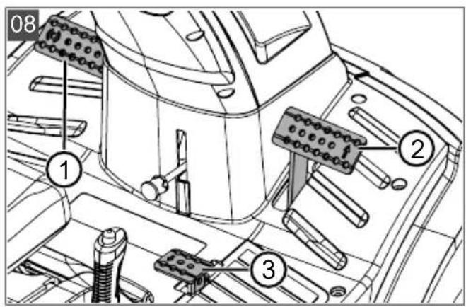
2.5 Product overview (01, 02)
No. Component
| 1 Steering wheel |
| 2 Safety sticker |
| 3 Operator's seat |
| 4 Grass catcher |
| 5 Selector lever* |
| 6 Release lever for reverse gear* |
7 Bonnet
8 Mower mechanism
9 Cleaning fitting
10 Front wheels, steered
11 Mower mechanism lever
12 Brake pedal**
13 Lever for grass catcher
14 Throttle lever with choke
15 Ignition lock
16 Locking lever for brake/clutch pedal
17 Brake/clutch pedal* Forwards pedal**
18 Reverse pedal**
19 Enable button for reverse mowing**
20 Adjusting lever for cutting height
21 Cable starter handle
22 Rear wheels, driven
23 Discharge channel
24 Bypass lever**
25 Fill level sensor***
26 Engine cover
* On R7-62.5 and R7-63.8 A only
** On R7-65.8 HD only
*** Not on R7-62.5
3 SAFETY INSTRUCTIONS
Children, or other people who are not familiar with the instructions for use, are not allowed to use the equipment.
■ Comply with local regulations on the minimum age of people operating the equipment.
- Do not allow children and young people to play on the machine.
■ Only mow during daylight hours or with good artificial lighting.
- Keep other people out of the danger area.
■ The user is responsible for accidents involving other people and their property.
■ Only use genuine spare parts and genuine accessories.
■ Repairs on the machine must be carried out by the manufacturer or by one of its customer service centres.
■ Wear ear defenders.
The ride-on mower does not have approval for road use and may not be driven on public roads.
- Do not mow during thunderstorms. No protection against lightning strikes.
- Do not carry any passengers on the machine.
- Do not mow on slopes with a gradient of more than 8° (15 %).
■ Never drive transversely to the slope.
- Do not use the ride-on lawnmower and/or any accessories attached to it in the event of fatigue, illness or after the consumption of alcohol or medications that impair reactions or drugs.
■ Comply with the permitted operating times in your vicinity.
The ride-on mower can cause serious injuries due to its dead weight. Take particular care when loading and unloading the ride-on mower to transport it on a vehicle or trailer.
This ride-on mower is not allowed to be towed. Use a suitable vehicle for transport on public roads.
- Do not operate the ride-on mower in poorly ventilated working areas (e.g. a garage). The exhaust gases contain poisonous carbon monoxide as well as other harmful substances.
- Do not change or manipulate any fixed settings for engine speed regulation.
4 UNPACKING AND ASSEMBLING THE RIDE-ON MOWER
Comply with the supplied assembly instructions for unpacking and assembling the ride-on mower.
WARNING! Danger if assembly is not carried out completely! Do not operate the ride-on mower before it has been fully assembled! Carry out all the work described in the assembly instructions. If you are uncertain about anything, ask a specialist to confirm that the assembly has been carried out correctly before the machine is started up! Check whether all safety and protective devices are in place and functioning correctly!
5 CONTROLS
The ride-on mower controls are described in the following.
5.1 Controlling the engine speed (03)
NOTE Please note that operating the controller while driving influences the speed!
For controller with integrated choke:
Pushing the controller (03/A) increases or reduces the engine speed; in the uppermost position, it engages the choke.

Use this position for starting the engine.
Mowing: In this position, the engine runs at maximum speed.

Idling: In this position, the engine runs at the lowest speed.
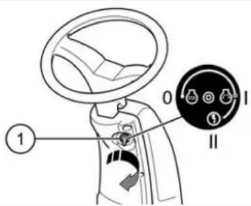
5.2 Ignition lock (04)
| Position | Function |
| 0 | Engine off.The ignition key can be removed. |
| I | Operating position when the engine is running. |
| II | Start position for starting the engine.Release the key as soon as the engine is running. It then springs back to operating position I. |
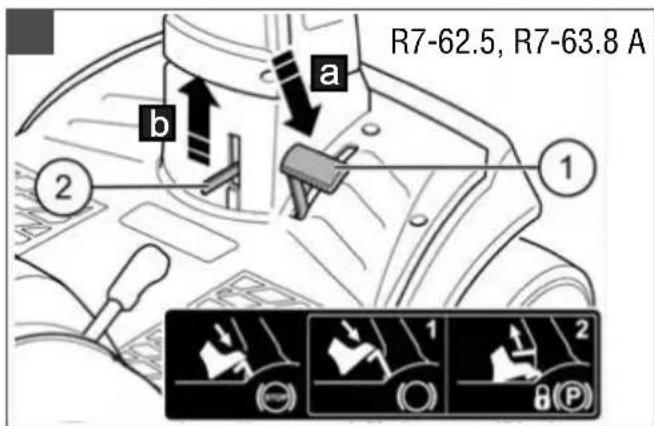
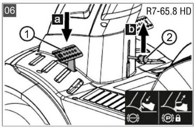
5.3 Brake/clutch pedal (05), brake pedal (06)
Brake
■ With manual transmission: If you press the brake/clutch pedal (05/1) all the way down
(05/a), the drive is decoupled and the brake on the transmission is applied.
■ With foot hydrostat transmission: If you press the brake pedal (06/1) all the way down (06/a), the brake on the transmission is applied.
The ride-on mower brakes.
Parking brake
■ With manual transmission: Pulling the locking lever (05/2) upwards (05/b) while the brake/clutch pedal (05/1) is pressed down locks the brake.
■ With foot hydrostat transmission: Pulling the locking lever (06/2) upwards (06/b) while the brake pedal (06/1) is pressed down locks the brake.
Pressing the pedal again releases the brake.
NOTE The brake/clutch pedal must be pressed down all the way to start the engine.
5.4 Transmission operation [driving speed]
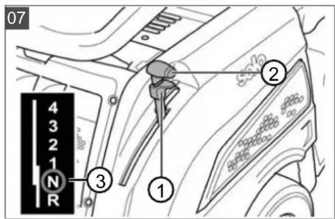
5.4.1 Operating the manual transmission (03, 05, 07)
The manual transmission of the ride-on mower has four forwards gears and one reverse gear. The gears can be selected using a selector lever (03/B, 07/2) on the left of the operator's seat, according to the required driving speed.
Starting the engine
The selector lever must be in the N position (07/3), i.e. neutral, to start the engine.
NOTE The mower mechanism must be switched off to start the engine.
Selecting a gear
- Press the brake/clutch pedal (05/1) down all the way when the engine is running.
- Pull the locking button (07/1) on the selector lever (07/2) all the way up.
- Select the gear appropriate to the required direction of travel and driving speed.
- To move off, slowly release the brake/clutch pedal (05/1).
i NOTE If you want to select a lower gear than the one that is engaged, first brake to reduce the speed of the ride-on mower until the speed matches the corresponding gear.
5.4.2 Operating the foot hydrostat transmission (03, 08)
On ride-on mowers with a foot hydrostat transmission, there are two separate pedals on the right-hand side for forwards and reverse travel.
| Direction of travel Description |
| Forwards Press the front pedal(08/2) to drive forwards. |
| Reverse Press the rear pedal(08/3) to drive backwards.Note: The speed is limited when the mower mechanism is switched on.Mowing in reverse (see chapter 7.6.2 "Mowing in reverse", page 40) |
Moving off
Precondition: The engine is running.
- Release the parking brake (03/E, 08/1).
- Select the direction of travel (03/F).
Increasing the speed
The further you press the pedal, the faster your speed will be in the selected direction.
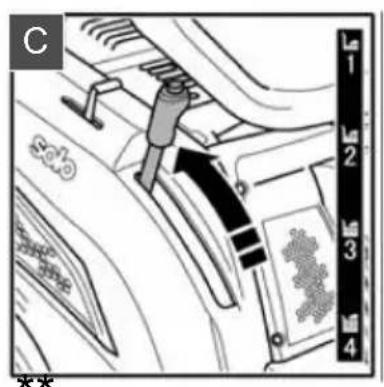
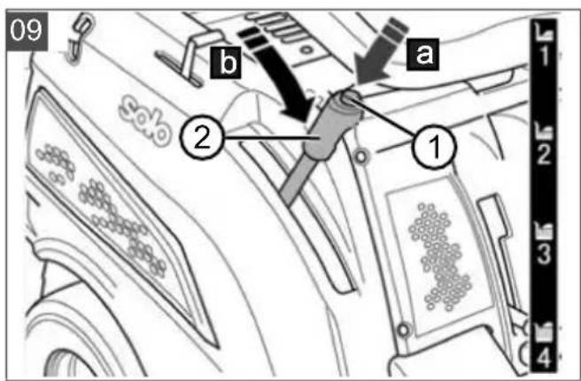
5.5 Operating the mower mechanism (09, 10)
Setting the cutting height
The ride-on mower's mower mechanism can be set to various heights using an adjusting lever (09/2) on the right next to the operator's seat.
-
Press the release button (09/1) on the adjusting lever (09/2) (09/a).
-
Move the adjusting lever in the required direction (09/b):
■ Lever downwards: low cutting height
■ Lever upwards: high cutting height
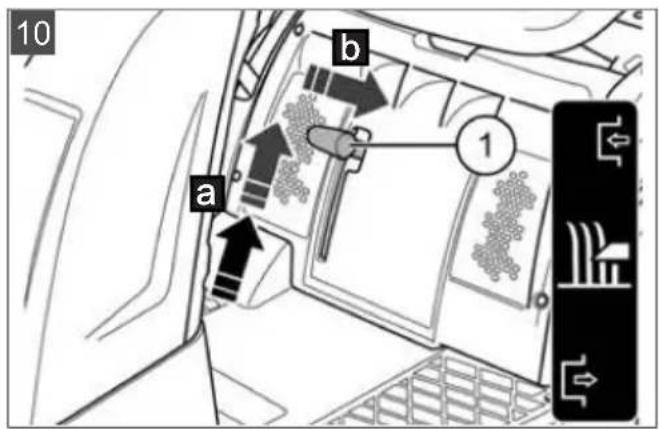
Switching on the mower mechanism
- Set the uppermost cutting height with the adjusting lever (09/2).
Note: The mower mechanism must always be started at the uppermost cutting height.
- Pull the lever (10/1) for switching on the mower mechanism upwards (10/a) and en-
gage it (10/b). The mower mechanism is running.
- Set the required cutting height with the adjusting lever (09/2).
6 START-UP
WARNING! Danger if assembly is not carried out completely! Do not operate the ride-on mower before it has been fully assembled! Carry out all the work described in the assembly instructions. If you are uncertain about anything, ask a specialist to confirm that the assembly has been carried out correctly before the machine is started up! Check whether all safety and protective devices are in place and functioning correctly!
6.1 Checking the mower mechanism
Before use, always look and check whether the cutter, fastening pin and the entire mowing unit are worn or damaged. Worn or damaged blades must be renewed by new ones in order to avoid any imbalance.
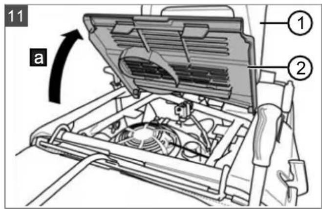
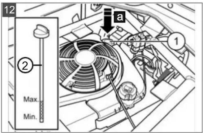
6.2 Filling with oil (11, 12)
NOTE Also comply with the assembly instructions for filling the ride-on mower with engine oil for the first time.
i NOTE For more detailed information, please refer to the separate operating instructions for the engine.
Note that the oil level must be checked at regular intervals and oil must be replenished if necessary.
Use a suitable funnel or a filler pipe when pouring in the oil so that no oil is spilled on the engine, the housing or the ground.
- Fold the seat (11/1) forwards and open the cover (11/2) to the engine compartment (11/a).
- Unscrew the oil filler neck (12/1) cap.
- Pour in oil (12/a) until the oil level can be seen between the MIN and MAX marks on the oil dipstick (12/2). Do not overfill the engine!
- Screw the oil filler neck (12/1) cap on again.
- Close the cover (11/2) to the engine compartment and fold the seat (11/1) back.
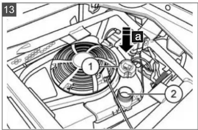
6.3 Filling with fuel (11, 13)
WARNING! Dangers when handling fuel! Fuel is highly inflammable. Only fill the fuel tank outdoors! Do not smoke! Do not refuel when the engine is running or is hot!
NOTE For more detailed information, please refer to the separate operating instructions for the engine.
Use a suitable funnel or a filler pipe when refueling so that no fuel is spilled on the engine, the deck or the ground.
For safety reasons, the fuel tank cap and other tank caps must be renewed if damaged.
Do not start the engine if the fuel has overflowed. The ride-on mower must be removed from the area contaminated by fuel, and the spilled fuel must be absorbed and wiped away from the ground, the engine and the deck using a cloth.
Any attempt to start the mower must be avoided until the fuel vapours have evaporated.
Only keep the fuel in containers intended for this purpose.
Use lead-free petrol, min. RON 91.
Filling the tank
- Switch off the engine and remove the ignition key.
- Wait until the engine has cooled down somewhat (risk of explosion if the fuel catches fire!).
- Fold the seat (11/1) forwards and open the cover (11/2) to the engine compartment (11/a).
-
Open the tank cap (13/1) and pour the fuel into the tank (13/2) (13/a).
Note: Avoid overfilling the fuel tank! -
Close the tank cap (13/1).
-
Close the cover (11/2) to the engine compartment and fold the seat (11/1) back.
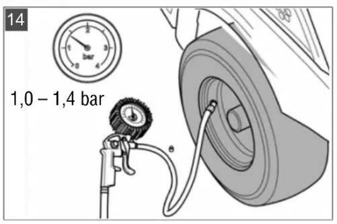
6.4 Check tyre pressure (14)
The correct tyre pressure is an important prerequisite for a correctly levelled mower deck, and hence for a uniformly mown lawn. Check the tyre pressure at regular intervals.
- Park the ride-on mower on firm and level ground and remove the ignition key.
-
Wait for approx. 1 hour after operation to allow the tyre to cool down. The tyre pressure can only be measured correctly when the tyre is cool.
-
Unscrew the valve cap and press a tyre pressure meter onto the open valve.
- Read off the tyre pressure and compare it with the values given on the tyre: 1.0 – 1.4 bar.
- If the tyre pressure is too low: Pump up the tyre using a commercially available foot pump.
NOTE 1 PSI = 0.07 bar.
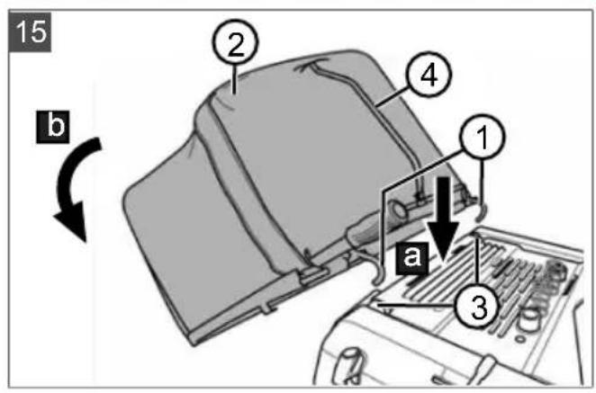
6.5 Hooking in and removing the grass catcher (15)
Hooking in the grass catcher
- Insert the hooks (15/1) of the grass catcher (15/2) into the brackets (15/3) on the ride-on mower (15/a). When doing so, grip the grass catcher by the handle (15/4) and the side facing away from the ride-on mower.
Note: The grass catcher must be hung in symmetrically.
- Tilt the grass catcher downwards (15/b) until it engages on the ride-on mower.
- Check the grass catcher is correctly seated.
Remove the grass catcher
The grass catcher is removed in the reverse sequence.
6.6 Checking the safety devices
The safety devices must be checked each time before starting the ride-on mower.
WARNING! Danger when checking the safety devices! The safety devices may only be checked from the operator's seat and when no other persons or animals are in the vicinity!
Perform all checks on a level surface so that the ride-on mower cannot roll away unintentionally.
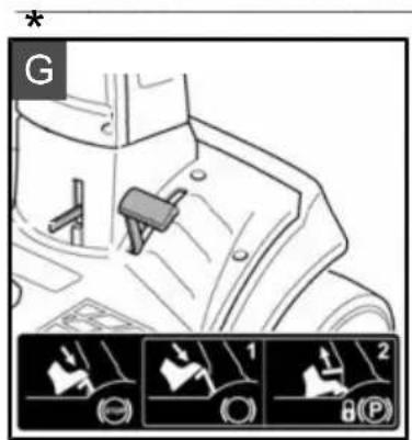
6.6.1 Checking the brake contact switch (03, 04)
The brake contact switch ensures that the engine cannot be started if the brake is not applied.
Precondition: The engine is off.
- Sit on the operator's seat.
- Release the parking brake by applying the brake/clutch pedal (03/G) or the brake pedal (03/E).
- Release the brake/clutch pedal or the brake pedal again.
- Attempt to start the engine, i.e. ignition key in position II (04).
NOTE The engine is not allowed to start!
6.6.2 Checking the mower mechanism contact switch
The mower mechanism contact switch ensures that the engine cannot be started if the mower mechanism is activated.
Precondition: The engine is off.
- Sit on the operator's seat.
- Apply the brake/clutch pedal or the brake pedal (see chapter 5.3 "Brake/clutch pedal (05), brake pedal (06)", page 34).
- Engage the mower mechanism (see chapter 5.5 "Operating the mower mechanism (09, 10)", page 35).
- Attempt to start the engine, i.e. ignition key in position II (04).
NOTE The engine is not allowed to start!
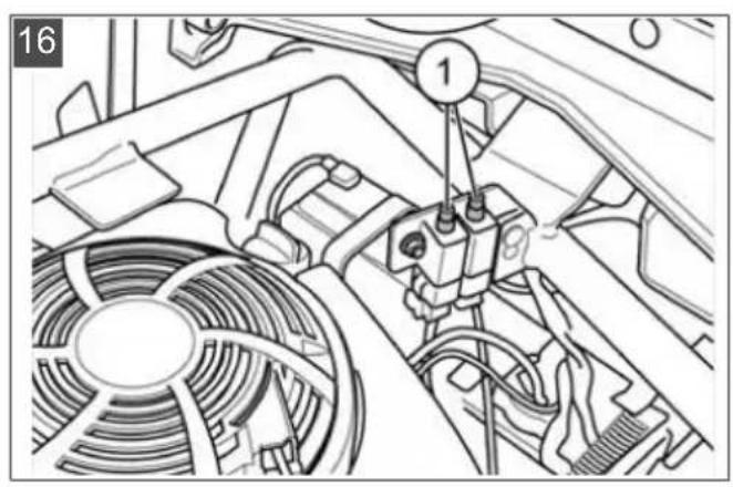
6.6.3 Checking the seat contact switch (16)
The seat contact switch (16/1) ensures that the engine cuts off when nobody is on the operator's seat when the mower mechanism is switched on or when the parking brake is not locked.
- Sit on the operator's seat.
- Apply the brake/clutch pedal or the brake pedal (see chapter 5.3 "Brake/clutch pedal (05), brake pedal (06)", page 34).
- Start the engine and let it run at maximum rpm (see chapter 7.4 "Starting and shutting off the engine", page 38).
- Engage the mower mechanism (see chapter 5.5 "Operating the mower mechanism (09, 10)", page 35).
- Take your weight off the seat by standing up (do not get off!).
NOTE The engine must switch itself off!
6.6.4 Checking the grass catcher contact switch (17, 18)
The grass catcher contact switch (17/1) ensures that the engine cuts off as soon as the grass catcher is not hooked in correctly when the mower mechanism is switched on.
- Sit on the operator's seat.
- Apply the brake/clutch pedal or the brake pedal (see chapter 5.3 "Brake/clutch pedal (05), brake pedal (06)", page 34).
-
Start the engine and let it run at maximum rpm (see chapter 7.4 "Starting and shutting off the engine", page 38).
-
Engage the mower mechanism (see chapter 5.5 "Operating the mower mechanism (09, 10)", page 35).
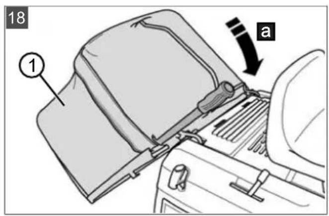
- Raise the empty grass catcher (18/1) slightly (18/a) (see chapter 7.6.4 "Emptying the grass catcher (22, 23)", page 41).
NOTE The engine must switch itself off!
6.6.5 Visual inspection of the mower mechanism and belt covers
Check that the mower mechanism and belt covers are undamaged and thus prevent access to the mower mechanism and the drive belts. If damaged, contact a customer service workshop.
WARNING! Dangers due to inadequate knowledge of the ride-on mower! Read the operating instructions for use carefully before you start! Pay particular attention to all safety instructions! Carry out all assembly and start-up work conscientiously. Ask the manufacturer if you have any doubts!
7.1 Fundamental preparatory measures
■ Always wear tough shoes and long trousers while mowing. Never mow barefoot or when wearing open sandals.
- Check the complete area on which the ride-on mower is to be used. Remove all stones, sticks, wires, bones and other foreign objects which could be scooped up and flung out. Also pay attention to foreign objects during mowing.
- Carry out all the work described in the start-up instructions. This applies in particular to checking the safety devices.
■ Transporting objects on the ride-on mower is prohibited!
7.2 Use of accessories
WARNING! Danger due to incorrect accessories or incorrect use of accessories! Only ever use genuine accessories from the manufacturer! Pay attention to the regulations on use in the supplied operating instructions!
Using unauthorised accessories, or using accessories incorrectly, can expose the operator and other persons to significant risks. The ride-on mower could be overloaded. This can lead to serious accidents.
7.3 Pushing the ride-on mower (03, 19)
CAUTION! Danger when pushing on
slopes! Only push the ride-on mower on horizontal surfaces! On slopes, the ride-on mower could roll downhill uncontrollably.
Pushing with manual transmission
- Release the parking brake (03/G) (see chapter 5.3 "Brake/clutch pedal (05), brake pedal (06)", page 34).
- Move the selector lever (03/B) to the N position.
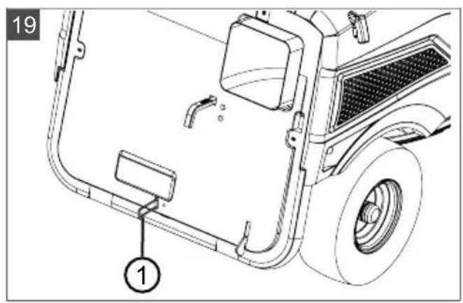
Pushing with foot hydrostat transmission
The bypass lever (19/1) is located at the rear in the lower area of the rear wall. Bypass release:
- Pull out the bypass lever (19/1).
- Release the parking brake (see chapter 5.3 "Brake/clutch pedal (05), brake pedal (06)", page 34). The ride-on mower can now be pushed.
- After pushing, reset the bypass lever (19/1) to enable the hydrostatic transmission again.
7.4 Starting and shutting off the engine
Starting the motor
- Sit on the operator's seat.
- Fully depress the brake/clutch pedal (05/1) or the brake pedal (06/1) and lock it with the locking lever (05/2, 06/2).
- Make sure the mower mechanism is not switched on. To do this, check the position of the lever (03/D).
- With manual transmission: Make sure that the selector lever (03/B) is set to the N position (neutral). To do this, check the position of the selector lever.
- Move the engine speed controller (03/A) to the front end stop. The hare symbol is located there.
- Insert the ignition key into the ignition lock (04/1).
7. Starting the engine (electrically):
■ Turn the ignition key to position "II" and hold it there until the engine is running (04).
Note: To reduce strain on the starter battery, do not attempt to start for any longer than about 5 seconds.
■ Then release the ignition key; it automatically jumps to position "I".
8. Starting the engine (with cable starter):
If the engine cannot be started with the electric starter, check the ride-on mower for mechanical damage. If there is no damage, the engine can also be started with the cable starter.
■ Turn the ignition key to position "I" (04).
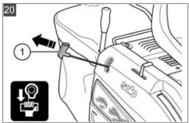
■ Pull the cable starter (20/1) straight out quickly and forcefully 3 to 4 times until the engine is running.
- Move the engine speed controller (03/A) to the operating position.
Switch off the engine
- Shut off the mower mechanism (03/D).
- Move the engine speed controller (03/A) to the neutral position.
- Fully depress the brake/clutch pedal (05/1) or the brake pedal (06/1) and lock it with the locking lever (05/2, 06/2).
-
Turn the ignition key (04/1) to the "0" position.
-
Remove the ignition key.
WARNING! Danger if the engine is hot! When stopping the engine, ensure that hot engine components such as the silencer cannot set fire to objects or materials located nearby!
7.5 Driving with the ride-on mower
WARNING! Danger in case of inappropriate speed! Drive slowly, especially at the beginning, in order to familiarise yourself with the driving and braking behaviour of the ride-on mower! Before each change of direction, adjust the driving speed so as to maintain control of the ride-on mower at all times and to prevent it from tipping over!
7.5.1 Starting off and stopping with manual transmission
- Fully depress the brake/clutch pedal (05/1) or the brake pedal (06/1) and lock it with the locking lever (05/2, 06/2).
- Set the mower mechanism to the maximum cutting height (see chapter 5.5 "Operating the mower mechanism (09, 10)", page 35).
- Start the motor (see chapter 7.4 "Starting and shutting off the engine", page 38).
- Pull the locking button (07/1) on the selector lever (07/2) all the way up.
-
Select the gear appropriate to the required direction of travel and driving speed.
-
To move off, slowly release the brake/clutch pedal (05/1).
- To stop, depress the brake/clutch pedal (05/1).
i NOTE If you want to select a lower gear than the one that is engaged, first brake to reduce the speed of the ride-on mower until the speed matches the corresponding gear.
7.5.2 Starting off and stopping with foot hydrostat transmission
- Depress the brake pedal (06/1) and hold it down.
- Set the mower mechanism to the maximum cutting height (see chapter 5.5 "Operating the mower mechanism (09, 10)", page 35).
- Start the motor (see chapter 7.4 "Starting and shutting off the engine", page 38).
-
Release the brake pedal.
-
Slowly press the foot pedal for the required driving direction:
■ Forwards: Foot pedal (08/2)
■ Reverse: Foot pedal (08/3)
-
The further you press the pedal, the faster the ride-on mower will drive in the selected direction.
-
To stop, release the foot pedal and press the brake pedal (08/1).
i NOTE Each time on leaving the ride-on mower: Depress the brake pedal and actuate the locking lever so that the ride-on mower cannot roll away!
7.5.3 Preparing to drive at temperatures below 10 °C
- Make sure the mower mechanism is not switched on. To do this, check the position of the lever.
- Start the engine and let it run for about 30 seconds to warm up and optimise the gear oil viscosity. You can then drive the ride-on mower. Do not switch on the mower mechanism until the engine has been running for a few minutes.
7.5.4 Driving and mowing on slopes
WARNING! Danger due to mistakes when driving on slopes! Be particularly careful when driving on slopes! There is no such thing as a "safe" slope. In particular, comply with the following safety instructions here! Disengage the mower mechanism and add-on devices if the wheels spin or the vehicle stalls when driving on a slope. Then drive away down the slope slowly, straight along the fall line! The weight of a full grass catcher increases the risk of the ride-on mower tipping over!
Do not drive on gradients of more than 8^ (15 %). Example: This corresponds to a change of 15 cm in height over a distance of 1 metre.
Drive smoothly.
■ Do not brake suddenly.
- Keep the driving speed low.
■ Do not drive across the slope.
■ Do not accelerate suddenly.
Steer smoothly.
7.6 Mowing with the ride-on mower
Adapt the driving speed to the conditions of the lawn in order to achieve a tidy mowing result. Select a maximum of 2/3 of the possible driving speed for mowing. The maximum speed of the ride-on mower is exclusively intended for driving without the mower mechanism switched on.
Normally, the cutting height is 4 - 5 cm. This corresponds to the 2nd or 3rd detent of the height adjustment (03/C). Please mow with a higher cutting height if the grass is moist or wet.
If the grass is very long, it is a good idea to mow in two passes. Set the mower mechanism to the maximum cutting height on the first pass. You can reduce it to the required height for the second pass.
7.6.1 Switching on the mower mechanism
NOTE Do not switch on the mower mechanism until the engine has been running for about one minute to warm up! The ride-on mower should not be standing in high grass when the mower mechanism is engaged.
Precondition: The engine is running and the engine speed controller (03/C) is in the operating position (see chapter 7.4 "Starting and shutting off the engine", page 38).
- Set the uppermost cutting height with the adjusting lever (09/2).
Note: The mower mechanism must always be started at the uppermost cutting height. - Pull the lever (10/1) for switching on the mower mechanism upwards (10/a) and engage it (10/b). The mower mechanism is running.
- Set the required cutting height with the adjusting lever (09/2).
- Moving off with the ride-on mower:
■ Manual transmission: see chapter 7.5.1 "Starting off and stopping with manual transmission", page 39
■ Foot hydrostat transmission: see chapter 7.5.2 "Starting off and stopping with foot hydrostat transmission", page 39
7.6.2 Mowing in reverse
WARNING! There is an accident risk when reverse mowing! Pay attention to the area behind you when mowing in reverse! Only mow in reverse when it is necessary to do so!
7.6.2.1 Reverse mowing with manual transmission
As soon as the mower mechanism is engaged (i.e. also when stationary), the reverse gear is completely blocked. For reverse mowing (i.e. reversing with the mower mechanism engaged), however, the reverse gear can be released with the release lever:
- Brake the ride-on mower to a standstill from forwards mowing by depressing the brake/clutch pedal (05/1).
■ Move the selector lever (07/2) to the N position.
-
Raise the release lever (07/1) on the selector lever.
-
Move the selector lever (07/2) from the N position to the R position.
-
For reverse mowing, slowly release the brake/clutch pedal (05/1).
NOTE Engaging the mower mechanism when reversing is not intended due to safety reasons. Therefore, always start reverse mowing from the ride-on mower's stationary position. If you nevertheless attempt to engage the mower mechanism when reversing, the selector lever automatically moves to the N position and the reverse gear is blocked.
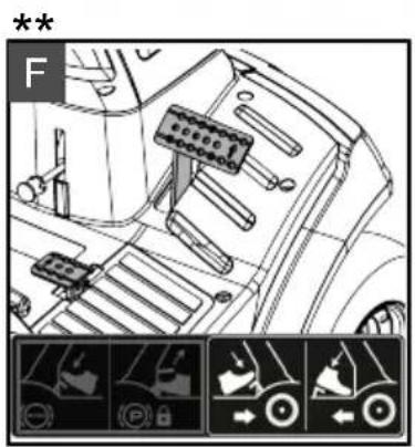
7.6.2.2 Reverse mowing with foot hydrostat transmission (21)
On engaging the mower mechanism, the pedal for reversing is limited to a maximum speed of 1.08 km/h. Up to this speed, reverse mowing can also be carried out at any time by depressing the reverse pedal.
- During forwards mowing:
■ Relieve the forwards pedal (21/1)
■ Depress the brake pedal (21/2) until the ride-on mower is stationary.
- Depress the reverse pedal (21/3).
NOTE If you engage the mower mechanism when reversing, the ride-on mower is automatically braked to 1.08 km/h and the reverse pedal is locked.
Enabling a higher speed when reverse mowing
For reverse mowing at full speed, the reverse pedal can be enabled – even during reverse mowing:
-
During reverse mowing, push the enable button (21/4) on the right-hand side of the steering column cover downwards.
-
Depress the reverse pedal and release the enable button:
The reverse pedal remains enabled at a speed in excess of 1.08 km/h. It can now be depressed to the end stop.
If the speed drops below 1.08 km/h (e.g. due to braking), the reverse pedal is automatically locked again.
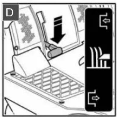
7.6.3 Switching off the mower mechanism
WARNING! Danger due to spinning blades! When the cutting blades are still spinning, they can cause laceration injuries to hands and feet! As a result, keep your hands and feet away from the cutters!
- To shut off the mower mechanism, pull the mower mechanism lever (03/D) out of the detent and push the lever completely downwards.
The mower mechanism can be shut off when the ride-on mower is stationary and also while it is moving.
WARNING! Risk of injury due to objects being thrown out! When crossing areas of gravel and crushed stone, objects can be drawn into the running mower mechanism and then thrown out.
■ Always switch off the mower mechanism if you are driving over surfaces other than lawns.
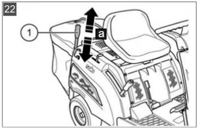
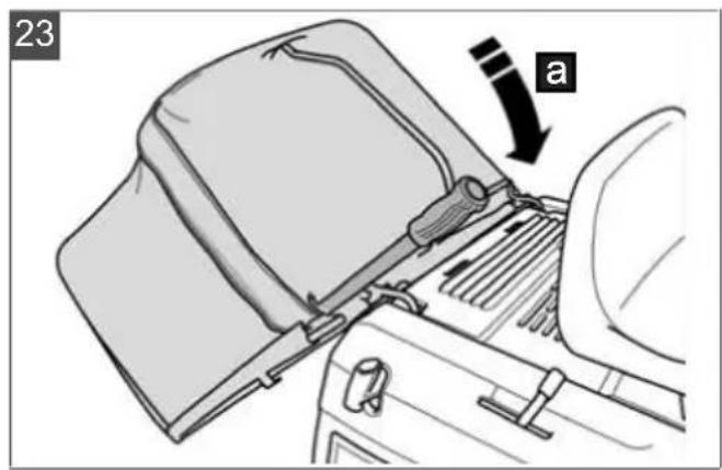
7.6.4 Emptying the grass catcher (22, 23)
NOTE An audible signal sounds when the grass catcher is full. The catcher should be emptied now if not before.
The ride-on mower is equipped with a manually actuated grass catcher with operating lever.
■ The grass catcher can be emptied from the operator's seat.
The engine cuts out if the grass catcher is lifted up or disconnected when the mower mechanism is switched on.
The mower mechanism cannot be switched on unless the grass catcher is engaged correctly.
Emptying the grass catcher with operating lever
- Pull the operating lever (22/1) out of the grass catcher (22/a).
- Push the lever in the direction of travel so that the grass catcher opens (23/a).
- Move the grass catcher backwards with the lever until the catcher engages.
7.6.5 Mowing interval
Please take into account that grass grows differently at different times. We recommend using a shorter interval between mowing during early spring. You can increase the mowing intervals as the growth rate of the grass begins to decline during the course of the year.
If you are unable to mow the grass for an extended period, you should initially select a higher cutting height setting, then re-mow two days later with a lower cutting height setting.
7.6.6 Mowing high grass
Mow with a higher cutting height adjustment when the grass is longer than normal or when it is wet. Then re-mow the grass with a lower, normal setting.
7.6.7 Cutting blade maintenance
Make sure that the cutting blade remains sharp for the entire mowing season to avoid shredding
or tearing the blades of grass. Shredded grass blades turn brown on the edges. This reduces their growth and leaves the lawn prone to diseases.
- Check the cutting blade for sharpness and signs of wear or damage after each use! If necessary please contact a service workshop.
If replacement is required, only use original manufacturer replacement blades.
8 CLEANING THE RIDE-ON MOWER
The ride-on mower must be cleaned regularly to ensure optimum function and a long service life.
Clean the ride-on mower and the grass catcher each time after use to remove adhering soiling.
Do not use a high-pressure cleaner for cleaning. The water jet from a high-pressure cleaner or a garden hose can damage the electrical system or bearings.
In particular, make sure that no water comes into contact with the engine, transmission and deflection pulleys, as well as the entire electrical system.

WARNING! Dangers when cleaning!
During all cleaning work:
■ Switch off the engine and remove the ignition key.
■ Remove the spark plug connector.
■ Protective devices removed for cleaning must be reinstalled afterwards.
■ DANGER OF BURNS: Do not clean the lawn tractor until it has cooled down. The engine, transmission and silencer get very hot!
■ DANGER OF LACERATIONS: When working on the cutters, pay attention to the sharp blades. In mowers with more than one blade, moving one cutter can cause the other to move as well!
8.1 Cleaning the grass catcher
NOTE Empty the grass catcher before cleaning as described. A full grass catcher is too heavy to be removed safely.
Removing the grass catcher
- Shut off the engine (see chapter 7.4 "Starting and shutting off the engine", page 38).
- Remove the grass catcher (see chapter 6.5 "Hooking in and removing the grass catcher (15)", page 37).
Cleaning the grass catcher
- Spray the inside and outside of the grass catcher with a water hose.
- Carefully remove solid, adhering soiling, e.g. with a brush.
Note: Take particular care not to damage the fabric on grass catchers with a fabric covering.
8.2 Cleaning the deck, engine and transmission
Do not use water or a high-pressure cleaner to spray down the engine or any of the bearing points (wheels, transmission, blade bearing).
Water penetrating the ignition system, carburettor and air filter can cause malfunctions. Water in the bearing points can lead to loss of lubrication, and thus cause irreparable damage to the bearings.
Use a cloth, hand brush, long-handled paintbrush or similar for removing dirt and grass residues.
IMPORTANT! Damage to the electrical system by penetrating water! When cleaning the ride-on mower with water, make sure that no water enters the electrical system!
8.3 Cleaning the discharge channel
Regular cleaning ensures that the cutting height adjustment can be moved easily.
8.4 Cleaning the mowing system
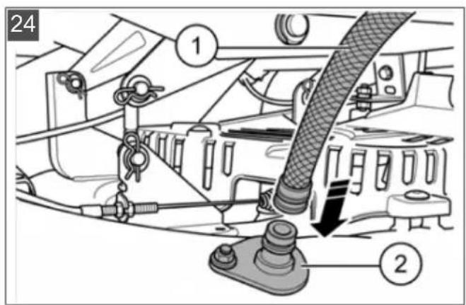
There are connections for a 1/2" water hose coupling on the mower deck. The mowing system can be cleaned by connecting a water hose.
The grass catcher must be mounted during the cleaning process.
- Connect the water hose (24/1) to the cleaning fitting (24/2) and turn on the water.
- Start the engine and set it to a medium engine speed (see chapter 7.4 "Starting and shutting off the engine", page 38).
- Lower the mower mechanism to the lowest cutting height (see chapter 5.5 "Operating the mower mechanism (09, 10)", page 35).
- Switch on the mower mechanism.
- The mowing system will be cleaned within a few minutes.
- Switch off the mower mechanism.
- Switch off the engine.
-
Turn off the water and disconnect the hose (24/1).
-
Start the engine again and allow the mower mechanism to run for a few more minutes in order to fling out the water.
-
Clean the grass catcher (see chapter 8.1 "Cleaning the grass catcher", page 42).
9 MAINTENANCE

WARNING! Dangers during maintenance!
During all maintenance work:
■ Switch off the engine and remove the ignition key.
■ Remove the spark plug connector.
■ Protective devices removed for maintenance must be reinstalled afterwards.
■ DANGER OF BURNS: Do not work on the ride-on mower until it has cooled down. The engine, transmission and silencer get very hot!
■ DANGER OF LACERATIONS: When working on the cutters, pay attention to the sharp blades. In mowers with more than one blade, moving one cutter can cause the other to move as well.
■ Parts are only allowed to be renewed by genuine spare parts.
If in doubt, always visit a specialist workshop or contact the manufacturer.
9.1 Maintenance schedule
The following jobs are allowed to be carried out by the user independently. All other maintenance, service and repair work must be carried out in an authorised service workshop.
In addition, please also comply with the recommended annual lubrication tasks as indicated in the lubrication plan.
| Activity Before | each use | After each use | After the first 5 hours | Every 25 operating hours | Every 50 operating hours | Each time be- fore put- ting into storage |
| Checking the engine oil lev- el *) | X | |||||
| Changing the engine oil *) | X | X | ||||
| Cleaning the air filter *) | X | |||||
| Replacing the air filter *) | X | |||||
| Checking the spark plug *) | X | |||||
| Checking the brake (test braking on a straight path) | X | |||||
| Check the tyre pressure X | ||||||
| Check the mowing blades X | ||||||
| Checking for loose parts X X | ||||||
| Checking V-belts (visual check) | X | |||||
| Activity Before | each use | After each use | After the first 5 hours | Every 25 operating hours | Every 50 operating hours | Each time before putting into storage |
| Cleaning the ride-on mower X | ||||||
| Cleaning the air intake grille on the engine* | X | |||||
| Clean the transmission to remove grass and mowing residues | X | X |
)* Refer to the operating instructions of the engine manufacturer
NOTE It may be necessary to shorten the maintenance intervals compared to those stated in the table above in case of severe loading and at high temperatures.
9.2 Lubricating plan
To ensure that moving parts can move freely, we recommend lubricating the following points at least once a year.
Use a cloth to clean all points to be lubricated before greasing or spraying. Do not use water, so as to avoid possible corrosion.
Lubrication points:
■ Spray oil onto the bearings of the front axle on the frame.
Pivoting and bearing points: Lubricate all movable pivoting and bearing points.
NOTE The front and rear wheels must be removed for greasing the axles and bearings.
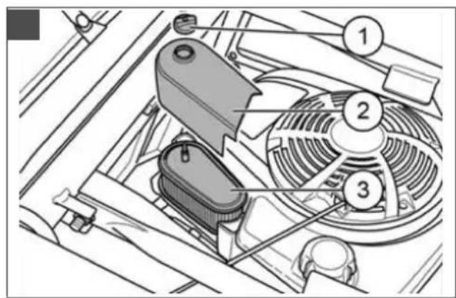
9.3 Cleaning the air filter (11, 25)
The air filter must be cleaned according to the maintenance schedule. To remove the air filter proceed as follows:
IMPORTANT! Risk of property damage!
Engine components can be damaged due to dirt ingress when cleaning the air filter!
■ Make sure that the area surrounding the air filter is clean and that no dirt gets into the intake port of the engine when the air filter is pulled off.
- Switch off the engine and remove the ignition key.
-
Wait until the engine has cooled down.
-
Fold the seat (11/1) forwards and open the cover (11/2) to the engine compartment (11/a).
- Unscrew the mounting screw (25/1).
- Pull the air filter cover (25/2) upwards off the guide.
- Pull the air filter (25/3) off the guide.
- Clean the air filter or renew it if necessary.
- Reinstall the air filter in reverse order and tighten the mounting screw (25/1) again.
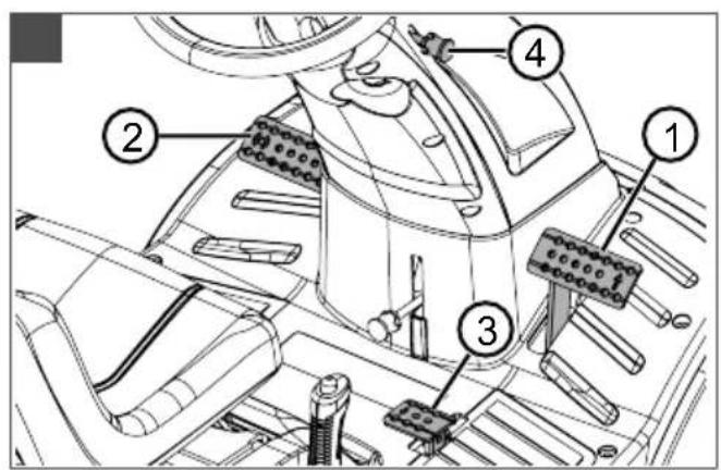
9.4 Checking the spark plug (26, 27, 28)
The spark plug must be checked according to the maintenance schedule and exchanged if necessary.
Spare spark plug:
R7-63.8 A: F7RTC – Art. no. 418577
■ R7-62.5, RC7YC (Champion) – Art. no.
R7-65.8 HD: 493413
Please note that the spare spark plug used by the equipment manufacturer may differ from the engine manufacturer's specifications due to specific applications.
NOTE For more detailed information, please refer to the separate operating instructions for the engine.
NOTE All work on the spark plug is only allowed to be carried out when the engine is stopped and has cooled down fully.
NOTE Always replace the old spark plug with a new spark plug with the same characteristics.
-
Remove the grass catcher (see chapter 6.5 "Hooking in and removing the grass catcher (15)", page 37).
-
Remove the mounting screws (26/1) from the rear fairing.
-
Open the rear fairing:
■ Fold the rear fairing half way open.
For subsequent assembly, note how the cables are connected to the fill level sensor, and remove them.
■ Fold the rear fairing open completely.
-
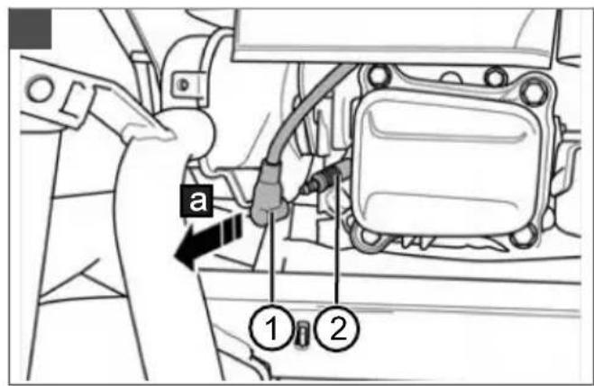
Remove the spark plug connector (27/1) from the spark plug (27/2) (27/a).
-
Unscrew the spark plug with the supplied spanner (28/1) (28/a).
-
Check the electrode gap (A) and reset it if necessary (28).
Note: The correct electrode gap can be found in the operating instructions from the engine manufacturer.
-
Screw the spark plug in to the end stop with the supplied spanner and tighten it.
-
Push the spark plug connector back onto the spark plug.
-
Close the rear fairing again:
■ Connect the cables to the fill level sensor.
■ Fold the rear fairing closed.
■ Screw in the mounting screws (26/1).
- Hook the grass catcher in again (see chapter 6.5 "Hooking in and removing the grass catcher (15)", page 37).
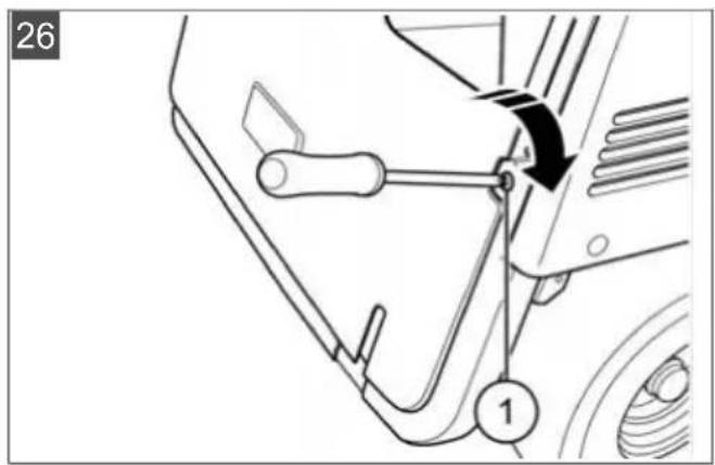
9.5 Adjusting the Bowden cable for the mower mechanism (29)
WARNING! Risk of injury! Any work on the mower mechanism must only be carried out when the engine is switched off!
If the mower mechanism can no longer be switched on or off again, the switching mechanism on the Bowden cable can be adjusted.
NOTE If the mower mechanism cannot be switched on or off at all, have your ride-on mower checked and repaired by your customer service workshop.
■ To adjust the Bowden cable (29/1), loosen the two nuts (29/2) and (29/3).
If the mower mechanism can no longer be switched on correctly, loosen the nut (29/3) and adjust the Bowden cable (29/1) with the nut (29/2) until the mower mechanism can be switched on correctly again.
If the mower mechanism can no longer be switched off correctly, loosen the nut (29/2) and adjust the Bowden cable (29/1) with the nut (29/3) until the mower mechanism can be switched off correctly again.
9.6 Adjusting the mower mechanism (30)
The cutting height setting can be adjusted if it is no longer correct as a result of wear or because you have changed the tyres.
-
Park the ride-on lawnmower on a straight and level surface.
-
Set the cutting height adjustment (09/2) to the lowest position.
-
Release the locking pin (30/2) from the holding pin (30/3).
-
Pull the holding pin (30/3) out of the mower mechanism and the adjusting pin (30/1).
-
Adjust the cutting height accordingly with the adjusting pin (30/1).
-
Push the holding pin (30/3) back through the adjusting pin (30/1) and the mower mechanism, and secure the holding pin again using the locking pin (30/2).
The correct setting of the mower mechanism – 25 mm at the front and 35 mm at the rear – is measured at the lowest cutting height setting. These dimensions refer to the lower edge of the mower mechanism to the ground.
9.7 Starter battery
The ride-on mower scope of supply does not include a charger for the starter battery.
Precise battery designation: see battery box. The starter battery is located under the engine cover. The starter battery is always supplied from the factory pre-charged.
WARNING! Danger if the starter battery is not handled correctly! The following points must be complied with to avoid the dangers arising from incorrect handling of the battery!
- Do not store the starter battery in the immediate vicinity of naked flames, do not burn it or place it on heaters. Risk of explosion.
■ Store the starter battery in a cool, dry room (10 - 15 °C) over the winter. Avoid storing at temperatures below the freezing point.
Do not leave the starter battery without charge for a long period. If the starter battery is not used for a long period, it should be charged using a suitable charger.
- Do not smash the starter battery. The electrolyte (sulphuric acid) causes chemical burns to the skin and clothing – immediately rinse away with plenty of water.
- Keep the starter battery clean. Only wipe clean with a dry cloth. Do not use water, petrol, thinners or similar for this purpose.
- Keep the connection terminals clean and grease them with terminal grease.
■ Do not short-circuit the connection terminals.
Charging the starter battery
Charging is required:
■ Before putting into storage before the winter break.
If the machine will not be used for a long time (longer than 3 months).
WARNING! Danger if the starter battery is not charged correctly! The charging current of the charger must not exceed 5 A, and the charging voltage can only be max. 14.4 V. Risk of explosion of the starter battery if the charging current is more powerful! Always remove the ignition key before starting work on the battery.
We recommend charging this maintenance-free, gas-tight starter battery using a specifically suitable charger (which can be obtained through retail outlets).
Comply with the operating instructions of the charger manufacturer before and during charging of the starter battery.
⚠️ CAUTION! Danger of a short circuit! To avoid a short circuit, always disconnect the negative cable (-) of the battery first, and reconnect it last! Always remove the ignition key before starting work on the battery!
- Remove the ignition key.
- Open the bonnet (01/7).
- Connect the charger terminals to the connection terminals of the battery.
NOTE Check the polarity:
■ Red terminal = positive terminal (+)
■ Black terminal = negative terminal (-)
- Connect the charger to the mains and switch it on.
10 TRANSPORT
When transporting the ride-on mower using transport equipment (e.g. passenger car trailer), the mower mechanism must be supported from below to reduce the strain on the mower mechanism mounting.
During transport, make sure that the means of transport has a sufficient load capacity and that the ride-on mower is suitably secured.
11 STORAGE
Protection against weather effects
The ride-on mower should be parked where it is protected against the effects of weather, especially moisture, rain and lengthy exposure to direct sunlight. Particularly the UV radiation contained in sunlight can cause plastic parts to fade, and damage them, in the event of long-term exposure.
Parking the ride-on mower
Never store the ride-on mower with fuel in the tank inside a building in which fuel vapours may possibly come into contact with naked flames or sparks. Only park the ride-on mower in rooms that are suitable for storing motor vehicles.
Long periods of storage
If possible, the ride-on mower should not be stored for long periods, e.g. over winter, with a full fuel tank. The fuel can evaporate.
Before long-term storage, the fuel should be drained from the tank and the carburettor in order to avoid any build-up of deposits, which could result in problems when starting. Please contact your specialist workshop for advice.
12 HELP IN CASE OF MALFUNCTION
CAUTION! Risk of injury. Sharp-edged and moving appliance parts can lead to injury.
■ Always wear protective gloves during maintenance, care and cleaning work!
NOTE For malfunctions that are not listed in this table or that you cannot resolve yourself, please contact our customer service.
| Malfunction Cause Remedy | |||
| Engine does not start. Lack of fuel. Fill tank; check tank bleeding; check fuel filter. | |||
| Starter does not work. Starter battery flat or weakly charged. | Charge starter battery. | ||
| Sit on operator's seat correctly; switch defective. | |||
| Press brake pedal down fully. | |||
| Switch off mower mechanism. | |||
| Check fuse, replace if necessary. | |||
| Engine is losing power. Grass too long or too wet. Correct the cutting height; make clearance for mower mechanism by moving back a short distance. | |||
| Clean discharge channel/mower deck. Stop engine and take out ignition key! | |||
| Air filter contaminated. Clean air filter. | |||
| the setting checked (customer service workshop). | |||
| Blades severely worn down. Replace blades (customer service workshop). | |||
| Driving speed too fast. Reduce driving speed. | |||
| Ride-on mower vibrates extensively. | Mower mechanism is damaged. Check mower mechanism (customer service workshop). | ||
| Malfunction Cause Remedy | |||
| Rough cut. Blade worn, blunt. Renew or regrind blade. Reground blades must be rebalanced (customer service workshop)! | |||
| Correct cutting height. Correct the cutting height. | |||
| Engine speed too slow. Set maximum engine speed. | |||
| Driving speed too fast. Reduce driving speed. | |||
| Different tyre pressure at wheels. Inflate to correct air pressure. Read off correct tyre pressure on tyre. | |||
| Grass catcher does not fill up. | Cutting height set too low. Correct the cutting height. | ||
| Grass is wet – it is too heavy to be transported by air stream. | Mow at a later time when lawn has dried out. | ||
| Blades severely worn down. Change blade. (Customer service work-shop) | |||
| Grass in lawn too tall. Mow grass twice:■ 1st pass: max. cutting height■ 2nd pass: desired cutting height. | |||
| Fabric bag blocked – no air throughput. | Clean fabric bag. | ||
| Discharge channel/mower deck contaminated. | Clean discharge channel/mower deck. | ||
| Travel drive, brake, clutch and mower mechanism. | Only have the check performed in a customer service workshop! | ||
13 TECHNICAL DATA
| Ride-on mower R7-62.5 R7-63.8 A R7-65.8 HD | |||
| Item no. 127306 | 127486 | 127487 | |
| Engine | |||
| Name | B&S series 950 E | AL-KO Pro 225 | B&S series 950 E |
| Type | 14B9 1P75F | 14B9 | |
| Operating mode | Petrol | ||
| Engine starting | E-start/manual start | ||
| Engine speed [rpm] | 3000 | ||
| Engine output [kW] | 3.97 | 4.2 | 3.97 |
| Displacement [cm3] | 223 | 224 | 223 |
| Fuel tank capacity [litres] | 1.1 | 1.4 | 1.1 |
| Ride-on mower | |||
| Max. driving speed [km/h] at 3,000 rpm (forwards / backwards) | 4.5 / 1.4 | 4.5 / 1.4 | 5.9 / 3.0 |
| Transmission Tecumseh (4/1) Tecumseh (4/1) Hydro Gear T1 | |||
| Gear speeds (km/h): Stepless | |||
| ■ 1st gear, forwards 1.5 1.5 – | |||
| ■ 2nd gear, forwards 2.5 2.5 – | |||
| ■ 3rd gear, forwards 3.5 3.5 – | |||
| ■ 4th gear, forwards 4.5 4.5 – | |||
| ■ Reverse gear 1.4 1.4 – | |||
| Weight [kg] 125 125 | 125 | ||
| Mowing circle [cm] | 125 | ||
| Steering | Direct | Direct | Indirect (steering box) |
| Grass catcher | |||
| Catcher capacity [litres] | 130 | ||
| Grass carrier emptying | Mechanical (telescopic lever) | ||
| Grass catcher fill-level indicator | No | Yes | Yes |
| Cutting blade | |||
| Number of cutting blades | 1 | ||
| Cutting width [cm] | 61.6 | ||
| Blade brake clutch | Mechanical belt clutch | ||
| Cutting height [mm] | 25 – 75 | ||
| Cutting height adjustment | 4-stage | ||
| Tyres | |||
| Tyre size, front [inches] | 11x4.0-5 | ||
| Tyre size, rear [inches] | 13x5.0-6 | ||
| Tyre pressure [bar] | 1.0 – 1.4 | ||
| Maximum noise and vibration values [1] | |||
| Measured sound pressure level at the operator's ear ISO 5395-1 LpA [dB(A)] | 92.6 | 83.1 | 82.1 |
| ■ Measurement inaccuracy K for LpA [dB(A)] | 2 | 3 | 3 |
| Measured sound power level LwA [dB(A)] | 93.70 | 94.45 | 93.70 |
| ■ Measurement inaccuracy K for LwA [dB(A)] | 1.2 | 1.17 | 1.11 |
| Guaranteed sound power level LwA [dB(A)] | 98 | 98 | 98 |
| Ride-on mower R7-62.5 R7-63.8 A R7-65.8 HD | |||
| Vibration value ahw [m/s ^2 ] according to DIN EN ISO 5395-1Whole body vibration / hand-arm vibration | 2 / 3.5 1.18 / 2.31 (left) / 2.08 (right) | 1.48 / 3.45 (left) / 2.66 (right) | |
| Measurement inaccuracy K for ahw 2 1.5 1.5 | |||
[1] The vibration value may change depending on use and the tools employed, and may also exceed the specified value. It is necessary to define safety measures to protect the operator that are based on an estimate of the vibration load during actual conditions of use (this must consider all portions of the operating cycle, for example times when the machine is switched off and times when it is switched on but running without load).
14 AFTER-SALES/SERVICE
In the event of questions of warranty, repair or spare parts, please contact your nearest AL-
KO Service Centre. These can be found on the Internet at:
www.al-ko.com/service-contacts
15 GUARANTEE
We will resolve any material or manufacturing faults on the appliance during the legal warranty period for claims relating to faults, in accordance with our choice either to repair or replace. The legal warranty period is determined by the legislation of the country in which the appliance was purchased.
Our warranty promise applies only if:
These operating instructions are heeded
■ The appliance is handled correctly
■ Original spare parts have been used
The warranty becomes void in the case of:
■ Unauthorised repair attempts
■ Unauthorised technical modifications
Non-intended use
The guarantee excludes:
■ Paint damage that can be attributed to normal wear and tear
■ Wear parts that are marked with a frame xxxxxx (x) on the spare parts card
■ Internal combustion engines (these are covered by the guarantee provisions of the corresponding engine manufacturers)
The guarantee period commences with purchase by the first end user. The date on the proof of purchase is decisive. In the event of a guarantee claim, please take this guarantee declaration and the original proof of purchase, and contact your dealer or the nearest authorised customer service centre. This statement does not affect the purchaser's statutory claims for defects against the vendor.
VERTALING VAN DE ORIGINELE GEBRUIKERSHANDLEIDING
Inhoudsopgave
2 PRODUCTOMSCHRIJVING
R7-63.8 A: F7RTC - Cod. art. 418577
■ R7-62.5, RC7YC (Champion) - Cod.
R7-65.8 HD: art. 493413
9.7 Akumulatorski zaganjalnik
14 SERVISNA SLUŽBA/SERVIS
www.al-ko.com/service-contacts
15 GARANCIJA
R7-62.5, RC7YC (Champion) – br. art. R7-65.8 HD: 493413
Imajte na umu da se zamjenska svjećica koju upotrebljava proizvođač uređaja može razlikovati od podataka koje daje proizvođač motora zbog specifičnih primjena.
H NAPOMENA Za detaljnije informacije proučite odvojene upute za uporabu za motor.
www.al-ko.com/service-contacts
15 JAMSTVO
Možebitne greške u materijalu ili proizvodnji na uređaju uklonit ćemo tijekom zakonskoga roka zastare za jamstvo na nedostatke prema vlastitom izboru popravljanjem ili zamjenskom dostavom. Rok zastare određuje se prema pravu države u kojoj je uređaj kupljen.
www.al-ko.com/service-contacts
15 ГАРАНЦИЈА
www.al-ko.com/service-contacts
15 ZÁRUKA
www.al-ko.com/service-contacts
15 ZÁRUKA
www.al-ko.com/service-contacts
15 GARANTI
R7-63.8 A: F7RTC – art.-nr 418577
R7-62.5, RC7YC (Champion) – art.-nr
R7-65.8 HD: 493413
9.5 Stille inn vaier for klippeaggregat (29)
9.6 Stille inn klippeaggregat (30)
www.al-ko.com/service-contacts
15 GARANTI
www.al-ko.com/service-contacts
15 GARANTIJA
R7-63,8 A: F7RTC - Apt. № 418577
R7-62.5, RC7YC (Champion) – Apt. №
R7-65.8 HD: 493413
www.al-ko.com/service-contacts
15 ГАРАНТИЯ
Imported by: AL-KO Gardentech UK Ltd, Murray way, Wincanton, Somerset, BA9 9RS / UK | +44 (0) 1963
828055
shop.uk@al-ko.com | www.alko-garden.uk
AL-KO Service: www.al-ko.com/service-contacts


- Inhaltsverzeichnis
- ABOUT THESE INSTRUCTIONS FOR USE
- Symbols on the title page
- Symbol Meaning
- Legends and signal words
- PRODUCT DESCRIPTION
- Designated use
- Possible foreseeable misuse
- Safety and protective devices
- Symbols on the appliance
- Product overview (01, 02)
- SAFETY INSTRUCTIONS
- UNPACKING AND ASSEMBLING THE RIDE-ON MOWER
- CONTROLS
- Controlling the engine speed (03)
- Ignition lock (04)
- Brake/clutch pedal (05), brake pedal (06)
- Brake
- Parking brake
- Transmission operation [driving speed]
- Operating the manual transmission (03, 05, 07)
- Starting the engine
- Selecting a gear
- Operating the foot hydrostat transmission (03, 08)
- Moving off
- Increasing the speed
- Operating the mower mechanism (09, 10)
- Setting the cutting height
- Switching on the mower mechanism
- START-UP
- Checking the mower mechanism
- Filling with oil (11, 12)
- Filling with fuel (11, 13)
- Filling the tank
- Check tyre pressure (14)
- Hooking in and removing the grass catcher (15)
- Hooking in the grass catcher
- Remove the grass catcher
- Checking the safety devices
- Checking the brake contact switch (03, 04)
- Checking the mower mechanism contact switch
- Checking the seat contact switch (16)
- Checking the grass catcher contact switch (17, 18)
- Visual inspection of the mower mechanism and belt covers
- Fundamental preparatory measures
- Use of accessories
- Pushing the ride-on mower (03, 19)
- CAUTION! Danger when pushing on
- Pushing with manual transmission
- Pushing with foot hydrostat transmission
- Starting and shutting off the engine
- Starting the motor
- Starting the engine (electrically):
- Starting the engine (with cable starter):
- Switch off the engine
- Driving with the ride-on mower
- Starting off and stopping with manual transmission
- Starting off and stopping with foot hydrostat transmission
- Preparing to drive at temperatures below 10 °C
- Driving and mowing on slopes
- Mowing with the ride-on mower
- Switching on the mower mechanism
- Mowing in reverse
- Reverse mowing with manual transmission
- Reverse mowing with foot hydrostat transmission (21)
- Enabling a higher speed when reverse mowing
- Switching off the mower mechanism
- Emptying the grass catcher (22, 23)
- Emptying the grass catcher with operating lever
- Mowing interval
- Mowing high grass
- Cutting blade maintenance
- CLEANING THE RIDE-ON MOWER
- WARNING! Dangers when cleaning!
- Cleaning the grass catcher
- Removing the grass catcher
- Cleaning the grass catcher
- Cleaning the deck, engine and transmission
- Cleaning the discharge channel
- Cleaning the mowing system
- MAINTENANCE
- WARNING! Dangers during maintenance!
- Maintenance schedule
- Lubricating plan
- Cleaning the air filter (11, 25)
- IMPORTANT! Risk of property damage!
- Checking the spark plug (26, 27, 28)
- Spare spark plug:
- Adjusting the Bowden cable for the mower mechanism (29)
- Adjusting the mower mechanism (30)
- Starter battery
- Charging the starter battery
- TRANSPORT
- STORAGE
- Protection against weather effects
- Parking the ride-on mower
- Long periods of storage
- HELP IN CASE OF MALFUNCTION
- AFTER-SALES/SERVICE
- GUARANTEE
- VERTALING VAN DE ORIGINELE GEBRUIKERSHANDLEIDING
- Inhoudsopgave
- PRODUCTOMSCHRIJVING
- Akumulatorski zaganjalnik
- SERVISNA SLUŽBA/SERVIS
- GARANCIJA
- JAMSTVO
- ГАРАНЦИЈА
- ZÁRUKA
- GARANTI
- Stille inn vaier for klippeaggregat (29)
- Stille inn klippeaggregat (30)
- GARANTIJA
- ГАРАНТИЯ
Brand : AL-KO
Model : Solo R765.8 HD
Category : Tractor