
Solo T 20105.6 HD V2 Premium - Tractor AL-KO - Free user manual and instructions
Find the device manual for free Solo T 20105.6 HD V2 Premium AL-KO in PDF.

| Product type | Riding mower (garden tractor) |
| Brand | AL-KO |
| Model | Solo T 20105.6 HD V2 Premium |
| Category | Tractor |
| Fuel | Unleaded petrol (min. 91 RON) |
| Engine | 4-stroke petrol |
| Transmission | Hydrostatic with pedal (forward/reverse) |
| Collection bag capacity | 310 litres |
| Blade clutch | Electromagnetic |
| Bag emptying | Electric (switch) or manual (lever depending on version) |
| Maximum slope | 10° (18%) |
| Recommended tire pressure | 1 bar |
| Cutting height adjustment | Multi-level lever |
| Safety devices | Brake, seat, cutting deck, collection bag, discharge chute switches |
| Cleaning | After each use, not with high-pressure cleaner |
| Regular maintenance | Check engine oil, air filter, spark plug, blade, belt, tire pressure |
| Warranty | Against manufacturing defects (statutory period) |
| Starting | Ignition key with integrated choke or button |
| Brake | Brake pedal with parking brake (lever) |
Frequently Asked Questions - Solo T 20105.6 HD V2 Premium AL-KO
User questions about Solo T 20105.6 HD V2 Premium AL-KO
0 question about this device. Answer the ones you know or ask your own.
Ask a new question about this device
Download the instructions for your Tractor in PDF format for free! Find your manual Solo T 20105.6 HD V2 Premium - AL-KO and take your electronic device back in hand. On this page are published all the documents necessary for the use of your device. Solo T 20105.6 HD V2 Premium by AL-KO.
USER MANUAL Solo T 20105.6 HD V2 Premium AL-KO
natural_image
Technical line drawing of a grassing machine (no text or symbols present)


Inhaltsverzeichnis
Deutsch 10
English....30
Nederlands 50
Français....70
Español 92
Italiano....114
Slovenščina 134
Hrvatski....153
Српски....173
Polski....194
Česky 216
Slovenská 236
Magyarul....256
Dansk 276
Svensk....295
Norsk 314
Suomi 333
Eesti 352
Lietuvių 371
Latviešu 391
български 411
Русский 434
Україна....457
Ελληνικά 478
Македонски ....500
Türkçe 523
© 2019
AL-KO KOBER GROUP Kötz, Germany
This documentation or excerpts therefrom may not be reproduced or disclosed to third parties without the express permission of the AL-KO KOBER GROUP.
natural_image
Technical line drawing of a mechanical device with a rotating wheel and side-mounted components (no text or symbols)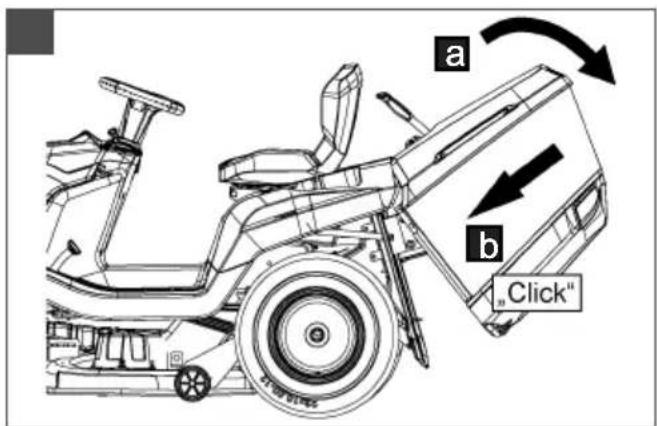
natural_image
Technical line drawing of a tractor with wheel rim and side-mounted frame (no text or symbols)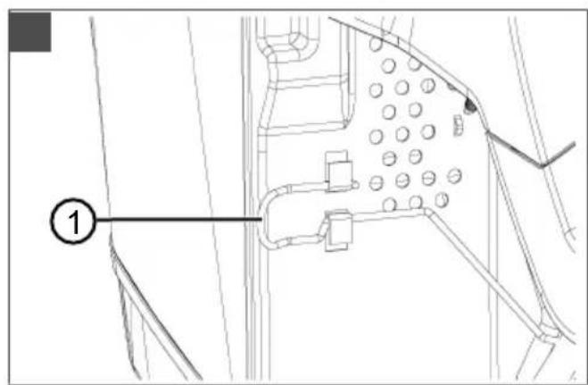
natural_image
Technical line drawing of a mechanical assembly with circular components and a ladder (no text or symbols)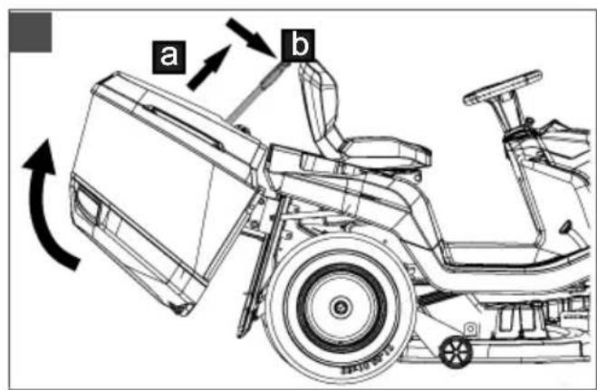

natural_image
Technical line drawing of a mechanical assembly with no visible text or symbols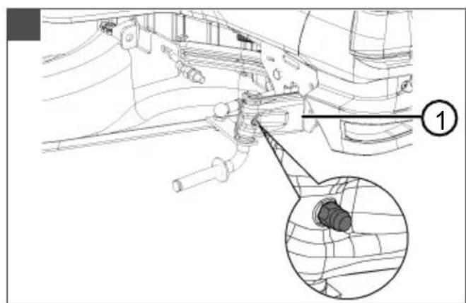
natural_image
Technical diagram of a mechanical assembly with an inset showing a component detail (no text or symbols present)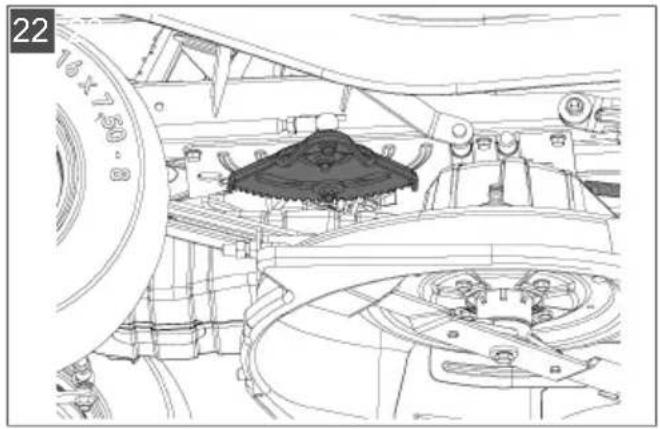
natural_image
Technical line drawing of a mechanical assembly with no visible text or symbols
natural_image
Technical line drawing of a cleaning or maintenance vehicle with visible components and structural details (no text or symbols)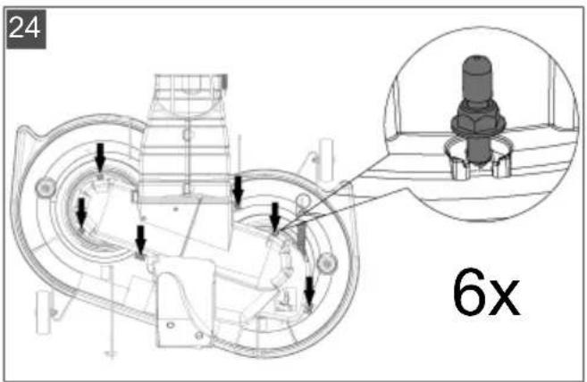
natural_image
Technical line drawing of a mechanical housing assembly with cables and components (no text or symbols)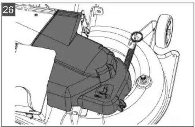
natural_image
Technical diagram of a mechanical assembly with no visible text or symbols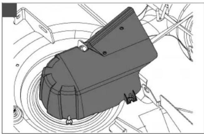
natural_image
Technical line drawing of a mechanical component with concentric circular features (no text or symbols)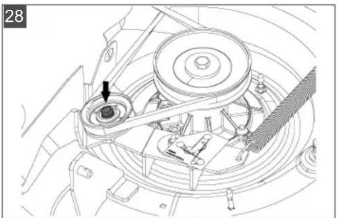
natural_image
Technical line drawing of a mechanical assembly with no visible text or symbols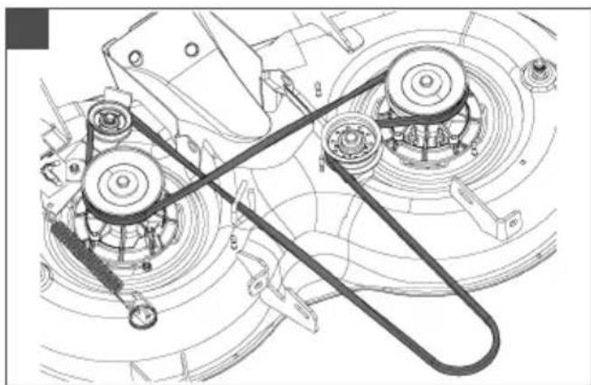
natural_image
Mechanical assembly diagram showing pulleys, gears, and linkages (no text or labels)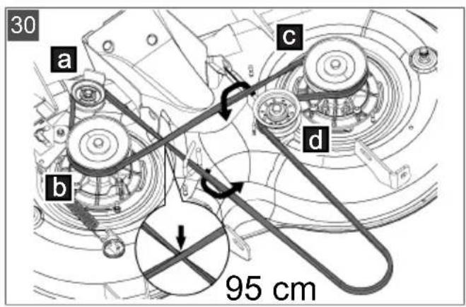
natural_image
Technical line drawing of a tractor's front wheel and side arm (no text or symbols)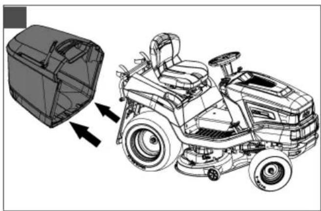
natural_image
Technical line drawing of a tractor with gear and control panel, showing mechanical components and directional arrows (no text or symbols)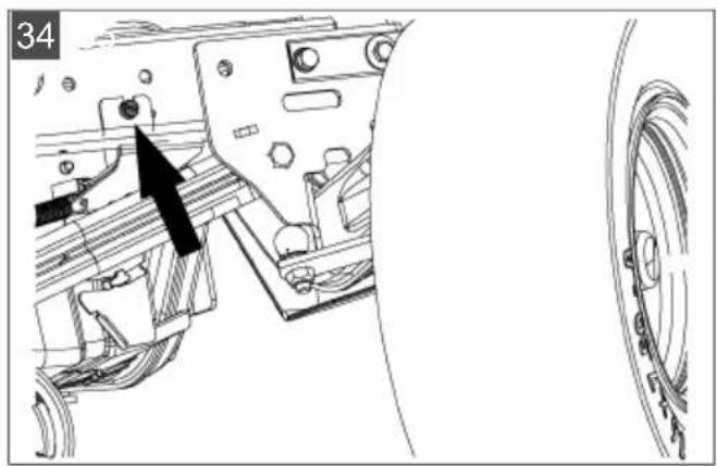
natural_image
Technical line drawing of a mechanical assembly with a black arrow pointing to a component (no text or symbols present)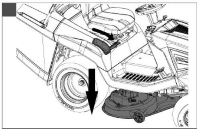
natural_image
Technical line drawing of a vehicle's front wheel assembly with a mounted lawn mower (no text or symbols)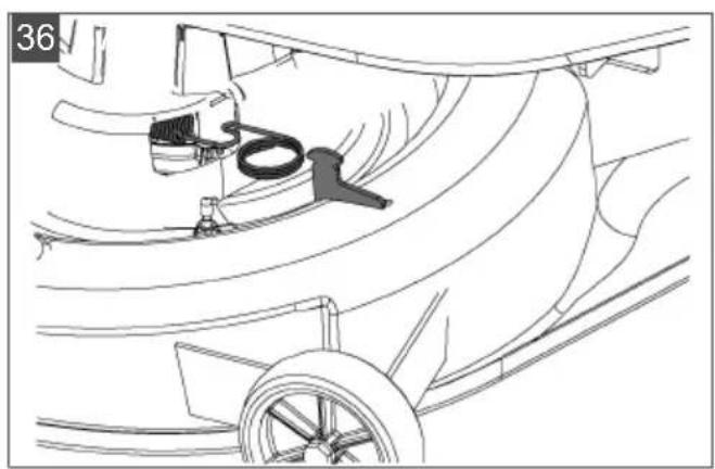
natural_image
Technical line drawing of a ship's hull with visible hull, hull, and wheel (no text or symbols)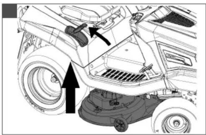
natural_image
Technical line drawing of a vehicle's front wheel assembly with mounting bracket and tire (no text or symbols)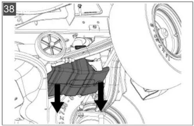
natural_image
Technical line drawing of a mechanical assembly with springs and levers (no text or symbols)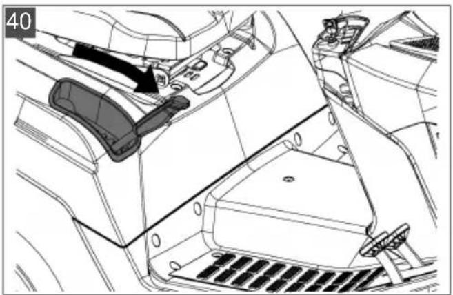
natural_image
Technical line drawing of a car interior showing dashboard, seatbelt, and dashboard components (no text or symbols)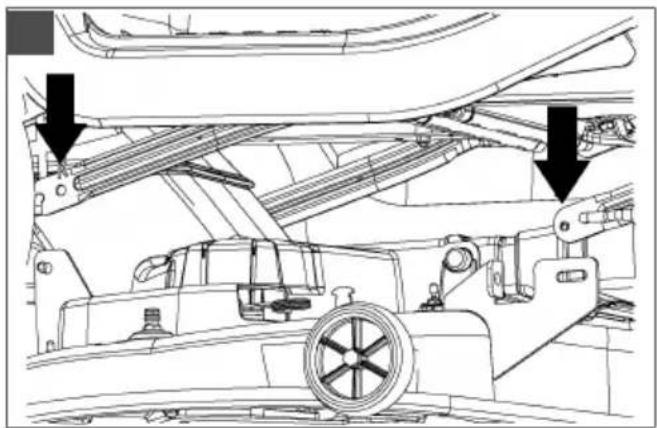
natural_image
Technical line drawing of a ship's internal structure showing structural components and two downward arrows indicating specific parts (no text or symbols present)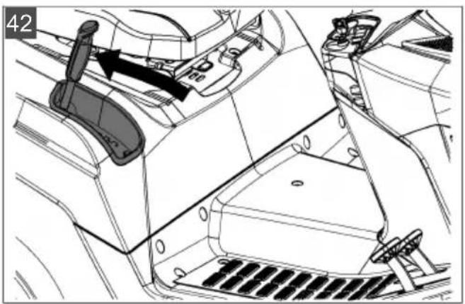
natural_image
Interior view of a vehicle showing steering wheel, dashboard, and gear shift (no text or symbols)1 About these instructions for use .... 31
1.1 Symbols on the title page.... 31
1.2 Legends and signal words ...... 31
2 Product description 31
2.1 Designated use 31
2.2 Possible misuse .... 31
2.3 Symbols on the appliance .... 32
2.4 Safety and protective devices .... 32
2.5 Product overview (01) 32
3 Safety instructions 32
4 Unpacking and assembling the tractor .... 33
5 Controls 33
5.1 Standard dashboard (02) 33
5.2 Dashboard with display (03)...... 33
5.2.1 Function keys and display 34
5.2.2 Pilot lights 34
5.3 Brake and clutch pedal (05) 35
5.4 Transmission operation (driving speed) (04).... 35
5.5 Foot hydrostat transmission (04, 05).. 35
5.6 Operating the mower mechanism (06).... 35
6 Start-up 35
6.1 Checking the mower mechanism ..... 36
6.2 Oil fill 36
6.3 Filling with fuel (09) 36
6.4 Checking the tyre pressure 36
6.5 Fitting the grass catcher (10 - 13) ..... 36
6.6 Checking the safety devices .... 37
6.6.1 Checking the brake contact switch.... 37
6.6.2 Checking the mower mechanism contact switch 37
6.6.3 Checking the seat contact switch 37
6.6.4 Checking the grass catcher contact switch.... 37
6.6.5 Checking the discharge channel contact switch 37
7 Operating the tractor 37
7.1 Fundamental preparatory measures .. 37
7.2 Use of accessories 38
7.3 Pushing the lawn tractor (15, 16)...... 38
7.4 Starting and stopping the engine..... 38
7.5 Driving with the tractor.... 38
7.5.1 Preparing to drive at temperatures below 10 °C.... 38
7.5.2 Driving with the foot hydrostat transmission.... 39
7.5.3 Driving with cruise control 39
7.5.4 Driving and mowing on slopes ..... 39
7.5.5 Mowing with the lawn tractor...... 39
8 Cleaning the lawn tractor.... 41
8.1 Cleaning the grass catcher.... 41
8.2 Cleaning the deck, engine and transmission.... 41
8.3 Cleaning the discharge channel (18).. 41
9 Maintenance.... 42
9.1 Maintenance schedule.... 42
9.2 Lubricating plan 42
9.3 Wheel change.... 43
9.4 Starter battery.... 43
9.5 Removing the mower mechanism ..... 44
9.6 Renewing the V-belt 44
10 Transport.... 44
11 Storage.... 44
12 Help in case of malfunction 45
12.1 Fault and fault rectification error shown on display 47
13 Guarantee 49
1 ABOUT THESE INSTRUCTIONS FOR USE
The German version is the original operating instructions. All additional language versions are translations of the original operating instructions.
■ Always safeguard these operating instructions so that they can be consulted if you need any information about the appliance.
■ Only pass on the appliance to other persons together with these operating instructions.
■ Comply with the safety and warning information in these operating instructions.
The lawn tractors are supplied with different levels of equipment. Please note that the illustrations may differ somewhat from the original. Please contact a specialist workshop or the manufacturer if you encounter difficulties in following the descriptions.
■ Comply with the enclosed installation instructions and the operating instructions for the petrol engine.
1.1 Symbols on the title page
Symbol Meaning

It is essential to read through these operating instructions carefully before start-up. This is essential for safe working and trouble-free handling.

Operating instructions

Never operate the petrol powered device in the vicinity of open flames or heat sources.
1.2 Legends and signal words
⚠️ DANGER! Denotes an imminently dangerous situation which will result in fatal or serious injury if not avoided.
WARNING! Denotes a potentially dangerous situation which can result in fatal or serious injury if not avoided.
CAUTION! Denotes a potentially dangerous situation which can result in minor or moderate injury if not avoided.
IMPORTANT! Denotes a situation which can result in material damage if not avoided.
NOTE Special instructions for ease of understanding and handling.
2 PRODUCT DESCRIPTION
Lawn tractors with rear discharge are manufactured in different versions. When reading the following descriptions in these instructions for use, make sure you are referring to the appropriate description for your lawn tractor.
Features of your lawn tractor:
■ Transmission: Foot hydrostat
■ Blade brake clutch: electromagnetic
Grass catcher capacity: 310 l
■ Grass catcher emptying: electric, telescopic lever
There are also differences in mulch systems, engine types, engine power and cutting width.
Type differences:
- Cutting width
■ Transmission type (T3 and G700)
■ Transmission bypass release
2.1 Designated use
The lawn tractor is intended for mowing in domestic gardens and allotments with a max. slope of 10^ (18 %). Additional applications, such as for mulching, are only permitted if the original accessories are used and in compliance with the maximum load values.
This appliance is intended solely for use in non-commercial applications. Any other use (as well as unauthorised conversions or add-ons) are regarded as contrary to the intended use and will result in exclusion of the warranty as well as loss of conformity (CE mark); the manufacturer will thus decline any responsibility for damage and/or injury suffered by the user or third parties.
2.2 Possible misuse
The lawn tractor is not designed for commercial use in public parks, sports grounds, agriculture and forestry.
WARNING! Dangers due to overloading the lawn tractor! In particular, when using a trailer make sure not to exceed the permitted pulling forces and uphill/downhill gradients. Exceeding these values may exceed the braking capacity of the lawn tractor and lead to dangerous situations!
NOTE Bear in mind that the lawn tractor does not have approval for road use, and thus is not allowed to be driven on public roads!
2.3 Symbols on the appliance
 | Before starting operation, read the operating instructions. |
 | Keep other people, especially children and animals, out of the working area during mowing. |
 | Remove the ignition key before maintenance and repair work! |
 | Important – danger! Keep your hands and feet away from the blade system. |
 | |
 | Do not drive on gradients of more than 10° (18%)! |
 | |
 | |
 | |
 | Danger: Do not step here! |
 | Risk of burns on hot surfaces! |
2.4 Safety and protective devices
WARNING! Danger if protective devices are removed or manipulated! Do not operate with any protective devices removed or manipulated. Defective protective devices must be repaired or renewed immediately!
Above all, the protective devices include:
- Brake contact switch
■ Mower mechanism contact switch
Grass catcher contact switch - Seat contact switch
■ Mower mechanism covers
■ Discharge channel contact switch
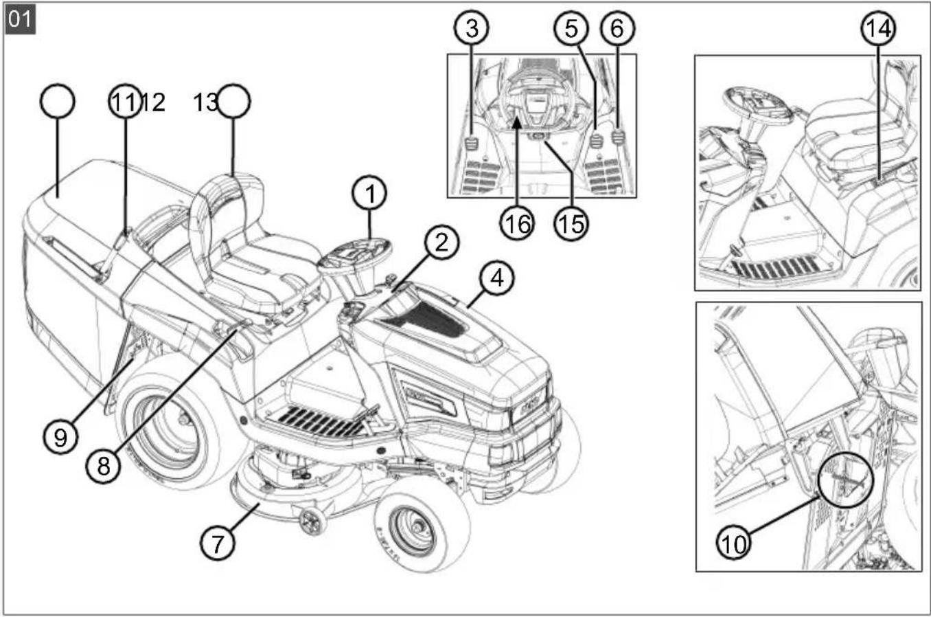
2.5 Product overview (01)
| No. Component |
| 1 Steering wheel |
| 2 Dashboard |
| 3 Brake pedal |
| 4 Engine cover |
| 5 Transmission activation reverse |
| 6 Transmission activation forwards |
| 7 Mower mechanism |
| 8 Cutting height adjustment |
| 9 Transmission bypass |
| 10 Grass catcher sensor |
| 11 Grass catcher operation |
| 12 Grass catcher |
| 13 Operator's seat |
| 14 Electric grass catcher operation* |
| 15 Locking lever for brake pedal |
| 16 Cruise control lever* |
* Configuration varies and depends on model
3 SAFETY INSTRUCTIONS
Children, or other people who are not familiar with the instructions for use, are not allowed to use the equipment.
■ Comply with local regulations on the minimum age of people operating the equipment.
- Do not allow children and young people to play on the machine.
■ Only mow during daylight hours or with good artificial lighting.
- Keep other people out of the danger area.
■ The user is responsible for accidents involving other people and their property.
■ Only use genuine spare parts and genuine accessories.
■ Repairs to the machine must be carried out by the manufacturer or by one of its customer service centres.
■ Wear hearing protection.
The lawn tractor does not have approval for road use and may not be driven on public roads.
■ Do not mow during thunderstorms. No protection against lightning strikes.
■ Do not carry any passengers on the machine.
■ Do not mow on slopes with more than 10^ (18 %) gradient
- Do not work with the lawn tractor and/or with accessories attached to it after you have consumed alcohol, medicines which impair reactions, or drugs.
■ Always mow across the slope.
■ Comply with the permitted operating times in your vicinity.
The lawn tractor can cause serious injuries due to its inherent weight. Take particular care when loading and unloading the lawn tractor before/after transport on a vehicle or trailer.
This lawn tractor is not allowed to be towed. Use a suitable vehicle for transport on public roads.
- Do not operate the lawn tractor in poorly ventilated working areas (e.g. a garage). The exhaust gases contain poisonous carbon monoxide as well as other harmful substances.
4 UNPACKING AND ASSEMBLING THE TRACTOR
Comply with the supplied assembly instructions for unpacking and assembling the tractor.
NOTE Also comply with the enclosed operating instructions for the petrol engine.
WARNING! Danger if assembly is not carried out completely! Do not operate the lawn tractor before it has been fully assembled! Carry out all the work described in the assembly instructions. If you are uncertain about anything, ask a specialist to confirm that the assembly has been carried out correctly before the machine is started up! Check whether all safety and protective devices are in place and functioning correctly!
5 CONTROLS
The following section describes the controls of lawn tractors with rear discharge. Make sure you are referring to the appropriate description for your lawn tractor.
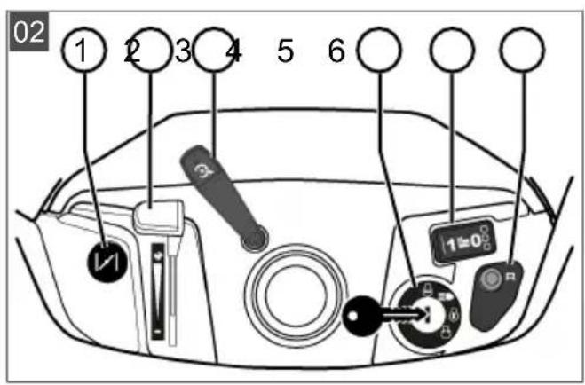
5.1 Standard dashboard (02)
The elements of the standard dashboard are explained below.
Controlling the engine speed
NOTE Please note that operating the controller while driving influences the speed!
For controller with integrated choke:
Moving the controller (02/2) increases or decreases the engine speed. The choke is activated in the highest position.

Switch on the choke: Push the controller all the way towards the choke symbol. Only use this position for starting the engine.
Note: Some tractor variants have a separate choke knob (02/1) on the dashboard. This must be pulled out as well in order to start the tractor. When the engine is running, slowly push the button back in!

Mowing: In this position, the engine runs at maximum speed.

Idling: In this position, the engine runs at the lowest speed.
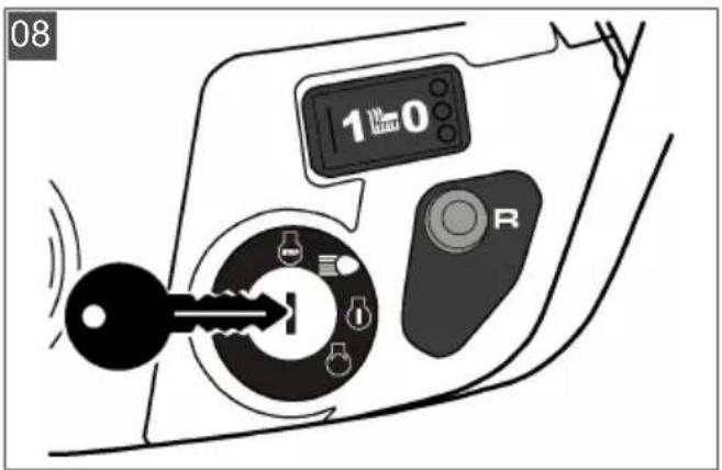
Ignition lock (02/4)
| Position Function | |
| 0 Engine off. | The ignition key can be removed. |
| I Headlights on. | The headlights are switched on in this position after the engine has started. |
| II Operating position when the engine is running. | |
| III Start position for starting the engine. | Release the key as soon as the engine is running. Then it springs back to operating position II. |
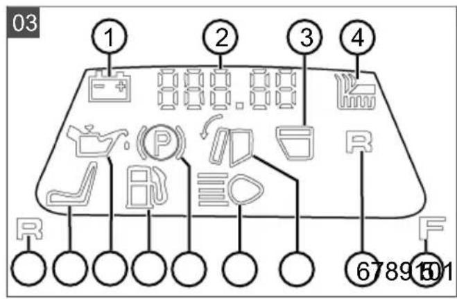
5.2 Dashboard with display (03)
Read this chapter if your lawn tractor has a display above the standard dashboard.
5.2.1 Function keys and display
| Item Designation Function | |
03/2 The display shows the following: | Daily operating hours (indicated to one decimal place)Note: The daily operating hours are indicated using the decimal system (1.5 h = 1 h 30 min).orTotal operating hours (indicated without decimal place)Note: The total operating hours start counting as soon as the ignition key is turned to position I. |
03/5 To change over the display: | Total operating hoursDaily operating hoursBattery voltageNote: Counting of the total operating hours continues if the ignition key is left in the ignition lock in position “I”. |
| 03/13 Resetting the daily operating hours to “0”.Note: Only the daily operating hours can be reset to “0”, not the total operating hours. | |
5.2.2 Pilot lights
| Item Designation The display lights up: | ||
| 03/1 |  | With the engine running:With the starter battery defective or flat.Discontinuity in the cable line from the engine to the bat-tery.Fuse blown (15 A blue).Alternator on engine defective.With the engine stopped:With the starter battery exhaustively discharged.Note: Contact the specialist workshop if this display lights up! |
03/3 If the grass catcher is full. | Empty the grass catcher! | |
03/4 If the mower mechanism is switched on. | ||
| 03/6 If operation of the mower mechanism is permitted in reverse. | ||
03/7 With the grass catcher removed or not correctly closed. | ||
| 03/8 | With the headlights switched on. | |
| 03/9 | If the brake is applied and with the brake locked. | |
| 03/10 | When there are only about 1.5 litres of fuel remaining in the tank. | |
| 03/11 | If the oil level is below a particular level. | |
| 03/12 | If the operator gets off the tractor with: | engine running (brake is locked) |
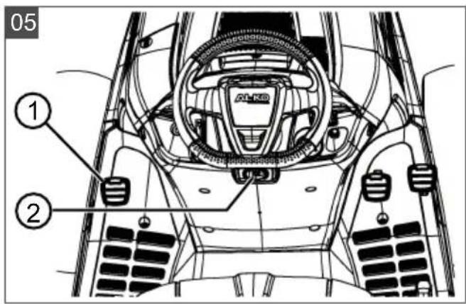
5.3 Brake and clutch pedal (05)
■ Brake: Pressing the brake pedal (05/1) all the way down operates the brake on the transmission and the tractor is braked.
Parking brake: Pulling the parking brake lever (05/2) upwards while the brake pedal (05/1) is pressed down engages the parking brake. Pressing the brake pedal again releases the parking brake.
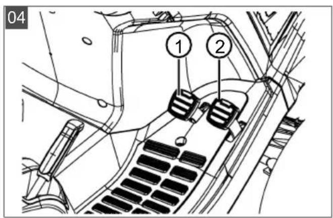
5.4 Transmission operation (driving speed) (04)
Lawn tractors are equipped with a foot hydrostat transmission.
Some models are equipped with cruise control. There are two separate pedals on the right for driving forwards and in reverse.
| Direction of travel | Description |
| Forwards | Press the right pedal (04/2) to drive forwards. |
| Reverse | Press the left pedal (04/1) to drive in reverse.Note: The mower mechanism is switched off if just the reverse pedal is pressed.Mowing in reverse: see chapter 7.5.5 "Mowing with the lawn tractor", page 39. |
5.5 Foot hydrostat transmission (04, 05)
The foot hydrostat transmission is operated by two pedals (04/1 and 04/2).
To move off, first release the parking brake (05/2) while the engine is running and then press pedal (04/2) to drive forwards or pedal (04/1) to reverse. The further you press the pedal, the faster your speed will be in the selected direction.
Forward travel: Press the outer pedal (04/2) on the right side.
Reverse travel: Press the inner pedal (04/1) on the right side.
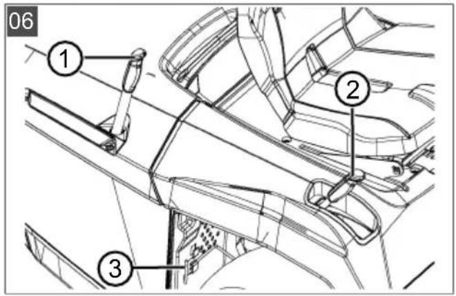
5.6 Operating the mower mechanism (06)
Setting the cutting height
The mower mechanism of the tractor can be set to various different heights using a lever (06/2) on the right next to the operator's seat.
- Move the adjusting lever (06/2) in the desired direction. When the lever is down, the cutting height is low; when the lever is up, the cutting height is high.
Switching on the mower mechanism
Switching on electrically: There is a switch (02/5) in the area of the dashboard. Use this to switch the mower mechanism on (i.e. to position "1").
6 START-UP
WARNING! Danger if assembly is not carried out completely! Do not operate the lawn tractor before it has been fully assembled! Carry out all the work described in the assembly in-
structions. If you are uncertain about anything, ask a specialist to confirm that the assembly has been carried out correctly before the machine is started up! Check whether all safety and protective devices are in place and functioning correctly!
6.1 Checking the mower mechanism
Before use, always look and check whether the cutter, fastening pin and the entire mowing unit are worn or damaged. Worn or damaged blades must be renewed by new ones in order to avoid any imbalance.
6.2 Oil fill
The engine must be filled with oil before initial start-up. Please comply with the instructions from the engine manufacturer in this regard. Also make sure the oil level is checked at regular intervals and the oil is topped up if necessary.
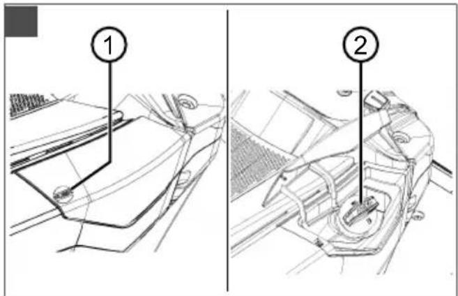
6.3 Filling with fuel (09)
WARNING! Dangers when handling fuel!
Fuel is highly inflammable. Only fill the fuel tank outdoors! Do not smoke! Do not refuel when the engine is running or is hot!
Use a suitable funnel or a filler pipe when refueling so that no fuel is spilled on the engine, the deck or the ground.
For safety reasons, the fuel tank cap and other tank caps must be renewed if damaged.
Do not start the engine if the fuel has overflowed.
The tractor must be removed from the area contaminated by fuel, and the spilled fuel must be absorbed and wiped away from the ground, the engine and the deck using a cloth.
Do not make any attempt to start the machine until fuel vapours have evaporated.
Only keep the fuel in containers intended for this purpose.
Use lead-free petrol, min. RON 91.
Filling the tank
- Switch off the engine if it is running and remove the ignition key as a precaution.
- Wait until the engine has cooled down somewhat (risk of explosion if the fuel catches fire!).
- Press on the tank cap cover (09/1).
-
Swivel the tank cap cover (09/1) upwards. The tank cap cover (09/1) is unlocked.
-
Open the tank cap (09/2) and pour in the fuel. Note: Avoid overfilling the fuel tank!
- Close the tank cap (09/2).
- Close the tank cap cover (09/1) so it engages.
6.4 Checking the tyre pressure
- Check the tyre pressure at regular intervals.
■ Please refer to the specification on the tyre for the necessary inflation pressure (recommendation: 1 bar).
NOTE 1 PSI = 0.07 bar.
The tyre pressure can be checked and the tyre inflated using a commercially available foot pump.
6.5 Fitting the grass catcher (10 - 13)
Lawn tractors are supplied with a grass catcher. Please note that the illustrations may differ somewhat from the original.
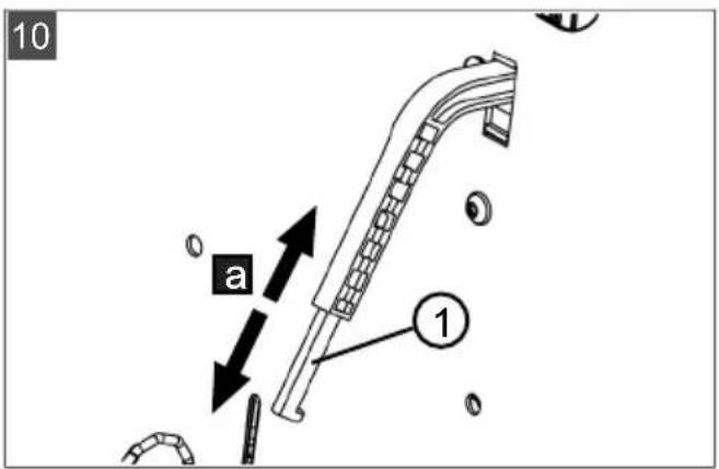
Adjusting the fill-level sensor of the grass catcher
The fill-level sensor uses a horn to signal when the grass catcher must be emptied.
The fill-level sensor can be set to 6 positions, depending on the condition of the cut grass. With dry grass, push the fill-level sensor to the smaller positions. With wet or damp grass, set the fill-level sensor to the higher positions. This influences the filling of the grass catcher.
- Shut off the engine (see chapter 7.4 "Starting and stopping the engine", page 38).
- Remove the grass catcher (see chapter 8.1 "Cleaning the grass catcher", page 41).
- Adjust the fill-level sensor (10/1) to suit the grass to be cut (10/a) until it engages in the desired position.
- Hook in the grass catcher again.
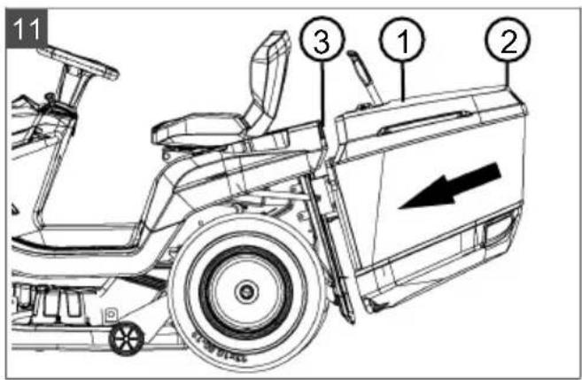
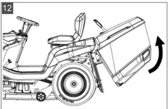
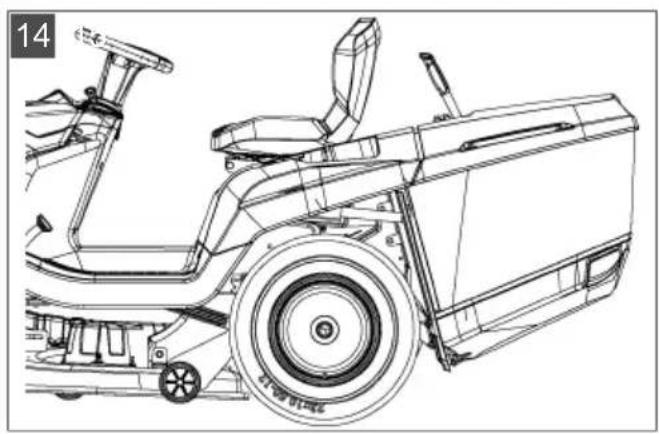
Hooking in the grass catcher
- Hold the grass catcher with one hand on the catcher handle (11/1) and the other hand on the holding opening at the back (11/2).
- Place the grass catcher symmetrically onto the guide (11/3).
- Use your other hand to tip the grass catcher slightly forward (12) so the front part of the grass catcher engages.
- Now swivel the grass catcher back down (13/a).
- Check the grass catcher is correctly seated.
6.6 Checking the safety devices
Check the safety devices each time before the lawn tractor is started.
WARNING! Danger when checking the safety devices! The safety devices are only allowed to be checked from the driver's seat, and when no other persons or animals are in the vicinity!
Carry out all checks on level ground so that the lawn tractor cannot roll away inadvertently.
6.6.1 Checking the brake contact switch
The brake contact switch ensures that the engine cannot be started if the brake is not applied.
- The engine is off.
- Sit on the operator's seat.
- Release the parking brake by pressing the brake pedal (05/1).
- Attempt to start the engine (ignition key in position III).
NOTE The engine is not allowed to start!
6.6.2 Checking the mower mechanism contact switch
The mower mechanism contact switch ensures that the engine cannot be started if the mower mechanism is activated.
- The engine is off.
- Sit on the operator's seat.
- Press the brake pedal (05/1) and the parking brake (05/2).
- Switch on the mower mechanism (02/5, position "1").
- Attempt to start the engine (ignition key in position III).
NOTE The engine is not allowed to start!
6.6.3 Checking the seat contact switch
The seat contact switch ensures that the engine switches off as soon as there is no-one on the operator's seat when the mower mechanism is switched on.
- Sit on the operator's seat.
- Press the brake pedal (05/1) and the parking brake (05/2).
- Start the engine and let it run at maximum rpm.
-
Switch on the mower mechanism (02/5, position "1").
-
Take your weight off the seat by standing up (do not get off!).
NOTE The engine must switch itself off!
6.6.4 Checking the grass catcher contact switch
The grass catcher contact switch ensures that the engine is switched off as soon as the grass catcher is no longer hooked in correctly when the mower mechanism is switched on.
- Sit on the operator's seat.
- Press the brake pedal (05/1) and the parking brake (05/2).
- Start the engine and let it run at maximum rpm.
- Switch on the mower mechanism (02/5, position "1").
- Lift the empty grass catcher slightly, or press the opening switch.
NOTE The engine must switch itself off!
6.6.5 Checking the discharge channel contact switch
The discharge channel contact switch ensures that the lawn tractor cannot be started when the discharge channel is removed.
- Remove the grass catcher.
- Remove the discharge channel (18/2).
- Sit on the operator's seat.
- Press the brake pedal (05/1) and the parking brake (05/2).
- Start the engine.
NOTE The engine is not allowed to start!
WARNING! Dangers due to inadequate knowledge of the lawn tractor! Read the operating instructions for use carefully before you start! Pay particular attention to all safety instructions! Carry out all assembly and start-up work conscientiously. Ask the manufacturer if you have any doubts!
7.1 Fundamental preparatory measures
■ Always wear tough shoes and long trousers while mowing. Never mow barefoot or when wearing open sandals.
- Check the complete area on which the lawn tractor is to be used. Remove all stones,
sticks, wires, bones and other foreign objects which could be scooped up and flung out. Also pay attention to foreign objects during mowing.
- Carry out all the work described in the start-up instructions. This applies in particular to checking the safety devices.
■ Only use the towing hitch for pulling loads! Do not exceed the imposed load limit.
■ Do not transport objects on the lawn tractor!
7.2 Use of accessories
WARNING! Danger due to incorrect accessories or incorrect use of accessories! Only ever use genuine accessories from the tractor manufacturer! Pay attention to the regulations on use in the supplied operating instructions!
Using unauthorised accessories, or using accessories incorrectly, can expose the operator and other persons to significant risks. The lawn tractor could be overloaded. This can lead to serious accidents.
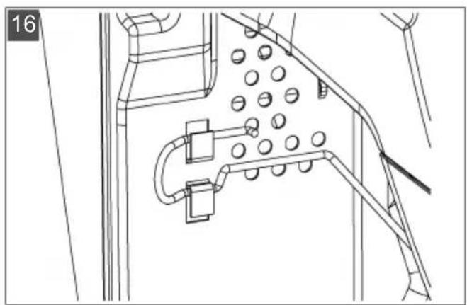
7.3 Pushing the lawn tractor (15, 16)
CAUTION! Danger when pushing on slopes! Only push the lawn tractor on level ground! On slopes, the lawn tractor could roll downhill uncontrollably.
For a foot hydrostatic drive
The bypass lever (15/1) is located in the rear right wheel housing.
Bypass unlocking on T3 transmission (type: T15, T16, T18):
- Pull out the bypass lever (15/1) and hook it in place upwards (16).
- Release the brake.
⇒ The lawn tractor can now be pushed.
Bypass unlocking on G700 transmission (type: T20, T23):
- Push in the bypass lever (15/1) and hook it in place upwards (16).
- Release the brake.
⇒ The lawn tractor can now be pushed.
7.4 Starting and stopping the engine
Starting the engine
- Sit on the operator's seat.
-
Press the brake pedal (05/1) on the left side down fully and lock it using the locking lever (05/2).
-
Make sure the mower mechanism is not switched on. To do this, check the position of the toggle switch (02/5, position "0").
- Move the engine speed controller (02/2) to the top end stop. The choke symbol is located there, depending on the equipment variant. If it is not, pull the separate choke knob (02/1).
- Insert the ignition key into the ignition lock (02/4).
- Turn the ignition key to position "III" and hold it there until the engine is running. Note: To reduce strain on the starter battery, do not attempt to start for any longer than about 5 seconds.
- Then release the ignition key, it automatically jumps to position "II".
- Move the engine speed controller (02/2) to the operating position. In an equipment variant with the choke knob, press it back in again (02/1).
- Switch off the mower mechanism (02/5).
- Move the controller (02/2) for the engine speed to the idling speed position.
- Press the brake pedal (05/1) and lock it using the locking lever (05/2).
- Turn the ignition key (02/4) to the "0" position.
- Remove the ignition key.
Switch off the engine
WARNING! Danger if the engine is hot!
When stopping the engine, ensure that hot engine components such as the silencer cannot set fire to objects or materials located nearby!
7.5 Driving with the tractor
WARNING! Danger in case of inappropriate speed! Drive slowly, especially at the beginning, in order to familiarise yourself with the driving and braking properties of the tractor! Before each change of direction, adjust the driving speed so as to retain control of the lawn tractor at all times, and to prevent it from tipping over!
Your tractor is driven via a foot hydrostat transmission.
7.5.1 Preparing to drive at temperatures below 10 °C
-
Make sure the mower mechanism is not switched on. To do this, check the position of the toggle switch (02/5, position "0").
-
Start the engine and let it run for about 30 seconds to warm up and optimise the gear oil viscosity. Following that, you can drive the tractor. Do not switch on the mower mechanism until the engine has been running for a few minutes.
7.5.2 Driving with the foot hydrostat transmission
- Press the brake pedal (05/1) and lock it using the locking lever (05/2).
- Set the mower mechanism to the maximum cutting height (06/2).
- Start the engine.
- Press the brake (05/1).
- Slowly press the foot pedal for the required driving direction:
■ Forwards: Foot pedal (04/2)
■ Reverse: Foot pedal (04/1)
- The further you press the pedal, the faster the tractor will drive in the selected direction.
- To stop, release the foot pedal and press the brake (05/1).
NOTE When you leave the tractor, always activate the locking lever when the brake pedal is pressed, to prevent the tractor from rolling away!
7.5.3 Driving with cruise control
NOTE The cruise control can only be switched on when driving forwards. Pressing the brake automatically switches the cruise control off.
Switching the cruise control on/off:
- Pivot lever (02/3) upwards. The cruise control is switched on.
- Pivot lever (02/3) downwards. The cruise control is switched off.
7.5.4 Driving and mowing on slopes
WARNING! Danger due to mistakes when driving on slopes! Be particularly careful when driving on slopes! There is no such thing as a "safe" slope. In particular, comply with the following safety instructions here! Disengage the mower mechanism and add-on devices if the wheels spin or the vehicle stalls when driving on a slope. Then drive away down the slope slowly, straight along the fall line! The weight of a full grass catcher increases the risk of the lawn tractor tipping over!
Do not drive on gradients of more than 10^ (18%). Example: This corresponds to a change of 18 cm in height over a distance of 1 metre.
Drive smoothly.
■ Do not brake suddenly.
- Keep the driving speed low.
■ Do not drive across the slope.
■ Do not accelerate suddenly.
■ Steer smoothly.
7.5.5 Mowing with the lawn tractor
Adapt the driving speed to the conditions of the lawn in order to achieve a tidy mowing result. Select at most two thirds of the possible driving speed at the pedal when mowing. The maximum speed of the tractor is exclusively intended for driving without the mower mechanism switched on.
Normally, the cutting height is 4 - 5 cm. This corresponds to the 2nd or 3rd detent of the height adjustment (06/2). Mow with a higher cutting height if the grass is moist or wet.
If the grass is very long, it is a good idea to mow in two passes. Set the mower mechanism to the maximum cutting height on the first pass. You can reduce it to the required height for the second pass.
7.5.5.1 Switching on the mower mechanism
NOTE Do not switch on the mower mechanism until the engine has been running for about one minute to warm up! The lawnmower should not be standing in tall grass when the mower mechanism is engaged.
- Start the engine.
- Move the engine speed controller (02/2) to the operating position.
- Set the mower mechanism to the maximum cutting height (06/2).
- Engage the mower mechanism using the toggle switch (02/5, position "1").
- Set the required cutting height using the hand lever (06/2).
- Set the lawn tractor in motion.
7.5.5.2 Mowing in reverse
NOTE The mower mechanism is switched off if just the reverse transmission pedal is pressed.
- Press the "Reverse mowing" button (02/6) and, within 5 seconds, press the pedal for reverse driving (04/1).
WARNING! There is an accident risk when reverse mowing! Pay attention to the area behind you when mowing in reverse! Only mow in reverse when it is necessary to do so!
7.5.5.3 Switching off the mower mechanism
WARNING! Danger due to spinning blades! When the cutting blades are still spinning, they can cause laceration injuries to hands and feet! As a result, keep your hands and feet away from the cutters!
- Disengage the mower mechanism using the toggle switch (02/5, position "0").
The mower mechanism can be switched off when the tractor is at a standstill and when it is being driven.
WARNING! Risk of injury due to objects being thrown out! When crossing areas of gravel and crushed stone, objects can be drawn into the running mower mechanism and then thrown out.
■ Always switch off the mower mechanism if you are driving over surfaces other than lawns.
7.5.5.4 Emptying the grass catcher
i NOTE An audible signal sounds when the grass catcher is full. The catcher should be emptied now if not before.
Depending on the equipment variant, your lawn tractor has electrically operated grass catcher emptying or a manually operated grass catcher with operating lever.
The following applies to all catcher types:
■ The grass catcher can be emptied from the operator's seat.
The engine cuts out if the grass catcher is lifted up or disconnected when the mower mechanism is switched on.
The mower mechanism cannot be switched on unless the grass catcher is engaged correctly.
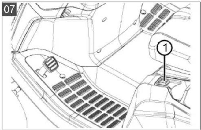
Emptying the electrically operated grass catcher
-
For emptying, operate the toggle switch (07/1) on the left of the operator's seat.
-
To close the grass catcher, operate the toggle switch again.
Emptying the grass catcher with operating lever
- Pull the operating lever out of the grass catcher (17/a).
- Push the lever in the driving direction so the grass catcher opens (17/b).
- Move the grass catcher backwards with the lever until the catcher engages.
7.5.5.5 Mulching
For optimum mulching results, the grass should be mowed on a regular basis (approx. 1 or 2 times per week). When doing so, cut 1/3 of the grass height (e.g. if grass height is 6 cm, mow 2 cm). This will ensure that the mown grass will be properly intermixed in the remaining grass.
7.5.5.6 Mowing interval
Please take into account that grass grows differently at different times. We recommend using a shorter interval between mowing during early spring. You can increase the mowing intervals as the growth rate of the grass begins to decline during the course of the year.
If you are unable to mow the grass for an extended period, you should initially select a higher cutting height setting, then re-mow two days later with a lower cutting height setting.
7.5.5.7 Mowing high grass
Mow with a higher cutting height adjustment when the grass is longer than normal or when it is wet. Then re-mow the grass with a lower, normal setting.
7.5.5.8 Cutting blade maintenance
Make sure that the cutting blade remains sharp for the entire mowing season to avoid shredding or tearing the blades of grass. Shredded grass blades turn brown on the edges. This reduces their growth and leaves the lawn prone to diseases.
- Check the cutting blade for sharpness and signs of wear or damage after each use! If necessary please contact a service workshop.
If replacement is required, only use original manufacturer replacement blades.
8 CLEANING THE LAWN TRACTOR
The lawn tractor must be cleaned regularly to ensure optimum function and a long service life.
Clean the lawn tractor after each use to remove adhering dirt and detritus.
Do not use a high-pressure cleaner for cleaning.
The water jet from a high-pressure cleaner or a garden hose can damage the electrical system or bearings.
In particular, make sure that no water comes into contact with the engine, transmission and deflection pulleys, as well as the entire electrical system.

WARNING! Dangers when cleaning!
During all cleaning work:
■ Switch off the engine and remove the ignition key.
■ Remove the spark plug connector.
■ Protective devices removed for cleaning must be reinstalled afterwards.
■ DANGER OF BURNS: Do not clean the lawn tractor until it has cooled down. The engine, transmission and silencer get very hot!
■ DANGER OF LACERATIONS: When working on the cutters, pay attention to the sharp blades. In mowers with more than one blade, moving one cutter can cause the other to move as well!
8.1 Cleaning the grass catcher
To do this, remove the grass catcher and clean it by spraying inside and out with a water hose.
Firmly adhering contamination must be scraped off carefully, such as by using a brush. Especially in grass catchers with a fabric covering, take care not to damage the fabric.

NOTE Empty the grass catcher before
cleaning as described. A full grass catcher is too heavy to be removed safely.
Removing a grass catcher
- Switch off the engine.
- Tilt the grass catcher slightly.
- Remove the grass catcher upwards.
Removing an electrically operated grass catcher
- Switch off the engine.
- Make sure that the electrically operated grass catcher is closed.
- Tilt the grass catcher (approx. 30^ ).
- Remove the grass catcher upwards.
8.2 Cleaning the deck, engine and transmission
IMPORTANT! Damage to the electrical system by penetrating water! Take care when cleaning the tractor with water to ensure that no water gets into the electrical system!
Do not use water or a high-pressure cleaner to spray down the engine or any of the bearing points (wheels, transmission, blade bearing).
Water penetrating the ignition system, carburettor and air filter can cause malfunctions. Water in the bearing points can lead to loss of lubrication, and thus cause irreparable damage to the bearings.
Use a cloth, hand brush, long-handled paintbrush or similar for removing dirt and grass residues.
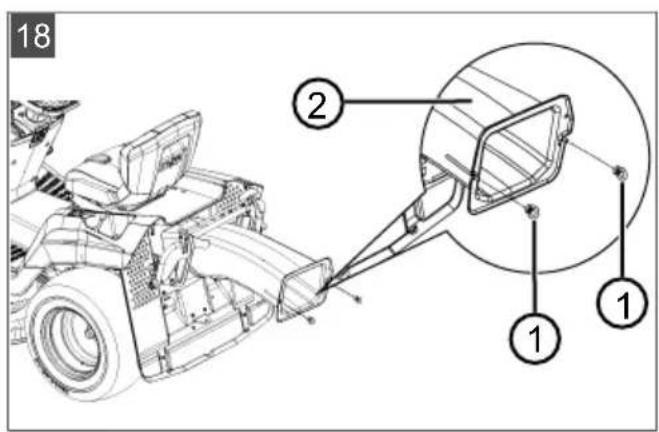
8.3 Cleaning the discharge channel (18)
Regular cleaning ensures that the cutting height adjustment can be moved easily.
The discharge channel consists of two parts pushed one inside the other. The lower part is firmly engaged in the lower deck. The upper part can be pulled out for cleaning.
- Remove the grass catcher.
- Remove the screws (18/1) on the left and right of the discharge channel (18/2).
- Pull the discharge channel through the back wall and out to the rear.
- Thoroughly clean the upper and lower discharge channel.
- Insert the discharge channel into the back wall. When doing this, make sure that the upper and lower parts fit cleanly one inside the other.
- Screw it on tight using the two fastening screws.
- Mount the grass catcher.
9 MAINTENANCE

WARNING! Dangers during maintenance!
During all maintenance work:
■ Switch off the engine and remove the ignition key.
■ Remove the spark plug connector.
■ Protective devices removed for maintenance must be reinstalled afterwards.
■ DANGER OF BURNS: Do not work on the lawn tractor until it has cooled down. The engine, transmission and silencer get very hot!
■ DANGER OF LACERATIONS: When working on the cutters, pay attention to the sharp blades. In case of mowers with multiple blades, moving one cutter can cause another one to move as well.
■ Parts are only allowed to be renewed by genuine spare parts.
If in doubt, always visit a specialist workshop or contact the manufacturer.
9.1 Maintenance schedule
The following jobs are allowed to be carried out by the user independently. All other maintenance, service and repair work must be carried out in an authorised service workshop.

NOTE It may be necessary to shorten the maintenance intervals compared to those stated in the table above in case of severe loading and at high temperatures.
In addition, please also comply with the recommended annual lubrication tasks as indicated in the lubrication plan.
| Activity Before | each use | After each use | After the first 5 hours | Every 25 operating hours | Every 50 operating hours | Each time before putting into storage |
| Check the engine oil level)* | X | |||||
| Change the engine oil)* | X | X | ||||
| Clean the air filter)* | X | |||||
| Replace the air filter)* | X | |||||
| Check the spark plug)* | X | |||||
| Check the brake (test braking on a straight path) | X | |||||
| Check the tyre pressure X | ||||||
| Check the mowing blades X | ||||||
| Check for loose parts X X | ||||||
| Check V-belts (visual check) X | ||||||
| Clean the lawn tractor X | ||||||
| Clean the air intake grille on the engine)* | X | |||||
| Clean the transmission to remove grass and mowing residues | X | X |
)* Refer to the operating instructions of the engine manufacturer
9.2 Lubricating plan
To ensure that moving parts can move freely, we recommend lubricating the following points at least once a year.
Use a cloth to clean all points to be lubricated before greasing or spraying. Do not use water, so as to avoid possible corrosion.
Lubrication points:
■ Grease the grease nipples on the right and left steering knuckles (21) using multi-purpose grease.
■ Spray oil onto the bearings of the front axle on the frame (21/1).
■ Grease the toothed segments and steering pinion on the steering box (22) using multi-purpose grease.
■ Grease the roller bearings and hub on the front and rear axles (23 / 20) with multi-purpose grease.
i NOTE The front and rear wheels must be removed for greasing the axles and bearings.
■ Pivoting and bearing points: Lubricate all movable pivoting and bearing points.
9.3 Wheel change
Wheel changes are only allowed to be carried out on firm, level ground.
- Park the lawn tractor and remove the ignition key.
- Press the brake pedal (05/1) fully and lock it using the locking lever (05/2).
- Secure the lawn tractor with chocks to prevent it from rolling away. Place the chocks under the side that is not being raised.
- Use suitable lifting gear (e.g. a scissor jack) to lift the lawn tractor on the side where the wheel should be changed. Lift the tractor until the wheel to be changed can turn freely.
Important! Danger of damage to the device!
Take care not to bend any tractor elements when lifting. Only position the jack on sturdy metal components. - Secure the lawn tractor by placing a sturdy support (e.g. a wooden block) under a supporting part of the chassis so that it cannot drop down even if the jack were to slip or tip over.
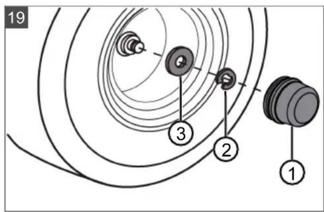
- Pull off the protective cap (19/1).
- Use a screwdriver to press out the lock washer (19/2). Make sure not to lose the parts.
- Pull off the plain washer (19/3).
-
Pull the wheel off the axle.
Note: Do not lose the feather key when pulling the rear wheels off the axle! -
Clean the axle and the hole in the wheel before reassembly, and grease both of them with multi-purpose grease.
-
Put the wheel onto the axle.
Note: When pushing on the rear wheels, make sure that the grooves for the feather key and the rear wheel are aligned so that the feather key can be pushed in without force.
-
Put the washer onto the axle.
-
Push the lock washer into the groove on the axle. If you use a pair of pliers to do this, take care not to damage the axle using the pliers.
-
Put the protective cap onto the axle.
-
Remove the securing support and use the jack to lower the tractor carefully down to the ground.
9.4 Starter battery
No charger is supplied for the starter battery of the lawn tractor.
Precise battery designation: see battery box. The starter battery is located under the engine cover.
The starter battery is always supplied from the factory pre-charged.
Safety instructions
WARNING! Danger if the starter battery is not handled correctly! The following points must be complied with to avoid the dangers arising from incorrect handling of the battery!
- Do not store the starter battery in the immediate vicinity of naked flames, do not burn it or place it on heaters. Risk of explosion.
■ Store the starter battery in a cool, dry room (10 - 15 °C) over the winter. Avoid storing at temperatures below the freezing point.
Do not leave the starter battery without charge for a long period. If the starter battery is not used for a long period, it should be charged using a suitable charger. - Do not smash the starter battery. The electrolyte (sulphuric acid) causes chemical burns to the skin and clothing – immediately rinse away with plenty of water.
- Keep the starter battery clean. Only wipe clean with a dry cloth. Do not use water, petrol, thinners or similar for this purpose.
- Keep the connection terminals clean and grease them with terminal grease.
■ Do not short-circuit the connection terminals.
Charging the starter battery
Charging is required:
Before putting into storage before the winter break.
If the machine will not be used for a long time (longer than 3 months).
WARNING! Danger if the starter battery
is not charged correctly! The charging current of the charger must not exceed 5 A, and the charging voltage can only be max. 14.4 V. Risk of explosion of the starter battery if the charging current is more powerful! Always remove the ignition key before starting work on the battery.
We recommend charging this maintenance-free, gas-tight starter battery using a specifically suitable charger (which can be obtained through retail outlets).
Comply with the operating instructions of the charger manufacturer before and during charging of the starter battery.
CAUTION! Danger of a short circuit! To
avoid a short circuit, always disconnect the negative cable (-) of the battery first, and reconnect it last! Always remove the ignition key before starting work on the battery!
- Remove the ignition key (02/4).
- Open the engine cover.
- Connect the charger terminals to the connection terminals of the battery.
NOTE Check the polarity:
■ Red terminal = positive terminal (+)
■ Black terminal = negative terminal (-)
- Connect the charger to the mains and switch it on.
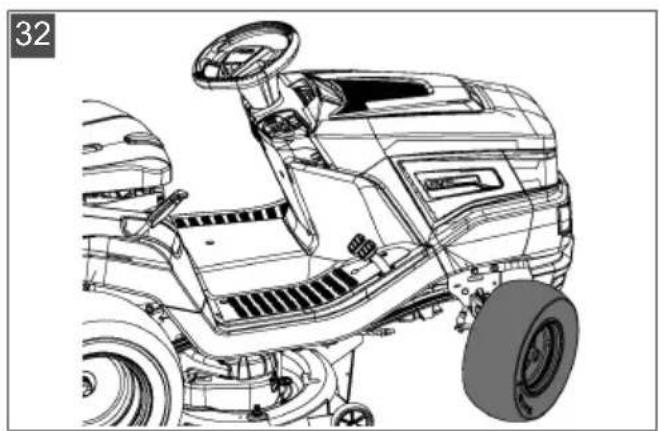
9.5 Removing the mower mechanism
The mower mechanism must be removed in order for the tractor to be used for snow clearing and for renewing the V-belt.
- Turn the steering wheel to full left lock (32).
- Remove the grass catcher (33).
- Remove the discharge channel (18).
- Unscrew the cap screw (34) on the channel holder by 5 - 6 turns.
- Lower the mower mechanism to the lowest setting (35).
-
Unhook the tension spring on the mower mechanism (36).
-
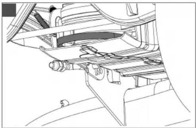
Move the mower mechanism back up to the top (37).
- Disconnect the V-belt duct (38).
- Unhook the V-belt from the V-belt sheave of the engine (39).
- Lower the mower mechanism back down to the lowest setting (40).
- Remove the 4 locking pins from the holding clips of the mower mechanism (41).
- Pull off the holding clips over the pins (41).
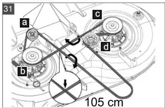
9.6 Renewing the V-belt
- Unscrew 6 locking nuts (24).
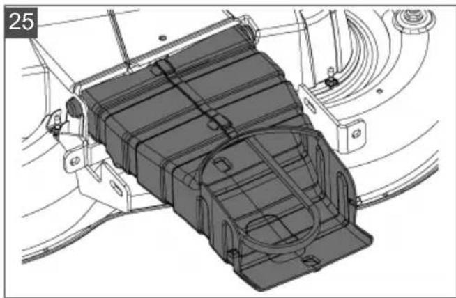
- Disconnect the V-belt duct (25).
- Unhook and remove the right cover of the mower mechanism (26).
- Unhook and remove the left cover of the mower mechanism (27).
- Unscrew the screw on the tensioning pulley slightly until the V-belt can be unthreaded (28).
- Remove the V-belt.
NOTE The guidance and orientation of the V-belt differs from type to type. Refer to the information stickers on the mower mechanism.
Inserting a new V-belt
- Place the V-belt around the slightly loosened tensioning pulley and screw the tensioning pulley on again (30 / 31).
- Place the V-belt around the rollers in the indicated sequence, making sure that the guidance and orientation of the V-belt are correct.
10 TRANSPORT
When the lawn tractor is transported using transport equipment (e.g. trailers towed by cars), the mower mechanism must be supported from below in order to reduce the strain on the mower mechanism mounting.
During transport, make sure that the means of transport has a sufficient load capacity and that the lawn tractor is suitably secured.
11 STORAGE
The lawn tractor should be parked where it is protected against the effects of weather, especially moisture, rain and lengthy exposure to direct sunlight.
Never store the lawn tractor inside a building when its fuel tank contains fuel, if there is potential for fuel vapours to come into contact with na-
ked flames or sparks. Only park the lawn tractor in rooms that are suitable for the storage of motor vehicles.
When storing the lawn tractor for long periods, such as over winter, it should not have its fuel tank filled if possible. The fuel can evaporate.
Before long-term storage, the fuel should be drained from the tank and the carburettor in order to avoid any build-up of deposits, which could result in problems when starting. Please contact your specialist workshop for advice.
12 HELP IN CASE OF MALFUNCTION
CAUTION! Risk of injury. Sharp-edged and moving appliance parts can lead to injury.
■ Always wear protective gloves during maintenance, care and cleaning work.
NOTE For malfunctions that are not listed in this table or that you cannot resolve yourself, please contact our customer service.
| Malfunction Cause Remedy | ||
| Engine does not start. Lack of fuel. Fill tank; check tank bleeding; check fuel filter. | ||
| Poor quality, contaminated fuel, old fuel in tank. | Always use fresh fuel from clean containers; clean carburettor (customer service workshop). | |
| Air filter contaminated. Clean air filter (see operating instructions from engine manufacturer). | ||
| No ignition spark. Clean the spark plug, replace with a new one if necessary, check ignition cable, check ignition system (customer service workshop). | ||
| Too much fuel in engine combustion chamber due to repeated starting attempts. | Unscrew spark plug and dry off. | |
| Starter does not work. | Starter battery flat or weakly charged. | Charge starter battery. |
| Safety switch on operator's seat does not function. | Sit on operator's seat correctly; switch defective. | |
| Safety switch on brake pedal does not function. | Press brake pedal down fully. | |
| Mower mechanism switched on. Switch off mower mechanism. | ||
| Fuse on (+) cable of starter battery. | Check fuse, replace if necessary. | |
| Motor is losing power. | Grass too long or too wet. Correct the cutting height; make clearance for mower mechanism by moving back a short distance. | |
| Discharge channel/mower deck blocked. | Stop engine and take out ignition key! Clean discharge channel/mower deck. | |
| Air filter contaminated. Clean air filter (see operating instructions from engine manufacturer). | ||
| Carburettor setting incorrect. Have the setting checked (customer service workshop). | ||
| Malfunction Cause Remedy | ||
| Blades severely worn down. Replace blades (customer service work-shop). | ||
| Driving speed too fast. Reduce driving speed. | ||
| Lawn tractor is vibrating severely. | Mower mechanism is damaged. Check mower mechanism (customer service workshop). | |
| Lawn tractor does not move off. | With hydrostat drive: no travel drive. | Move bypass lever to operating position (see chapter 7.3 "Pushing the lawn tractor (15, 16)", page 38). |
| Rough cut. Blade worn, | blunt. Renew or regrind blade. Reground blades must be rebalanced (customer service workshop)! | |
| Incorrect cutting height. Correct the cutting height. | ||
| Engine speed too slow. Set maximum engine speed. | ||
| Driving speed too fast. Reduce driving speed. | ||
| Different tyre pressure at wheels. Inflate to correct air pressure. Read off correct tyre pressure on tyre. | ||
| Grass catcher does not fill up. | Cutting height set too low. Correct the cutting height. | |
| Grass is wet – it is too heavy to be transported by air stream. | Mow at a later time when lawn has dried out. | |
| Blades severely worn down. Change blade. (Customer service work-shop) | ||
| Grass in lawn too tall. Mow grass twice:■ 1st pass: max. cutting height■ 2nd pass: desired cutting height. | ||
| Fabric bag blocked – no air throughput. | Clean fabric bag. | |
| Discharge channel/mower deck contaminated. | Clean discharge channel/mower deck. | |
| Fill level display does not respond. | Mown grass stuck to fill level display lever. | Remove mown grass from fill level display lever. Then check for ease of movement. |
| Travel drive, brake, clutch and mower mechanism. | Only have the check performed in a customer service workshop! | |
12.1 Fault and fault rectification error shown on display
| Display Fault Fault description Fault rectification | |||
| Err 01 | Seat switch ECU detects invalid status of the seat switch. | 1. Switch the ignition off and back on again (position 2)**2. Apply load and release load from seat several times■ Self-diagnosis, if necessary, automatic deletion of the fault*,■ otherwise contact Service | |
| Err 02 | Brake switch ECU detects invalid status of the brake switch. | 1. Switch the ignition off and back on again (position 2)**2. Press the brake pedal several times■ Self-diagnosis, if necessary, automatic deletion of the fault*,■ otherwise contact Service | |
| Err 03 | Mower mechanism switch | ECU detects invalid status of the mower mechanism switch. | 1. Switch the ignition off and back on again (position 2)**2. Press the mower mechanism switch several times■ Self-diagnosis, if necessary, automatic deletion of the fault*,■ otherwise contact Service |
| Err 04 | Box switch ECU detects invalid status of the box switch. | 1. Switch the ignition off and back on again (position 2)**2. Open and close the box several times■ Self-diagnosis, if necessary, automatic deletion of the fault*,■ otherwise contact Service | |
| Err 05 | Transmission switch | ECU detects invalid status of the transmission switch. | 1. Switch the ignition off and back on again (position 2)**2. Press the reverse pedal several times■ Self-diagnosis, if necessary, automatic deletion of the fault*,■ otherwise contact Service |
| Err 06 | Discharge channel contact switch | ECU detects invalid status of the discharge channel switch. | 1. Switch the ignition off and back on again (position 2)**2. Remove and re-install the discharge channel■ Self-diagnosis, if necessary, automatic deletion of the fault*,■ otherwise contact Service |
| Err 07 Mower mechanism contact switch | ECU detects incorrect status of the mower mechanism output. | 1. Switch the ignition off and back on again (position 1)■ Self-diagnosis, if necessary, automatic deletion of the fault*,■ otherwise contact Service | |
| Err 08 Start relay ECU detects incorrect status of the start relay output. | 1. Switch the ignition off and back on again (position 1)■ Self-diagnosis, if necessary, automatic deletion of the fault*,■ otherwise contact Service | ||
| Err 09 Solenoid valve ECU detects incorrect status of the engine solenoid valve output. | 1. Switch the ignition off and back on again (position 1)■ Self-diagnosis, if necessary, automatic deletion of the fault*,■ otherwise contact Service | ||
| Err 10 Ignition coil ECU detects incorrect status of the ignition coil output. | 1. Switch the ignition off and back on again (position 1)■ Self-diagnosis, if necessary, automatic deletion of the fault*,■ otherwise contact Service | ||
| Err 11 Internal supply voltage | ECU detects incorrect status of the internal supply voltage output. | 1. Switch the ignition off and back on again (position 1)■ Self-diagnosis, if necessary, automatic deletion of the fault*,■ otherwise contact Service | |
| Err 12 Internal supply voltage monitoring | ECU detects incorrect status of the internal supply voltage monitoring. | 1. Switch the ignition off and back on again (position 1)■ Self-diagnosis, if necessary, automatic deletion of the fault*,■ otherwise contact Service | |
| *: * The display goes out for about 4 seconds.**: Delete the error by pressing the R key (03/13). | |||
13 GUARANTEE
We will resolve any material or manufacturing faults on the appliance during the legal warranty period for claims relating to faults, in accordance with our choice either to repair or replace. The legal warranty period is determined by the legislation of the country in which the appliance was purchased.
Our warranty promise applies only if:
■ These operating instructions are heeded
The appliance is handled correctly
■ Original spare parts have been used
The warranty becomes void in the case of:
■ Unauthorised repair attempts
■ Unauthorised technical modifications
Non-intended use
The guarantee excludes:
■ Paint damage that can be attributed to normal wear and tear
■ Wear parts that are marked with a frame xxxxxx (x) on the spare parts card
■ Internal combustion engines (these are covered by the guarantee provisions of the corresponding engine manufacturers)
The guarantee period commences with purchase by the first end user. The date on the proof of purchase is decisive. In the event of a guarantee claim, please take this guarantee declaration and the original proof of purchase, and contact your dealer or the nearest authorised customer service centre. This statement does not affect the purchaser's statutory claims for defects against the vendor.
VERTALING VAN DE ORIGINELE GEBRUIKERSHANDLEIDING
Inhoudsopgave
2 PRODUCTOMSCHRIJVING
9.4 Akumulatorski zaganjalnik
■ Vip armen (02/3) ned.
Tempomat slås fra.
7.5.4 Kørsel og klipning på skråninger
10 Transport ....309
11 Förvaring 309
Koble inn klippeaggregatet
9.4 Akumulators....404


- Inhaltsverzeichnis
- ABOUT THESE INSTRUCTIONS FOR USE
- Symbols on the title page
- Symbol Meaning
- Legends and signal words
- PRODUCT DESCRIPTION
- Designated use
- Possible misuse
- Safety and protective devices
- SAFETY INSTRUCTIONS
- UNPACKING AND ASSEMBLING THE TRACTOR
- CONTROLS
- Standard dashboard (02)
- Controlling the engine speed
- Dashboard with display (03)
- Function keys and display
- Pilot lights
- Brake and clutch pedal (05)
- Transmission operation (driving speed) (04)
- Foot hydrostat transmission (04, 05)
- Operating the mower mechanism (06)
- Setting the cutting height
- Switching on the mower mechanism
- START-UP
- Checking the mower mechanism
- Oil fill
- Filling with fuel (09)
- WARNING! Dangers when handling fuel!
- Filling the tank
- Checking the tyre pressure
- NOTE 1 PSI = 0.07 bar.
- Fitting the grass catcher (10 - 13)
- Adjusting the fill-level sensor of the grass catcher
- Hooking in the grass catcher
- Checking the safety devices
- Checking the brake contact switch
- Checking the mower mechanism contact switch
- Checking the seat contact switch
- Checking the grass catcher contact switch
- Checking the discharge channel contact switch
- Fundamental preparatory measures
- Use of accessories
- Pushing the lawn tractor (15, 16)
- For a foot hydrostatic drive
- Starting and stopping the engine
- Starting the engine
- Switch off the engine
- WARNING! Danger if the engine is hot!
- Driving with the tractor
- Preparing to drive at temperatures below 10 °C
- Driving with the foot hydrostat transmission
- Driving with cruise control
- Driving and mowing on slopes
- Mowing with the lawn tractor
- Switching on the mower mechanism
- Mowing in reverse
- Switching off the mower mechanism
- Emptying the grass catcher
- Emptying the electrically operated grass catcher
- Emptying the grass catcher with operating lever
- Mulching
- Mowing interval
- Mowing high grass
- Cutting blade maintenance
- CLEANING THE LAWN TRACTOR
- WARNING! Dangers when cleaning!
- Cleaning the grass catcher
- Removing a grass catcher
- Removing an electrically operated grass catcher
- Cleaning the deck, engine and transmission
- Cleaning the discharge channel (18)
- MAINTENANCE
- WARNING! Dangers during maintenance!
- Maintenance schedule
- Lubricating plan
- Wheel change
- Starter battery
- Safety instructions
- Charging the starter battery
- WARNING! Danger if the starter battery
- CAUTION! Danger of a short circuit! To
- NOTE Check the polarity:
- Removing the mower mechanism
- Renewing the V-belt
- Inserting a new V-belt
- TRANSPORT
- STORAGE
- HELP IN CASE OF MALFUNCTION
- GUARANTEE
- VERTALING VAN DE ORIGINELE GEBRUIKERSHANDLEIDING
- Inhoudsopgave
- PRODUCTOMSCHRIJVING
- Akumulatorski zaganjalnik
- Kørsel og klipning på skråninger
- Koble inn klippeaggregatet
Brand : AL-KO
Model : Solo T 20105.6 HD V2 Premium
Category : Tractor