TDC1412 - Humidifier Toyotomi - Free user manual and instructions
Find the device manual for free TDC1412 Toyotomi in PDF.

| Product Type | Dehumidifier |
| Brand | Toyotomi |
| Model | TDC1412 |
| Dehumidification Capacity | 12 L/day (at 30 °C, 80% RH) |
| Power Supply | 220-240 V ~ 50 Hz |
| Power Consumption | 210 W |
| Refrigerant | R290 (50 g) |
| Net Weight | 10.5 kg |
| Operating Range | 7 °C to 35 °C |
| Adjustable Humidistat | Yes, from 40% to 80% in 5% increments |
| Timer | 1 to 24 hours (auto on/off) |
| Child Lock | Yes |
| Silent Mode | Yes |
| Auto Defrost | Yes |
| Air Filter | Washable; optional activated carbon filter (annual replacement recommended) |
| Water Tank | Removable with full tank indicator; continuous drainage possible |
| Operating Pressure (high/low) | 1.8 / 0.6 MPa |
| Maximum Pressure | 3.00 MPa |
| Protection Rating | IPX1 |
| Warranty | 24 months |
Frequently Asked Questions - TDC1412 Toyotomi
User questions about TDC1412 Toyotomi
0 question about this device. Answer the ones you know or ask your own.
Ask a new question about this device
Download the instructions for your Humidifier in PDF format for free! Find your manual TDC1412 - Toyotomi and take your electronic device back in hand. On this page are published all the documents necessary for the use of your device. TDC1412 by Toyotomi.
USER MANUAL TDC1412 Toyotomi
natural_image
Line drawing of a portable air purifier with wheels and control panel (no text or symbols)TD-C1410
TD-C1412
DEHUMIDIFIER
DÉSHUMIDIFICATEUR D'AIR
LUFTENTFEUCHTER
LUCHTONTVOCHTIGER
DEUMIDIFICATORE
DESHUMIDIFICADOR
DESUMIDIFICADOR
AFFUGTER
LUFTAVFUKTARE
OSUSZACZ
OPERATING MANUAL ENGLISH P. 1
MANUAL D'UTILISATION FRANÇAIS P. 9
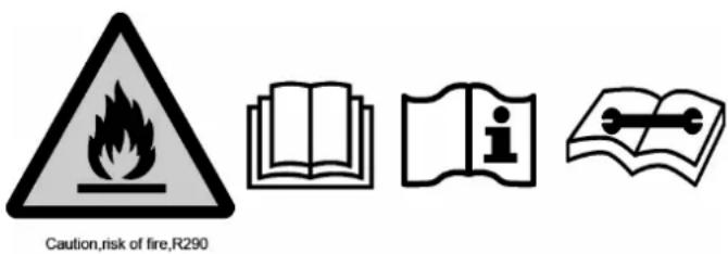
Appliance filled with flammable gas R290.

Before use the appliance, read the owner's manual first.

Before install the appliance, read the installation manual first.

Before repair the appliance, read the service manual first.
NOTICE
- Read this user manual carefully before using the appliance and keep it for future reference.
- Install this device only when it complies with local/national legislation, ordinances and standards.
- This product is intended to be used as a dehumidifier in residential houses and is only suitable for use in dry locations, in normal household conditions, indoors in living room, kitchen and garage.
- DO NOT place the dehumidifier in bathrooms or in other places where it is likely that water could be sprayed on.
- Always plug this product in a single phase electrical socket 220-240 V /\~50 Hz.
- Failing to follow the instructions may lead to nullification of the guarantee on this device.
- Follow strictly the manufacturer's instruction concerning use and repairs!
SAFETY WARNINGS
When using the unit, please observe the following safety precautions:
- Unplug the power supply cord before cleaning or storage.
- The appliances can be used indoor but not in laundry rooms.
- DO NOT set the unit close to heat-generating devices or near flammable and dangerous materials.
- NEVER put your fingers or objects into the intake or discharge ducts.
- DO NOT sit or stand on the unit.
- Discard water that has collected in the tank as required.
- DO NOT operate the dehumidifier in a closed area such as inside a closet, as it may cause a fire.
- DO NOT sue the unit near edible items, objects of art, or scientific materials.
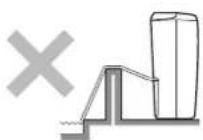
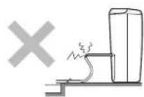
- Install drain piping at a downhill grade to make sure that condensed water can be drained continuously.
- If the power supply cord is damaged it must be replaced by the manufacture or a similarly qualified person in order to avoid a hazard.
- The appliance must be positioned so that the plug is accessible.
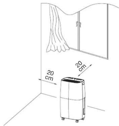
- Please keep a distance 20 cm around unit and the wall or other objects to ensure air circulation.
- The appliance shall be installed in accordance with local national wire regulations.
- The appliance cannot be used in public transportation.
- This appliance can be used by children aged from 8 years and above and persons with reduced physical, sensory or mental capabilities or lack of experience and knowledge if they have been given supervision or instruction concerning use of the appliance in a safe way and understand the hazards in-
volved. Children shall not play with the appliance. Cleaning and user maintenance shall not be made by children without supervision.
- Children should be supervised to ensure that they do not play with the appliance.
- Appliances that are obviously damaged must not be operated.
WARNING
Specific information regarding appliances with R 290 refrigerant gas:
- Appliance is filled with flammable gas R290.
- R290 is a refrigerant gas that complies with the European directives on the environment. It is a natural refrigerant (propane), non-toxic and free of ozone-depleting properties, with a very low global warming potential (GWP = 3).
- DO NOT pierce any part of the refrigerant circuit.
- DO NOT use means to accelerate the defrosting process or to clean, other than those recommended by the manufacturer.
- The appliance shall be stored in a room without continuously operating ignition sources (for example: open flames, an operating gas appliance or an operating electric heater).
- DO NOT pierce or burn.
- Be aware that refrigerants may not contain an odour.
- Appliance shall be installed, operated and stored in a room with a floor area larger than 4 m ^2 .
- If the appliance is installed, operated or stored in a non-ventilated area, the room must be designed to prevent to the accumulation of refrigerant leaks resulting in a risk of fire or explosion due to ignition of the refrigerant caused by electric heaters, stoves, or other sources of ignition.
-
The appliance shall be compliance with national gas regulations.
-
Servicing shall be performed only as recommended by the manufacturer.
- The appliance shall be stored so as to prevent mechanical damage from occurring.
- Any person who is involved with working on or breaking into a refrigerant circuit should hold a current valid certificate from an industry-accredited assessment authority, which authorises their competence to handle refrigerants safely in accordance with an industry recognised assessment specification.
- Servicing shall only be performed as recommended by the equipment manufacturer. Maintenance and repair requiring the assistance of other skilled personnel shall be carried out under the supervision of the person competent in the use of flammable refrigerants.
- Any repairs you need, contact the nearest authorized Service Center and strictly follow manufacturer's instruction only.
WARNING FOR DISPOSAL
It is prohibited to dispose of this appliance in domestic household waste. For disposal there are several possibilities.
1 DO NOT dispose this product as unsorted municipal waste. Collection of such waste separately for special treatment is necessary.
2 The municipality has established collection systems, where electronic waste can be disposed of at least free of charge to the user.
3 The manufacturer will take back the old appliance for disposal at least free of charge to the user.
4 As old products contain valuable resources. They can be sold to scrap metal dealers.
Wild disposal of waste in forests and land scapes end angers your health when hazardous substances leak into the groundwater and find their way into the food chain.
Meaning of crossed out wheeled dustbin. DO NOT dispose of electrical appliances as unsorted municipal waste, use separate collection facilities. Contact you local government for information regarding the collection systems available. If electrical appliances are disposed of in landfills of dumps. Hazardous substances can leak into the groundwater and get into the foodchain, damaging your health and well-being.
This marking indicates that this product should not be disposed with other household wastes throughout the EU. To prevent possible harm to the environment or human health from uncontrolled waste disposal, recycle it responsibly to promote the sustainable reuse of material resources. To return your used device, please use the return and collection systems or contact the retailer where the product was purchased. They can take this product for environmental safe recycling. R290: 3
GENERAL
To obtain optimum performance from your dehumidifier, ensure that all windows are closed in order to achieve maximum efficiency.
The capacity of the dehumidifier depends on the temperature and the humidity in the room, at lower temperatures less moisture will be removed.
FEATURES
Powerful Dehumidifying Capability
Taking advantage of refrigeration technology, the dehumidifier powerfully removes moisture from the air to decrease the humidity level of the room and keep the indoor air dry and comfortable.
Lightweight Portable Design
The dehumidifier is built to be compact and lightweight. The casters on the bottom of the unit make it easy to move from room to room.
Low Temperature Operation with Automatic Defrost
When the unit is running in a room temp. between 7^ C and 12^ C, it will be stop to defrost for every 30 minutes.
When the unit is running in a room temp between 12^ C and 20^ C, it will be stop to defrost for every 45 minutes.
Adjustable Humidistat
Adjust the desired humidity level by the humidistat.
Timer On / Off
Program the unit to turn on and off automatically.
Quiet Operation
The dehumidifier operates with a low noise level.
Energy Efficient
The power consumption of the unit is low.
1. DESCRIPTION
PARTS
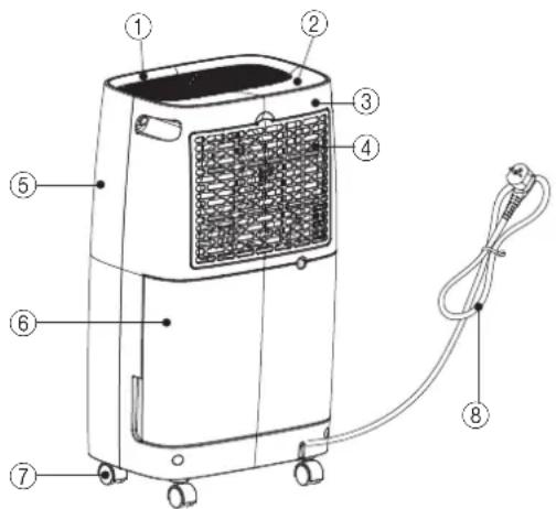
- Top panel 2. Control Panel 3. Back shell
- Filter box 5. Front shell 6. Water tank
- Caster 8. Supply cord
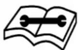
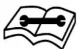
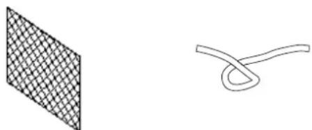
OPTIONAL
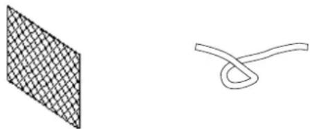
natural_image
Two abstract geometric shapes: a grid-patterned square and a curved line with loop (no text or symbols)- Activated carbon filter 2. Drainage hose
OPERATION PANEL
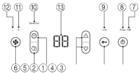
- Power button
- Adjustment button
- Setting button
- Water full lamp
- Childproof lock lamp
- High-fan lamp
-
Indication panel
-
Childproof lock button
-
Timer button
-
Fan speed button
-
Power lamp
-
Timer/Set lamp
-
Low-fan lamp
2. OPERATION
Humidity Level & Timer 2 digit display
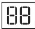
The indicator features 3 functions:
- When the unit is turned on, it will indicate the room humidity level.
- When you set the humidity, it will indicate the humidity that you have selected.
- When you program the time for the unit to turn on and off, it will show the hours.
- When the environment humidity is lower than 35%, it will show "35".
- When the environment humidity is higher than 95%, it will show "95".
3. OPERATING INSTRUCTIONS
- The Power indication light will turn on when the unit is plugged in, regardless of whether the unit is operating or not.
- Press button once to start operation. Press it again to stop operation.
- Press 📄 button as follows:
Press to set the desired fan speed. It can be adjusted between high speed and low speed.
- Press Ⓞ button to set the desired humidity level in the room, which can be set from 40% to 80% at 5% intervals.
After a period of working, when environment humidity is lower than the selected humidity by 2%, compressor will stop and fan continues to run without dehumidification function; When environment humidity is equal to or higher than the selected humidity by 2%, compressor will restart.
- Press Ⓞ button and then △ or ▽ to set the timer setting: You can only set the auto-shut off timer while the unit is operating (on). You can only set the auto-start timer while the unit is in standby (off). When the unit is on, press the Ⓞ button and adjust △ or ▽ to setup the power-off time. When the unit is standby, press the Ⓞ button and adjust △ or ▽ to setup the power-on time. Press Ⓞ button and then press the △ or ▽ button to set timer from 01-02.....23-24 hour. Press Ⓞ button and then △ or ▽ button to adjust the time to 00 to cancel timer. The programmed time remains unchanged if the machine stops to work due to water full or during defrosting. Once turned on or off by user, the timer function will be canceled.
- Press button to activate CHILD LOCK. You can activate the CHILD LOCK function by pressing the button for more than 5 seconds. The lamp will light up. When the CHILD LOCK function is activated, all buttons are locked. To cancel, press the button for more than 5 seconds until the lamp turns off.
4. DRAINING THE COLLECTED WATER
When the drainage tank is full, the tank full indicator light will turn on, the operation will stop automatically and the buzzer will beep 15 times to alert the user, that the water need to be emptied from the drainage tank.
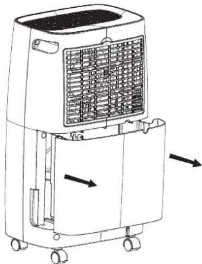
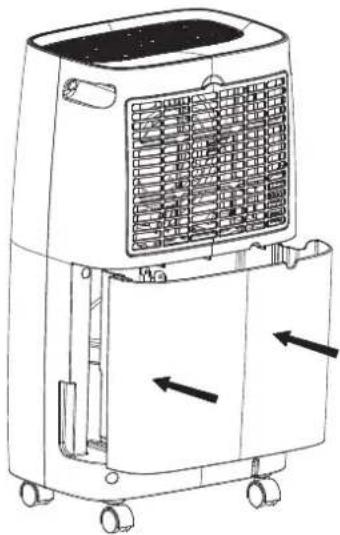
5. EMPTYING THE DRAINAGE TANK
- Lightly press on the sides of the tank with both hands and pull the tank out gently.
natural_image
Line drawing of a portable air conditioner unit with cooling fins and wheels (no text or symbols)- Discard the collected water.
natural_image
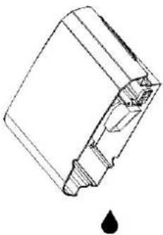
Technical line drawing of a mechanical component with a droplet symbol below (no text or labels)NOTE
- Do not remove the float from the water tank. The water full sensor will no longer be able to detect the water level correctly without the float and water may leak from the water tank.
natural_image
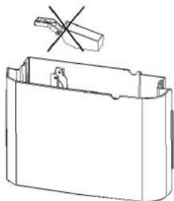
Technical line drawing of a battery pack with a cross symbol indicating a disassembled component (no text or labels present)- If the drainage tank is dirty, wash it with cold or lukewarm water. Do not use detergent, scouring pads, chemically treated dust cloths, gasoline, benzene, thinner, or other solvents, as these can scratch and damage the tank and cause water leakage.
- When replacing the drainage tank, press the tank firmly into place with both hands. If the tank is not positioned properly, the "TANK FULL" sensor will be activated, and the dehumidifier will not operate.
natural_image
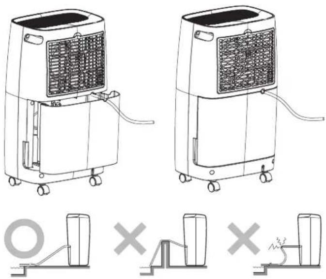
Line drawing of a portable air conditioner unit with cooling fins and wheels (no text or symbols)6. CONTINUOUS WATER DRAINAGE
The unit features a continuous drainage port. Using a plastic pipe (with an inner diameter of 10 mm) inserts into drain hole (on intermediate plate), reach out from side of water tank, install it in place, and arrange the drain pipe.
The water in the drainage tank can be continuously drained out from the continuous port on the unit.
7. MAINTENANCE
Cleaning the Dehumidifier
To Clean the Body
Wipe it with a soft damp cloth.
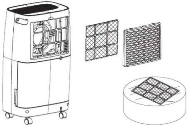
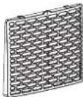
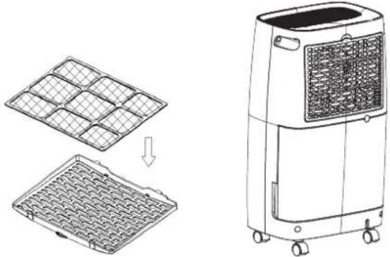
To Clean the Air Filter
- Open the inlet grill firstly and remove the air filter.
natural_image
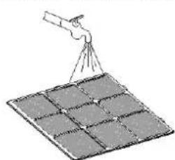
Technical line drawings of a portable air conditioner unit with internal components and a grid-patterned panel (no text or symbols)2. Clean the air filter
Run a vacuum cleaner lightly over the surface of the air filter to remove dirt. If the air filter is exceptionally dirty, wash it with warm water and a mild cleanser and dry thoroughly.
natural_image
Illustration of a person using a tool to spray or spray over a grid-patterned surface (no text or symbols)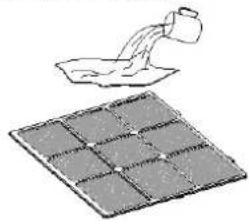
natural_image
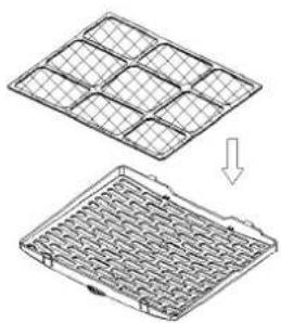
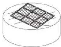
Illustration of a container being poured into a tray with a handle, showing liquid level (no text or symbols)3. Attach the air filter
Insert the filter into the grill smoothly, and place the inlet grill into right place.
natural_image
Two technical diagrams showing a grid-patterned panel being cut with an arrow indicating downward motion (no text or symbols present)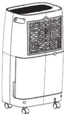
natural_image
Line drawing of a portable air conditioner unit with control panel and wheels (no text or symbols)- The activated carbon filter should not be washed / immersed into water. Use only vacuum cleaner in order to clean activated carbon filter.
IMPORTANT: The activated carbon filter fitted inside the filter frame by lifting the existing air filter. Changing of Active Carbon filter is recommended every one year (depending on the use of the product).
Storing the Dehumidifier
When the unit is not being used for a long period of time and you want to store it note the following steps:
- Empty any water left in the drainage tank.
- Fold up the power supply cord and put it in the water tank.
- Clean the air filter.
- Discard in a cool and dry place.
natural_image
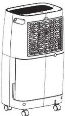
Line drawing of a portable air purifier with control panel and wheels (no text or symbols)Clearance
Maintain the minimum clearance around the dehumidifier when the unit is operating as shown in the left drawing.
8. TROUBLESHOOTING
If a condition listed below occurs, please check the following items before calling customer service.
| Problem Possible Cause Solution | ||
| The unit does not operate | Has the power cord been disconnected? | Plug the power cord into the outlet. |
| Is the tank full indication lamp blinking? (The tank is full or in a wrong position.) | Empty the water in the drainage tank and then reposition the tank. | |
| Is the temperature of the room above 35°C or below 7°C? | The protection device is activated and the unit cannot be started. | |
| The dehumidifying function does not work | Is the air filter clogged? | Clean the air filter as instructed under “Cleaning the dehumidifier”. |
| Is the intake duct or discharge duct obstructed? | Remove the obstruction from the discharge duct or intake duct. | |
| No air is discharged | Is the air filter clogged? | Clean the air filter as instructed under “Cleaning the dehumidifier”. |
| Operation is noisy | Is the unit tilted or unsteady? | Move the unit to a stable, sturdy location. |
| Is the air filter clogged? | Clean the air filter as instructed under “Cleaning the dehumidifier”. | |
9. NOTE FOR MAINTENANCE WORK
1. Checks to the area
Prior to beginning work on systems containing flammable refrigerants, safety checks are necessary to ensure that the risk of ignition is minimised. For repair to the refrigerating system, the following precautions shall be complied with prior to conducting work on the system.
Work procedure
Work shall be undertaken under a controlled procedure so as to minimise the risk of a flammable gas or vapour being present while the work is being performed.
2. General work area
All maintenance staff and others working in the local area shall be instructed on the nature of work being carried out. Work in confined spaces shall be avoided. The area around the workspace shall be sectioned off. Ensure that the conditions within the area have been made safe by control of flammable material.
3. Checking for presence of refrigerant
The area shall be checked with an appropriate refrigerant detector prior to and during work, to ensure the technician is aware of potentially flammable atmospheres. Ensure that the leak detection equipment being used is suitable for use with flammable refrigerant, i.e. nonsparking, adequately sealed or intrinsically safe.
4. Presence of fire extinguisher
If any hot work is to be conducted on the refrigeration equipment or any associated parts, appropriate fire extinguishing equipment shall be available to hand. Have a dry powder or CO2 fire extinguisher adjacent to the charging area.
5. No ignition sources
No person carrying out work in relation to a refrigerant system which involves exposing any pipe work that contains or has contained flammable refrigerant shall use any sources of ignition in such a manner that it may lead to the risk of fire or explosion. All possible ignition sources, including cigarette smoking, should be kept sufficiently far away from the site of installation, repairing, removing and disposal, during which flammable refrigerant can possibly be released to the surrounding space. Prior to work taking place, the area around the equipment is to be surveyed to make sure that there are no flammable hazards or ignition risks. "No Smoking" signs shall be displayed.
6. Ventilated area
Ensure that the area is in the open or that it is adequately ventilated before breaking into the system or conducting any hot wok. A degree of ventilation shall continue during the period that the work is carried out. The ventilation should safely disperse any released refrigerant and preferably expel it externally into the atmosphere.
7. Checks to the refrigeration equipment
Where electrical components are being changed, they shall be fit for the purpose and to the correct specification. At all times the manufacturer's maintenance and service guidelines shall be followed. If in doubt consult the manufacturer's technical department for assistance.
The following checks shall be applied to installations using flammable refrigerants:
- the charge size in accordance with the room size within which the refrigerant containing parts are installed;
- the ventilation machinery and outlets are operating adequately and are not obstructed.
8. Checks to electrical devices
Repair and maintenance to electrical components shall include
initial safety checks and components inspection procedures. If a fault exists that could compromise safety, then no electrical supply shall be connected to the circuit until it is satisfactorily dealt with. If the fault cannot be corrected immediately but it is necessary to continue operation, an adequate temporary solution shall be used. This shall be reported to the owner of the equipment so all parties are advised.
Initial safety checks shall include:
- that capacitors are discharged: this shall be done in a safe manner to avoid possibility of sparking;
- that there no live electrical components and wiring are exposed while charging, recovering or purging the system;
- that there is continuity of earth bonding.
9. Repairs to sealed components
During repairs to sealed components, all electrical supplies shall be disconnected from the equipment being worked upon prior to any removal of sealed covers, etc.
If it is absolutely necessary to have an electrical supply to equipment during servicing, then a permanently operating form of leak detection shall be located at the most critical point to warn of a potentially hazardous situation.
Particular attention shall be paid to the following to ensure that by working on electrical components, the casing is not altered in such a way that the level of protection is affected. This shall include damage to cables, excessive number of connections, terminals not made to original specification, damage to seals, incorrect fitting of glands, etc.
Ensure that apparatus is mounted securely.
Ensure that seals or sealing materials have not degraded such that they no longer serve the purpose of preventing the ingress of flammable atmospheres, Replacement parts shall be in accordance with the manufacturer's specifications.
NOTE: The use of silicon sealant may inhibit the effectiveness of some types of leak detection equipment. Intrinsically safe components do not have to be isolated prior to working on them.
10. Repair to intrinsically safe components
Do not apply any permanent inductive or capacitance loads to the circuit without ensuring that this will not exceed the permissible voltage and current permitted for the equipment in use. Intrinsically components are the only types that can be worked on while live in the presence of a flammable atmosphere. The test apparatus shall be at the correct rating.
Replace components only with parts specified by manufacturer. Other parts may result in the ignition of refrigerant in the atmosphere from a leak.
11. Cabling
Check that cabling will not be subject to wear, corrosion, excessive pressure, vibration, sharp edges or any other adverse environmental effects. The check shall also take into account the effects of aging or continual vibration from sources such as compressors or fans.
12. Leakage detection for flammable refrigerants
Under no circumstances shall potential sources of ignition be used in the searching for or detection of refrigerant leaks. A halide torch (or any other detector using a naked flame) shall not be used.
13. Leak detection methods
The following leak detection methods are acceptable for systems containing flammable refrigerant.
Electronic leak detectors shall be used to detect flammable refrigerants, but the sensitivity may not be adequate, or may need recalibration (Detection equipment shall be calibrated in a refrigerant-free area). Ensure that detector is not a potential source of ignition and is suitable for the refrigerant used.
Leak detection fluids are suitable for use with most refrigerants but the use of detergents containing chlorine shall be avoided as the chlorine may react with the refrigerant and corrode the copper pipe-work.
If a leak is suspected, all naked flames shall be removed/extinguished.
If a leak of refrigerant is found which requires brazing, all of the refrigerant shall be recovered from the system. Oxygen free nitrogen (OFN) shall then be purged through the system both before and during the brazing process.
14. Removal and evacuation
When breaking into the refrigerant circuit to make repairs-or for any other purpose-conventional procedures shall be used. However, it is important that best practice is followed since Flammability is a consideration. The following procedure shall be adhered to:
Remove refrigerant;
Purge the circuit with inert gas;
Evacuate:
Purge again with inert gas;
Open the circuit by cutting or brazing.
The refrigerant charge shall be recovered into the correct recovery cylinders. The system shall be "flushed" with OFN to render the unit safe. This process may need to be repeated several times. Compressed air or oxygen shall not be used for this task.
Flushing shall be achieved by breaking the vacuum in the system with OFN and continuing to fill until the working pressure is achieved, then venting to atmosphere, and finally pulling down to a vacuum. This process shall be repeated until no refrigerant is within the system. When the final OFN charge is used, the system shall be vented down to atmospheric pressure to enable work to take place.
This operation is absolutely vital if brazing operations on the pipe-work are to take place. Ensure that the outlet for the vacuum pump is not close to any ignition sources and there is ventilation available.
15. Refrigerant Charging procedures
In addition to conventional charging procedures, the following requirements shall be followed.
- Ensure that contamination of different refrigerants does not occur when using charging equipment. Hoses or lines shall be as short as possible to minimise the amount of refrigerant contained in them.
- Cylinders shall be kept upright.
- Ensure that the refrigeration system is earthed prior to charging the system with refrigerant.
- Label the system when charging is complete (if not already).
- Extreme care shall be taken not to overfill the refrigeration system.
Prior to recharging the system it shall be pressure tested with OFN. The system shall be leak tested on completion of charging but prior commissioning. A follow up leak test shall be carried out prior to leaving the site.
16. Decommissioning
Before carrying out this procedure, it is essential that technician is completely familiar with the equipment and all its detail. It is recommended good practice that all refrigerants are recovered safely. Prior to the task being carried out, an oil and refrigerant sample shall be taken in case analysis is required prior to reuse of reclaimed refrigerant. It is essential that electrical power is available before the task is commenced.
Become familiar with the equipment and its operation.
a) Isolate system electrically.
b) Before attempting the procedure ensure that: mechanical handling equipment is available, if repaired, for handling refrigerant cylinders; all personal protective equipment is available and being used correctly; the recovery process is supervised at all times by a competent person; recovery equipment and cylinders conform to the appropriate standards.
c) Pump down refrigerant system, if possible.
d) If a vacuum is not possible, make a manifold so that refrigerant can be removed from various parts of the system.
e) Make sure that cylinder is situated on the scales before recovery takes place.
f) Start the recovery machine and operate in accordance with manufacturer's instructions.
g) Do not overfill cylinders (No more than 80% volume liquid charge).
h) Do not exceed the maximum working pressure of the cylinder, even temporarily.
i) When the cylinders have been filled correctly and the process completed, make sure that the cylinders and the equipment are removed from site promptly and all isolation valves on the equipment are closed off.
j) Recovered refrigerant shall not be charged into another refrigeration system unless it has been cleaned and checked.
17. Labeling
Equipment shall be labeled stating that it has been decommissioned and emptied of refrigerant. The label shall be dated and signed. Ensure that there are labels on the equipment stating the equipment contains flammable refrigerant.
18. Recovery
When removing refrigerant from a system, either for servicing or decommissioning, it is recommended good practice that all refrigerants are removed safely.
When transferring refrigerant into cylinders, ensure that only appropriate refrigerant recovery cylinders are employed. Ensure that the correct number of cylinders for holding the total system charge are available. All cylinders to be used are designed for the recovered refrigerant and labeled for that refrigerant (i.e. special cylinders for the recovery of refrigerant). Cylinders shall be complete with pressure relief value and associated shut-off values in good working order. Empty recovery cylinders are evacuated and, if possible, cooled before recovery occurs.
The recovery equipment shall be in good working order with a set of instructions concerning the equipment that is at hand and shall be suitable for the recovery of flammable refrigerants.
In addition, a set of calibrated weighing scales shall be available and in good work order. Hoses shall be complete with leak-free disconnect couplings and in good condition.
Before using the recovery machine, check that it is in satisfactory working order, has been properly maintained and that any associated electrical components are sealed to prevent ignition in the event of a refrigerant release. Consult manufacturer if in doubt.
The recovered refrigerant shall be returned to the refrigerant supplier in the correct recovery cylinder, and the relevant Waste Transfer Note arranged. Do not mix refrigerants in recovery units and especially not in cylinders.
If compressors or compressor oils are to be removed, ensure that they have been evacuated to an acceptable level to make certain that flammable refrigerant does not remain within the lubricant. The evacuation process shall be carried out prior to returning the compressor to the suppliers. Only electric heating to the compressor body shall be employed to accelerate this process. When oil is drained from a system, it shall be carried out safely.
19. Transport of equipment containing flammable refrigerants Determined by local regulations.
20. Discarded appliances supplies flammable refrigerants See National Regulations.
21. Storage package (unsold) equipment
Storage package protection should be constructed such that mechanical damage to the equipment inside the package will not cause a leak of the refrigerant charge.
The maximum number of pieces of equipment permitted to be stored together will be determined by local regulations.
- SPECIFICATIONS
| Model TD-C 1 | 410 TD-C 1412 | |
| Capacity | 10 L/D (30°C, 80% RH) | 12 L/D (30°C, 80% RH) |
| Power Supply 220-24 | 40 V ~ / 50 Hz 220-240 | V ~ / 50 Hz |
| Power Consumption | 205 W 210 W | |
| Operating Range | 7°C - 35°C | 7°C - 35°C |
| Refrigerant | R290 (45g) | R290 (50g) |
| GWP | 3 | 3 |
| Weight | 9,8 kg | 10,5 kg |
| Pressure (high / low) | 1.8 / 0.6 Mpa | 1.8 / 0.6 Mpa |
| Pressure (max) 3.00 Mpa 3.00 Mpa | |
| Unit Protection IPX1 IPX1 |
The dehumidification capacity is rated at a room temperature of 30^ C with a relative humidity of 80%.
If specifications are improved after this pointing, the product name-plate will reflect the new specifications.
The operational temperature is in the range of 7^ C to 35^ C and max relative humidity of 80%. If the room temperature is outside of this range, the unit will not operate normally. GWP value of R290 refrigerant is 3.
LIMITED WARRANTY
TOYOTOMI CO., LTD. ("TOYOTOMI") warrants each product and any parts thereof sold by it to be free from defects in materials or workmanship under normal use and service for TWENTY FOUR (24) MONTHS from the date of delivery to the original purchaser at retail subject to the following terms and conditions:
WHAT IS COVERED: Product or any parts thereof which are defective in materials or workmanship.
WHAT IS NOT COVERED:
This warranty does not extend to any defect due to the negligence of others; failure to install, operate or maintain unit in accordance with instructions (operating and maintenance instructions are furnished with each new unit); unreasonable use, accidents, alteration, use of unauthorized or non-standardized TOYOTOMI parts and accessories; electrical malfunction, i.e., as resulting from large power surges, short circuit, etc.; incorrect installation; or repair by anyone other than a service facility specified by TOYOTOMI.
WHO IS COVERED: The original purchaser at retail.
WHAT WE WILL DO: TOYOTOMI will either repair or replace, at its opinion, all defective parts free of charge that are covered by this limited warranty on a carry-in basis, to your nearest authorized dealer or distributor of TOYOTOMI.
WHAT YOU MUST DO FOR WARRANTY SERVICE: You must return the defective Product or part to any authorized dealer or distributor of TOYOTOMI with this LIMITED WARRANTY. If service is not available locally, please contact our CUSTOMER RELATIONS DEPARTMENT at:
TOYOTOMI EUROPE SALES B.V.
E-MAIL: info@toyotomi.eu
INTERNET: www.toyotomi.eu
THE FOREGOING EXPRESS ALL OF TOYOTOMI'S OBLIGATIONS AND LIABILITIES WITH RESPECT TO THE QUALITY OF PRODUCT FURNISHED BY IT. ALL OTHER WARRANTIES, EXPRESSED OR IMPLIED, INCLUDING THE WARRANTIES OF MERCHANTABILITY OR FIFTNESS FOR A PARTICULAR PURPOSE ARE DISCLAIMED. TOYOTOMI SHALL NOT BE LIABLE FOR THE LOSS OF USE OF THE PRODUCT, INCONVENIENCE, LOSS OR ANY OTHER DAMAGES, DIRECT OR CONSEQUENTIAL ARISING OUT OF, THE USE OF, OR INABILITY TO USE, THE PRODUCT OR DAMAGES RESULTING FROM OR ATTRIBUTABLE TO DEFFECTS IN THE PRODUCT.
No other than TOYOTOMI has authority to extend or modify the terms of this Limited Warranty in any manner whatsoever.
Some states do not allow the exclusion or limitation of incidental or consequential damages or limitations on how long an implied warranty lasts, so these limitations or exclusions may not apply to you. This Limited Warranty gives you specific legal rights and you may also have other rights which vary from state to state.
EXPLICATION DES SYMBOLES


MISES EN GARDE DE SÉCURITÉ
natural_image
Line drawing of a portable air conditioner unit with cooling fins and wheels (no text or symbols)natural_image
Technical line drawing of a mechanical component with a droplet symbol below (no text or labels)REMARQUE
natural_image
Technical line drawing of a rectangular battery casing with a cross symbol above it (no text or labels)INCLUS DANS LA GARANTIE:


SICHERHEITSHINWEISE
natural_image
Two abstract geometric shapes: a grid-patterned square and a twisted rope (no text or symbols)natural_image
Line drawing of a portable air conditioner unit with wheels and ventilation grilles (no text or symbols)natural_image
Technical line drawing of a mechanical component with a droplet symbol below (no text or labels)ANMERKUNG
natural_image
Technical line drawing of a mechanical component with a cross symbol indicating a disassembled part (no text or labels present)natural_image
Line drawing of a portable air conditioner unit with cooling fins and wheels (no text or symbols)natural_image
Line drawing of a portable air conditioner unit with control panel and wheels (no text or symbols)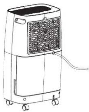
natural_image
Line drawing of a portable air conditioner unit with wheels and ventilation grille (no text or symbols)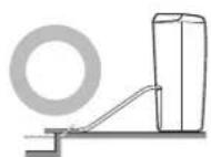
7. WARTUNG
natural_image
Line drawing of a portable air conditioner unit with visible fan and wheels (no text or symbols)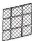
natural_image
Illustration of a person cleaning a solar panel with a spray gun (no text or symbols)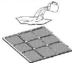
natural_image
Illustration of a container pouring liquid into a grid-patterned surface (no text or symbols)natural_image
Diagram showing two views of a grid-patterned panel or tray structure, with an arrow indicating transformation (no text or symbols present)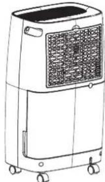
natural_image
Line drawing of a portable air conditioner unit with wheels and ventilation grille (no text or symbols)natural_image
Line drawing of a portable air conditioner unit with wheels and ventilation grille (no text or symbols)Abstand
BESCHRÄNKTE GARANTIE


VEILIGHEIDSWAARSCHUWINGEN
WAARSCHUWING AFVALVERWIJDERING
- Voorpaneel 2. Bedieningspaneel 3. Achterbehuizing
- Filterkast 5. Voorbehuizing 6. Watertank
- Zwenkwiel 8. Voedingskabel
OPTIONEEL
natural_image
Two abstract geometric shapes: a grid-patterned square and a twisted rope-like line (no text or symbols)4. HET VERZAMELDE WATER AFVOEREN
natural_image
Line drawing of an air conditioning unit with cooling panel and wheels (no text or symbols)natural_image
Technical line drawing of a mechanical component with a droplet symbol below (no text or labels)LET OP
natural_image
Technical line drawing of a rectangular device with a cross mark above it, no text or symbols presentnatural_image
Line drawing of a portable air conditioner unit with cooling fins and wheels (no text or symbols)6. DOORLOPENDE WATERAFVOER
natural_image
Line drawings of a portable air purifier with internal compartments and grid panels, plus a circular base (no text or symbols)natural_image
Illustration of a person cleaning a solar panel with a spray gun (no text or symbols)
natural_image
Illustration of a container pouring liquid into a bowl, with a grid of compartments below (no text or symbols)natural_image
Diagram showing two views of a grid-patterned panel or tray structure, with an arrow indicating transformation (no text or symbols present)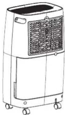
natural_image
Line drawing of a portable air conditioner unit with wheels and ventilation grille (no text or symbols)natural_image
Line drawing of a portable air purifier with control panel and wheels (no text or symbols)Vrije ruimte
8. PROBLEEMOPLOSSING


Caution, risk of fire, R290
AVVERTENZE DI SICUREZZA
natural_image
Line drawing of a portable air conditioner unit with cooling fins and wheels (no text or symbols)natural_image
Technical line drawing of a mechanical component with a droplet symbol below (no text or labels)NOTA
natural_image
Technical line drawing of a mechanical component with a cross symbol indicating a dislocation or assembly (no text or labels present)natural_image
Line drawing of an air conditioner unit with cooling fins and wheels, showing airflow direction arrows (no text or symbols)6. SCARICO ACQUA CONTINUO
natural_image
Line drawings of two identical air purifiers with ventilation grilles and wheels, shown from different angles (no text or symbols)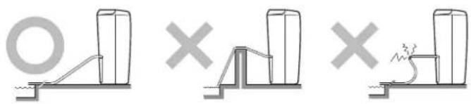
natural_image
Three diagrams showing different types of mechanical or structural configurations, including a ramp and a dam-like structure, with no visible text or symbols.7. MANUTENZIONE
natural_image
Technical line drawings of an air purifier with internal components and a grid-patterned panel (no text or symbols)natural_image
Two diagrams showing a person spraying water onto a grid of rectangular panels, with no text or symbols present.natural_image
Diagram showing a grid-patterned panel being processed into a rack-mounted air purifier (no text or symbols present)natural_image
Line drawing of a portable air conditioner unit with wheels and ventilation grille (no text or symbols)Spazi liberi


natural_image
Two abstract geometric shapes: a grid-patterned square and a curved line with loop (no text or symbols)natural_image
Line drawing of an air conditioner unit with cooling fins and wheels, showing airflow direction arrows (no text or symbols)natural_image
Technical line drawing of a mechanical component with a droplet symbol at the bottom (no text or labels)NOTA
natural_image
Technical line drawing of a mechanical component with a cross symbol indicating a tool or fixture (no text or labels present)natural_image
Line drawing of a portable air conditioner unit with airflow arrows indicating movement (no text or symbols)6. DESAGÜE CONTINUO DE AGUA
natural_image
Illustration of a person using a tool to spread or spray over a grid-patterned surface (no text or symbols)
natural_image
Illustration of a container pouring liquid into a tray with grid pattern (no text or symbols)natural_image
Diagram showing a grid-patterned air conditioner unit being processed into a flat panel, with an adjacent air heater unit (no text or symbols present)natural_image
Line drawing of a portable air purifier with control panel and wheels (no text or symbols)Espacio libre


AVISOS DE SEGURANÇA
natural_image
Line drawing of a portable air conditioner unit with cooling fins and wheels (no text or symbols)natural_image
Technical line drawing of a mechanical component with a droplet symbol below (no text or labels)NOTA
natural_image
Technical line drawing of a mechanical component with a cross symbol indicating a disassembled part (no text or labels present)natural_image
Illustration of a person using a telescope to spread a grid on a solar panel (no text or symbols)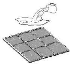
natural_image
Illustration of a container pouring liquid into a grid-patterned surface (no text or symbols)3. Monte o filtro de ar
Insira o filtro na grelha suavemente e coloque a grelha de entrada no lugar certo.
natural_image
Line drawing of a portable air conditioner unit with wheels and ventilation grille (no text or symbols)Afastamento


Caution, risk of fire, R290
SIKKERHEDSADVARSLER
natural_image
Two abstract geometric shapes: a grid-patterned square and a twisted rope-like line (no text or symbols)5. T∅MNING AF UDL∅BSBEHOLDEREN
natural_image
Line drawing of a portable air conditioner unit with cooling fins and wheels (no text or symbols)natural_image
Technical line drawing of a mechanical component with no visible text or symbolsThe image is too blurry to recognize any text content.
BEMÆRK
natural_image
Technical line drawing of a rectangular electronic component with a cross symbol above it (no text or labels)natural_image
Line drawing of an air conditioning unit with cooling fan and wheels (no text or symbols)6. L∅BENDE VANDUDL∅B
For at rengøre legemet
natural_image
Line drawings of an air purifier with internal components and a grid-patterned panel, plus a circular base (no text or symbols)2. Rengør luftfilteret
natural_image
Illustration of a person cleaning a solar panel array (no text or symbols)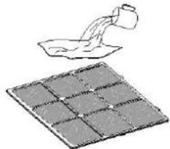
natural_image
Illustration of a container pouring liquid into a grid-patterned surface (no text or symbols)3. Genmonter luftfilteret
natural_image
Two technical diagrams showing a grid-patterned panel being cut down into a rectangular plate (no text or symbols)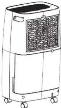
natural_image
Line drawing of a portable air conditioner unit with control panel and wheels (no text or symbols)natural_image
Line drawing of a portable air conditioner unit with wheels and ventilation grille (no text or symbols)Afstand
HVAD DER IKKE DÆKKES:


Caution, risk of fire, R290
SÄKERHETSFÖRESKRIFTER
natural_image
Line drawing of an air purifier with cooling unit and directional arrows indicating airflow or movement (no text or symbols)natural_image
Technical line drawing of a mechanical component with a droplet symbol below (no text or labels)OBSERVERA
natural_image
Technical line drawing of a mechanical component with a cross symbol indicating a dislocation or assembly (no text or labels present)natural_image
Line drawing of a portable air purifier with cooling unit and ventilation slots (no text or symbols)6. KONTINUERLIG DRÄNERING AV VATTEN
natural_image
Technical line drawings of a portable air conditioner unit with internal components and a grid-patterned cover (no text or symbols)natural_image
Illustration of a person using a tool to spray or spray over a grid-patterned surface (no text or symbols)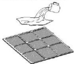
natural_image
Illustration of a container pouring liquid into a grid on a surface (no text or symbols)natural_image
Diagram showing two views of a grid-patterned metal tray with an arrow indicating transformation (no text or symbols)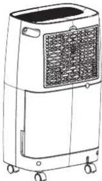
natural_image
Line drawing of a portable air conditioner unit with wheels and ventilation grille (no text or symbols)natural_image
Line drawing of a portable air conditioner unit with wheels and ventilation grille (no text or symbols)Avstånd