7519 - Router Porter-Cable - Free user manual and instructions
Find the device manual for free 7519 Porter-Cable in PDF.
| Product Type | Plunge router |
| Brand | Porter-Cable |
| Model | 7519 |
| Category | Professional router |
| Composition | Motor model 75192 + Base model 75361 |
| No-load speed | 21,000 rpm (fixed) |
| Collet capacity | 12.7 mm (1/2 in) with collet; adapters for 6.35 mm (1/4 in) and 9.525 mm (3/8 in) |
| Power supply | 120 V ~, 60 Hz, 11 A (estimate) |
| Double insulation | Yes (class II) |
| Soft start | Yes (minimizes torque reaction) |
| Overload protection | Built-in thermal circuit breaker in switch |
| Switch | Rocker on/off switch with circuit breaker |
| Max. recommended cutting depth | Up to 3/4 in depending on material |
| Max. bit diameter at 21,000 rpm | 2 1/2 in (63.5 mm) |
| Weight (approximate) | 5.0 kg (11 lb) |
| Dimensions (L x W x H) | 18 x 18 x 25 cm |
| Housing material | Reinforced plastic and metal |
| Maintenance | Clean air passages with compressed air; brush inspection after 100 h |
| Warranty | 1 year (professional tools) |
| Included accessories | 1/2 in collet, wrenches, no guide provided |
Frequently Asked Questions - 7519 Porter-Cable
User questions about 7519 Porter-Cable
0 question about this device. Answer the ones you know or ask your own.
Ask a new question about this device
Download the instructions for your Router in PDF format for free! Find your manual 7519 - Porter-Cable and take your electronic device back in hand. On this page are published all the documents necessary for the use of your device. 7519 by Porter-Cable.
USER MANUAL 7519 Porter-Cable
To learn more about Porter-Cable visit our website at:
http://www.porter-cable.com
PORTER+CABLE
ESPANOL: PÁGINA 17
FRANÇAISE : PAGE 31
Double Insulated Routers

MODEL 7518
Consisting of:
MODEL 75182 Motor
MODEL 75361 Base
MODEL 7519
Consisting of:
MODEL 75192 Motor
MODEL 75361 Base
IMPORTANT
Please make certain that the person who is to use this equipment carefully reads and understands these instructions before starting operations.
The Model and Serial No. plate is located on the main housing of the tool. Record these numbers in the spaces below and retain for future reference.
Model No.
Type
Serial No.
TABLE OF CONTENTS
IMPORTANT SAFETY INSTRUCTIONS 2
SAFETY GUIDELINES - DEFINITIONS 3
GENERAL SAFETY RULES 4
ADDITIONAL SPECIFIC SAFETY RULES 6
FUNCTIONAL DESCRIPTION 8
ASSEMBLY 9
OPERATION 9
TROUBLESHOOTING. 13
MAINTENANCE 14
SERVICE 14
ACCESSIONS 15
WARRANTY. 16
ESPANOL. 17
FRANÇAIS 31
IMPORTANT SAFETY INSTRUCTIONS
WARNING
Read and understand all warnings and operating instructions before using any tool or equipment. When
using tools or equipment, basic safety precautions should always be followed to reduce the risk of personal injury. Improper operation, maintenance or modification of tools or equipment could result in serious injury and property damage. There are certain applications for which tools and equipment are designed. Porter-Cable strongly recommends that this product NOT be modified and/or used for any application other than for which it was designed.
If you have any questions relative to its application DO NOT use the product until you have written Porter-Cable and we have advised you.
Online contact form at www.porter-cable.com
Postal Mail: Technical Service Manager
Porter-Cable
4825 Highway 45 North
Jackson, TN 38305
Information regarding the safe and proper operation of this tool is available from the following sources:
Power Tool Institute
1300 Sumner Avenue, Cleveland, OH 44115-2851
www.powertoolinstitute.org
National Safety Council
1121 Spring Lake Drive, Itasca, IL 60143-3201
American National Standards Institute, 25 West 43rd Street, 4 floor, New York, NY 10036 www.ansi.org ANSI 01.1Safety Requirements for Woodworking Machines, and the U.S. Department of Labor regulations www.osha.gov
SAVE THESE INSTRUCTIONS!
SAFETY GUIDELINES - DEFINITIONS
It is important for you to read and understand this manual. The information it contains relates to protecting YOUR SAFETY and PREVENTING PROBLEMS. The symbols below are used to help you recognize this information.

DANGER
indicates an imminently hazardous situation which, if not avoided, will result in death or serious injury.
WARNING
indicates a potentially hazardous situation which, if not avoided, could result in death or serious injury.
CAUTION
indicates a potentially haz ard ous situation which, if not avoided, may result in minor or mod er ate injury.
CAUTION
used without the safety alert symbol indicates potentially hazardous situation which, if not avoided, may result in property damage.
CALIFORNIA PROPOSITION 65
WARNING
Some dust created by power sanding, sawing, grinding, drilling, and other construction activities contains chemicals
known (to the State of California) to cause cancer, birth defects or other reproductive harm. Some examples of these chemicals are:
- lead from lead-based paints
- crystalline silica from bricks and cement and other masonry products
- arsenic and chromium from chemically-treated lumber
Your risk from these exposures varies, depending on how often you do this type of work. To reduce your exposure to these chemicals: work in a well ventilated area, and work with approved safety equipment, al ways wear NIOSH/OSHA approved, properly fitting face mask or respirator when using such tools.
GENERAL SAFETY RULES
WARNING
Read all instructions. Failure to follow all instructions listed below may result in electric or serious injury. The term "power tool" in all its listed below refers to your mains-operated tool or battery-operated (cordless) power tool.

shock, fire and/or serious injury. The term "power tool" in all of the warnings listed below refers to your mains-operated (corded) power tool or battery-operated (cordless) power tool.
SAVE THESE INSTRUCTIONS
1) Work area safety
a) Keep work area clean and well lit. Cluttered or dark areas invite accidents.
b) Do not operate power tools in explosive atmospheres, such as in the presence of flammable liquids, gases or dust. Power tools create sparks which may ignite the dust or fumes.
c) Keep children and bystanders away while operating a power tool. Distractions can cause you to lose control.
2) Electrical safety
a) Power tool plugs must match the outlet. Never modify the plug in any way. Do not use any adapter plugs with earthed (grounded) power tools. Unmodified plugs and matching outlets will reduce risk of electric shock.
b) Avoid body contact with earthed or grounded surfaces such as pipes, radiators, ranges and refrigerators. There is an increased risk of electric shock if your body is earthed or grounded.
c) Do not expose power tools to rain or wet conditions. Water entering a power tool will increase the risk of electric shock.
d) Do not abuse the cord. Never use the cord for carrying, pulling or unplugging the power tool. Keep cord away from heat, oil, sharp edges or moving parts. Damaged or entangled cords increase the risk of electric shock.
e) When operating a power tool outdoors, use an extension cord suitable for outdoor use. Use of a cord suitable for outdoor use reduces the risk of electric shock.
3) Personal safety
a) Stay alert, watch what you are doing and use common sense when operating a power tool. Do not use a power tool while you are tired or under the influence of drugs, alcohol or medication. A moment of inattention while operating power tools may result in serious personal injury.
b) Use safety equipment. Always wear eye protection. Safety equipment such as dust mask, non-skid safety shoes, hard hat, or hearing protection used for appropriate conditions will reduce personal injuries.
c) Avoid accidental starting. Ensure the switch is in the off-position before plugging in. Carrying power tools with your finger on the switch or plugging in power tools that have the switch on invites accidents.
d) Remove any adjusting key or wrench before turning the power tool on. A wrench or a key left attached to a rotating part of the power tool
GENERAL SAFETY RULES continued
may result in personal injury.
e) Do not overreach. Keep proper footing and balance at all times. This enables better control of the power tool in unexpected situations.
f) Dress properly. Do not wear loose clothing or jewelry. Keep your hair, clothing and gloves away from moving parts. Loose clothes, jewelry or long hair can be caught in moving parts.
g) If devices are provided for the connection of dust extraction and collection facilities, ensure these are connected and properly used. Use of these devices can reduce dust-related hazards.
4) Power tool use and care
a) Do not force the power tool. Use the correct power tool for your application. The correct power tool will do the job better and safer at the rate for which it was designed.
b) Do not use the power tool if the switch does not turn it on and off. Any power tool that cannot be controlled with the switch is dangerous and must be repaired.
c) Disconnect the plug from the power source before making any adjustments, changing accessories, or storing power tools. Such preventive safety measures reduce the risk of starting the power tool accidentally.
d) Store idle power tools out of the reach of children and do not allow persons unfamiliar with the power tool or these instructions to operate the power tool. Power tools are dangerous in the hands of untrained users.
e) Maintain power tools. Check for misalignment or binding of moving parts, breakage of parts and any other condition that may affect the power tools operation. If damaged, have the power tool repaired before use. Many accidents are caused by poorly maintained power tools.
f) Keep cutting tools sharp and clean. Properly maintained cutting tools with sharp cutting edges are less likely to bind and are easier to control.
g) Use the power tool, accessories and tool bits etc., in accordance with these instructions and in the manner intended for the particular type of power tool, taking into account the working conditions and the work to be performed. Use of the power tool for operations different from those intended could result in a hazardous situation.
5) Service
a) Have your power tool serviced by a qualified repair person using only identical replacement parts. This will ensure that the safety of the power tool is maintained.
ADDITIONAL SPECIFIC SAFETY RULES
- HOLD POWER TOOL BY INSULATED GRIPPING SURFACES WHEN PERFORMING AN OPERATION WHERE THE CUTTING TOOL MAY CONTACT HIDDEN WIRING OR ITS OWN CORD. Contact with a "live" wire will make exposed metal parts of the tool "live" and shock the operator.
- USE CLAMPS OR OTHER PRACTICAL WAY TO SECURE AND SUPPORT THE WORKPIECE TO A STABLE PLATFORM. Holding the work by hand or against your body is unstable and may lead to loss of control.
- DISCONNECT TOOL FROM POWER SOURCE before making adjustments or changing bits.
- TIGHTEN COLLET NUT securely to prevent the bit from slipping.
- USE A CLAMP or some other device to hold the workpiece rigidly in position and clear the path of the tool of obstructions.
- PROVIDE CLEARANCE under workpiece for router bit when through-cutting.
- CHECK TO SEE THAT THE CORD will not "hang up" during routing operation.
- CLEAR THE ROUTER BIT AREA before starting motor.
- MAINTAIN FIRM GRIP on router to resist starting torque.
- KEEP HANDS CLEAR OF BIT when motor is running to prevent personal injury.
- KEEP CUTTING PRESSURE CONSTANT. Do not overload motor.
- LET THE MOTOR COME TO A COMPLETE STOP before putting the tool down.
- NEVER TOUCH router bits after use. They may be extremely hot.
- NEVER TIGHTEN COLLET NUT without a bit.
- DO NOT USE ROUTER BITS with a diameter in excess of 2 - 1 / 2'' at RPM above 13,000. Router bits up to 3 - 1 / 2'' in diameter can be used when speed control is set for 13,000 RPM or less.
- ALWAYS KEEP CHIP SHIELD clean and in place.
- AVOID "CLIMB-CUTTING" (see "Using The Router" section in this manual). "Climb-cutting" increases the chance for loss of control resulting in possible personal injury.
- DO NOT HAND-HOLD THE ROUTER IN AN UPSIDE-DOWN OR HORIZONTAL POSITION. The motor can separate from the base if not properly attached according to the instructions.
- Wear eye and hearing protection. Always use safety glasses. Everyday eyeglasses are NOT safety glasses. USE CERTIFIED SAFETY EQUIPMENT. Eye protection equipment should comply with ANSI Z87.1 standards. Hearing equipment should comply with ANSI S3.19 standards.
- WARNING Use of this tool can generate and disburse dust or other airborne particles, including wood dust, crystalline silica dust and asbestos dust. Direct particles away from face and body. Always operate tool in well ventilated area and provide for proper dust removal. Use dust collection system wherever possible. Exposure to the dust may cause serious and permanent respiratory or other injury, including silicosis (a serious lung disease), cancer, and death. Avoid breathing the dust, and avoid prolonged contact with dust. Allowing dust to get into your mouth or eyes, or lay on your skin may promote absorption of harmful material. Always use properly fitting NIOSH/OSHA approved respiratory protection appropriate for the dust exposure, and wash exposed areas with soap and water.
SYMBOL
DEFINITION
V . volts
A. amperes
Hz hertz
W . . . . . . . . . . . . . . . . . . . . . . . . . . . . . . . . . . . . . . . . . . . . . . . . . . . . . . . . . . . . . . . . . . . . . . . w a t t s
kW kilowatts
F farads
F . microfarads
I............litres
g . grams
kg kilograms
bar . bars
Pa . . . . . . . . . . . . . . . . . . . . . . . . . . . . . . . . . . . . . . . . . . . . . . . . . . . . . . . . . . . .. pascals
h hours
min minutes
s....seconds
no-load speed
.../min or ...min-1……… Revolutions or reciprocations per minute
--- or d.c. direct current
or a.c. ...alternating current
2 two-phase alternating current
2N two-phase alternating current with neutral
3 three-phase alternating current
3N three-phase alternating current with neutral
- rated current of the appropriate fuse-link in amperes
time-lag miniature fuse-link where X is the symbol for
the time/current characteristic, as given in IEC 60127
protective earth
class II tool
IPXX. IP symbol
MOTOR
Many Porter-Cable tools will operate on either D.C., or single phase 25 to 60 cycle A.C. current and voltage within plus or minus 5 percent of that shown on the specification plate on the tool. Several models, however, are designed for A.C. current only. Refer to the specification plate on your tool for proper voltage and current rating.
CAUTION
Do not operate your tool on a current on which the voltage is not within correct limits. Do not operate tools rated A.C.
only on D.C. current. To do so may seriously damage the tool.
EXTENSION CORD SELECTION
If an extension cord is used, make sure the conductor size is large enough to prevent excessive voltage drop which will cause loss of power and possible motor damage. A table of recommended extension cord sizes will be found in this section. This table is based on limiting line voltage drop to 5 volts (10 volts for 230 volts) at 150% of rated amperes.
If an extension cord is to be used outdoors, it must be marked with the suffix W-A or W following the cord type designation. For example - SJTW-A to indicate it is acceptable for outdoor use.
SAVE THESE INSTRUCTIONS!
| RECOMMENDED EXTENSION CORD SIZES FOR USE WITH PORTABLE ELECTRIC TOOLS | |||||||||
| Length of Cord in Feet | |||||||||
| 115V 25 Ft. 50 Ft. | 100 Ft. 150 Ft. 200 Ft. | 300 Ft. 400 Ft. 500 Ft. | |||||||
| 230V 50 Ft. 100 Ft. | 300 Ft. 400 Ft. | 600 Ft. 800 Ft. 1000 Ft. | |||||||
| Nameplate Ampere Rating | 0-2 18 | 16 14 14 12 | 2 12 | ||||||
| 2-3 18 | 14 12 12 10 | 8 | |||||||
| 3-4 18 | 12 12 10 10 | 8 | |||||||
| 4-5 18 | 12 10 10 8 | 8 | |||||||
| 5-6 18 | 10 10 | 8 | 6 | ||||||
| 6-8 18 | 6 6 | 6 | |||||||
| 8-10 | 14 | 10 | 8 | 8 | 6 | 6 | 4 | ||
| 10-12 | 14 | 8 | 8 | 6 | 6 | 4 | 4 | ||
| 12-14 | 12 | 8 | 6 | 6 | 6 | 4 | 2 | ||
| 14-16 | 12 | 8 | 6 | 6 | 4 | 4 | 2 | ||
| 16-18 | 12 | 8 | 6 | 4 | 4 | 2 | 2 | ||
| 18-20 | 12 | 8 | 6 | 4 | 4 | 2 | 2 | ||
CARTON CONTENTS
- Routerer
- Open-end wrenches (2)
FUNCTIONAL DESCRIPTION
Model 7518 Porter-Cable Router incorporates a speed control that provides operating speeds from 10,000 RPM to 21,000 RPM, to handle the most demanding router applications in various materials.
Model 7519 Porter-Cable Router is designed for continuous, rugged operations to handle the most demanding routing applications at 21,000 RPM.
ASSEMBLY
NOTE: This tool is shipped completely assembled. No assembly time or tools are required.
OPERATION
SELECTING THE BIT
Models 7518 and 7519 accommodate bits with 1/2 diameter shanks that are installed directly into the power unit collet. Collets are available that will allow the use of bits having 1/4 or 3/8 diameter shanks.
CAUTION
DON'T USE router bits with a diameter in excess of 2^1/2 " except when using Model 75182 motor set for either
10,000 or 13,000 RPM. Router bits with a diameter up to 3'' may be used with the 75182 motor operating in the 10,000 or 13,000 RPM speeds. Router bits with a diameter up to 3^1/2'' may be used with the 75182 motor operating in the 10,000 RPM speed.
INSTALLING AND REMOVING THE BIT
WARNING
Disconnect tool from power source.
- To remove motor unit from base unit:
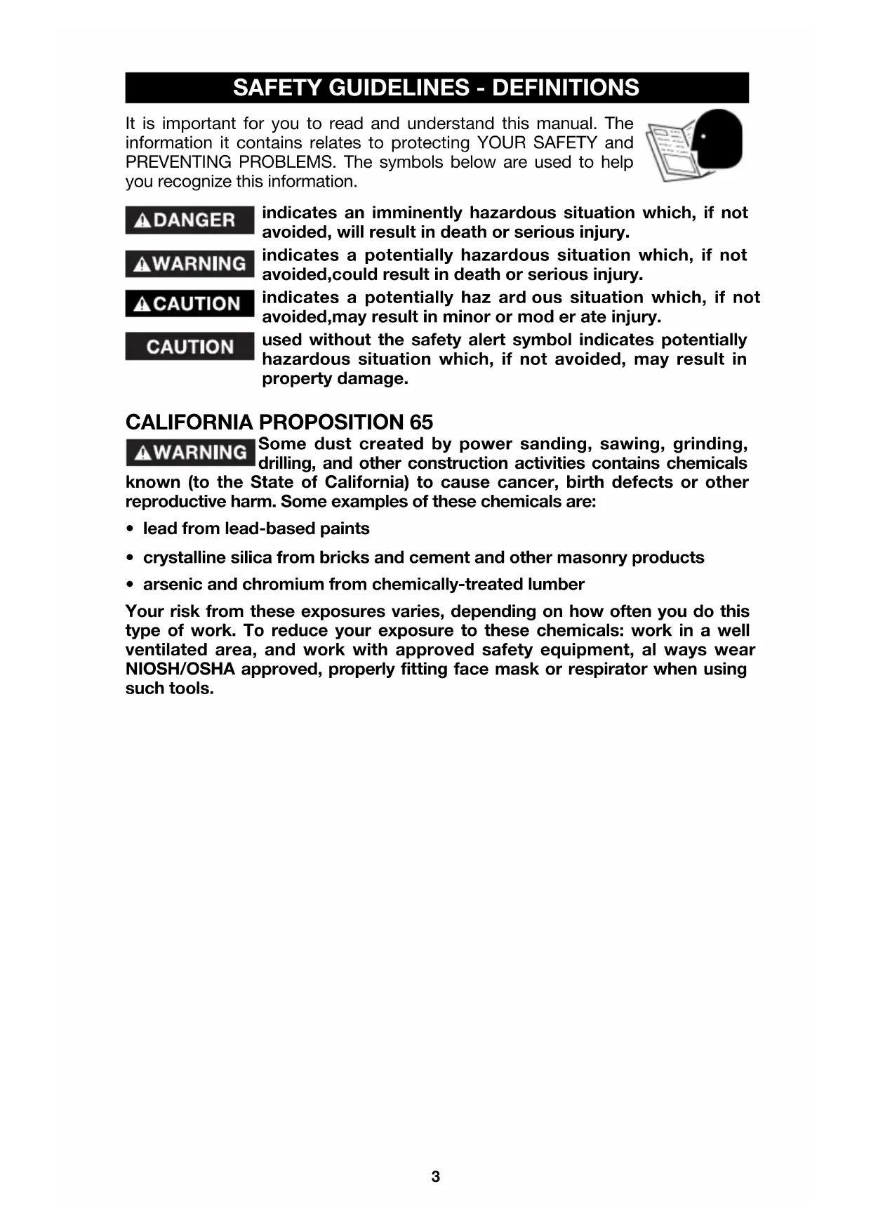
(a) Open the clamp (A) Fig. 1.
(b) While holding base, turn motor unit COUNTERCLOCKWISE until lower pin (B) in motor housing is disengaged from groove in base.
(c) Lift power unit free from base unit.
- Clean and insert shank of bit into collet at least 3/4 . If shank
"bottoms" in router, then back it out approximately 1/16" to allow proper tightening.
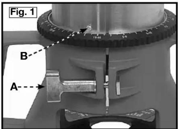
- Lay the power unit on its side on a bench with the collet pointing AWAY from
you.
- Place one wrench on flats on chuck with the opposite end of the wrench resting on the bench to your left, Fig. 2.
- Place other wrench on collet and tighten COUNTERCLOCKWISE as shown in Fig. 2. TIGHTEN SECURELY.
- To remove the bit, reverse the above procedure. If bit does not remove easily, tap the colle
CAUTION
Avoid possible damage to collet. Never tighten collet without a bit.
INSTALLING THE MOTOR
WARNING
Disconnect tool from power source.
- Loosen the clamp screw (A), Fig. 1, to allow the power unit to be set in the base unit.
- Insert motor unit into base aligning lower pin (B) with groove in base.
- Rotate motor unit CLOCKWISE into base until upper guide pins are rigidly set in the groove of the base.
- Tighten clamp screw firmly.
ADJUSTING DEPTH OF CUT
Disconnect tool from power source.
- Loosen clamp screw (A) Fig. 3.
- While holding base (E), turn motor unit (F), Fig. 3, COUNTERCLOCKWISE until the tip of the bit is above bottom surface of base.
- Set router on flat wood surface.
- Turn motor unit (F), Fig. 3, CLOCKWISE until bit touches the wood surface.
- Tighten clamp screw (A) Fig.3.
- Rotate depth adjusting ring (B), Fig. 3, until the zero-line (C) is opposite the index line (D) on the housing.
- Loosen clamp screw (A), Fig. 3.
- Tip the router so bit is clear of the wood surface. Turn motor unit (F), Fig. 3, CLOCKWISE until the index line (D) on the motor housing reaches the desired depth indicated on the ring.
- Tighten clamp screw (A), Fig. 3, firmly.
NOTE: Setting the index line to 14 on the ring means the cutting edge of the bit is exposed 14 below the base.
CONNECTING TO POWER SOURCE
CAUTION
Before connecting router to power source ALWAYS MAKE SURE SWITCH IS IN THE "OFF" POSITION. Also check that
the power circuit is the same as that shown on specification plate of the router.
TO START AND STOP ROUTER

Before starting the router make sure bit is clear of workpiece and foreign objects. Also keep firm grip on router torque.
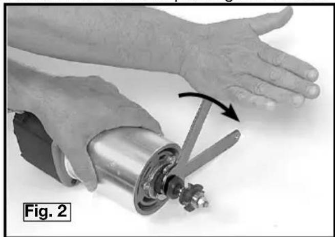
The router is started and stopped by depressing the rocker switch (A), Fig. 4, into the "ON" or "OFF" position.

To avoid personal injury or damage to finished work always allow the motor to come to a COMPLETE STOP before
setting it down.

Fig. 4
OVERLOAD PROTECTION
Model 7518 is equipped with an overload protector that will shut motor off if prolonged overload conditions are encountered.
If the motor stops during use: (1) depress rocker switch (A), Fig. 4, into the "OFF" position; (2) determine cause of overload (i.e. dull bit, low voltage, excessive feed rate, etc.) and correct before continuing; (3) restart router following the instructions in TO START AND STOP ROUTER.
Model 7519 is equipped with a thermal-type circuit breaker incorporated into the ON/OFF rocker switch (A), Fig. 4. This circuit breaker will turn the switch "OFF" if prolonged overload conditions are encountered.
If the circuit breaker "trips", switching the motor "OFF": (1) determine cause of the overload (i.e. dull bit, low voltage, excessive feed rate, etc.) and correct before continuing; (2) allow router to cool for three minutes; and, (3) restart router following the instructions in TO START AND STOP ROUTER.
SOFT START
Model 7518 and 7519 have a "Soft Start" feature designed to minimize startup reaction torque.
SPEED CONTROL (Model 7518 only)
The speed control is located as shown in Fig. 4. Five operating speeds from 10,000 RPM to 21,000 RPM are available by moving the speed selector knob (B), Fig. 4. It is recommended that the speed be set prior to engaging the router bit into work. Should it be necessary to change the speed after work has begun, stop router, remove router clear of work, and adjust speed setting.
USING THE ROUTER
IMPORTANT: Before using your router, consider the kind and total amount of material to be removed. Depending on the material, it may be necessary to make more than one cut to avoid overloading the motor. Before beginning the cut on the actual workpiece, it is advisable to make a sample cut on a piece of scrap lumber. This will show exactly how the cut will look as well as enable you to check dimensions.
CAUTION
Always be sure the work is rigidly clamped or otherwise secured before making a cut.
IMPORTANT: Before using your router, consider the kind and total amount of material to be removed. Depending on the material, it may be necessary to make more than one cut to avoid overloading the motor. Before beginning the cut on the actual workpiece, it is advisable to make a sample cut on a piece of scrap lumber. This will show exactly how the cut will look as well as enable you to check dimensions.
Always be sure the work is rigidly clamped or otherwise secured before making a cut.
Generally speaking, when working on a bench, the workpiece should be held on the bench by wood clamps. When routing edges, the router should be held firmly down and against the work by both handles.
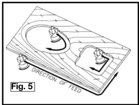
Since the cutter rotates clockwise (when viewing router from top), the router should be moved from left to right as you stand facing the work (see Fig. 5). When working on the inside of a templet, move router in clockwise direction. When working on the outside of a templet, move router in a counterclockwise direction.
WARNING
Avoid "Climb-Cutting" (cutting
in direction opposite that shown in Fig. 5), "Climb-Cutting" increases the chance for loss of control resulting in possible personal injury. When "Climb-Cutting" is required (backing around a corner), exercise extreme caution to maintain control of router.
The speed and depth of cut will depend largely on the type of material being
worked upon. Keep the cutting pressure constant but do not crowd the router so the motor speed slows excessively. It may be necessary on exceptionally hard woods or problem materials to make more than one pass at various settings to get the desired depth of cut.
When making cuts on all four edges of the workpiece, it is advisable to have the first cut on the end of the piece across the grain. Thus, if chipping of wood occurs at the end of a cut, it will be removed when making the next cut parallel with the grain.
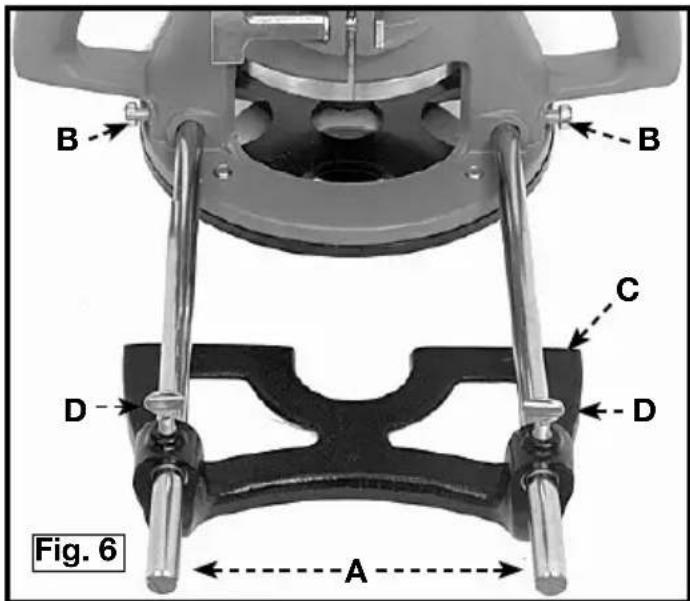
THE EDGE GUIDE
An edge guide is available as an accessory to aid in routing operations such as: straight edge planing, parallel grooving, dato or slotting operations.
To assemble, insert guide rods (A) in holes in base, Fig. 6, and secure with screws (B). The guide (C) is adjusted on the rods and secured in desired position with thumb screws (D)
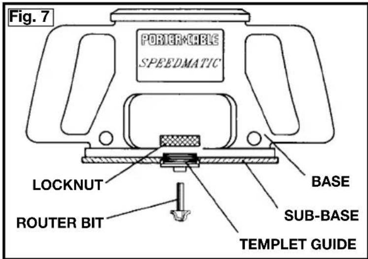
TEMPLATGUIDES
A wide variety of templet guides are available for use in pattern and templet routing operations. Fig. 7 shows a typical combination bit, templet guide, and locknut.
WARNING
Disconnect the tool from the power source.
To install, insert templet guide in center hole in router base and secure in place with the locknut.
NOTE: Before connecting the router to the power source, install, the bit, adjust depth of cut, and rotate the router chuck by hand to be sure the bit or the collet do not contact the templet guide.
TROUBLESHOOTING
For assistance with your tool, visit our website at www.porter-cable.com for a list of service centers or call the Porter-Cable help line at 1-800-487-8665.
MAINTENANCE
KEEP TOOL CLEAN
Periodically blow out all air passages with dry compressed air. All plastic parts should be cleaned with a soft damp cloth. NEVER use solvents to clean plastic parts. They could possibly dissolve or otherwise damage the material.
WARNING
Wear ANSI Z87.1 safety glasses while using compressed air.
FAILURE TO START
Should your tool fail to start, check to make sure the prongs on the cord plug are making good contact in the outlet. Also, check for blown fuses or open circuit breakers in the line.
BRUSH INSPECTION (If applicable)
For your continued safety and electrical protection, brush inspection and replacement on this tool should ONLY be performed by an AUTHORIZED PORTER-CABLE SERVICE STATION or a PORTER-CABLEDELTA FACTORY SERVICE CENTER.
At approximately 100 hours of use, take or send your tool to your nearest authorized Porter-Cable Service Station to be thoroughly cleaned and inspected. Have worn parts replaced and lubricated with fresh lubricant. Have new brushes installed, and test the tool for performance.
Any loss of power before the above maintenance check may indicate the need for immediate servicing of your tool. DO NOT CONTINUE TO OPERATE TOOL UNDER THIS CONDITION. If proper operating voltage is present, return your tool to the service station for immediate service.
SERVICE
REPLACEMENT PARTS
Use only identical replacement parts. For a parts list or to order parts, visit our website at servicenet.porter-cable.com. You can also order parts from your nearest factory-owned branch, or by calling our Customer Care Center at 1-800-223-7278 to receive personalized support from highly-trained technicians.
SERVICE AND REPAIRS
All quality tools will eventually require servicing and/or replacement of parts. For information about Porter-Cable, its factory-owned branches, or an Authorized Warranty Service Center, visit our website at www.porter-cable.com or call our Customer Care Center at 1-800-223-7278. All repairs made by our service centers are fully guaranteed against defective material and workmanship. We cannot guarantee repairs made or attempted by others.
You can also write to us for information at PORTER-CABLE, 4825 Highway 45 North, Jackson, Tennessee 38305 - Attention: Product Service. Be sure to include all of the information shown on the nameplate of your tool (model number, type, serial number, etc.).
ACCESSIONS
A complete line of accessories is available from your Porter-Cable-Delta Supplier, Porter-Cable-Delta Factory Service Centers, and Porter-Cable Authorized Service Stations. Please visit our Web Site www.porter-cable.com for a catalog or for the name of your nearest supplier.
WARNING
Since accessories other than those offered by Porter-Cable-Delta have not been tested with this product, use
of such accessories could be hazardous. For safest operation, only Porter-Cable-Delta recommended accessories should be used with this product.
WARRANTY
PORTER-CABLE LIMITED ONE YEAR WARRANTY
Porter-Cable warrants its Professional Power Tools for a period of one year from the date of original purchase. We will repair or replace at our option, any part or parts of the product and accessories covered under this warranty which, after examination, proves to be defective in workmanship or material during the warranty period. For repair or replacement return the complete tool or accessory, transportation prepaid, to your nearest Porter-Cable Service Center or Authorized Service Station. Proof of purchase may be required. This warranty does not apply to repair or replacement required due to misuse, abuse, normal wear and tear or repairs attempted or made by other than our Service Centers or Authorized Service Stations.
ANY IMPLIED WARRANTY, INCLUDING THE IMPLIED WARRANTYES OF MERCHANTABILITY AND FITNESS FOR A PARTICULAR PURPOSE, WILL LAST ONLY FOR ONE (1) YEAR FROM THE DATE OF PURCHASE.
To obtain information on warranty performance please write to: PORTER-CABLE CORPORATION, 4825 Highway 45 North, Jackson, Tennessee 38305; Attention: Product Service. THE FOREGOING OBLIGATION IS PORTER-CABLE'S SOLE LIABILITY UNDER THIS OR ANY IMPLIED WARRANTY AND UNDER NO CIRCUMSTANCES SHALL PORTER-CABLE BE LIABLE FOR ANY INCIDENTAL OR CONSEQUENTIAL DAMAGES. Some states do not allow limitations on how long an implied warranty lasts or the exclusion or limitation of incidental or consequential damages, so the above limitation or exclusion may not apply to you.
This warranty gives you specific legal rights and you may also have other legal rights which vary from state to state.
Copyright © 2005 Porter-Cable
ENGLISH: PAGE 1
FRANÇAISE : PAGE 31
El Correo Postal: Technical Service Manager Porter-Cable
4825
Jackson,
Highway
TN
45
38305
North
Power Tool Institute
1300 Sumner Avenue, Cleveland, OH 44115-2851
www.powertoolinstitute.org
National Safety Council
1121 Spring Lake Drive, Itasca, IL 60143-3201
American National Standards Institute, 25 West 43rd Street, 4 floor, New York, NY 10036 www.ansi.org ANSI 01.1 Safety Requirements for Woodworking Machines, and the U.S. Department of Labor regulations www.osha.gov
PARA INSTALAR Y REMOVER LA BROCA
PRECAUCION
Copyright © 2005 Porter-Cable
ENGLISH: PAGE 1
ESpañOL: PÁGINA 17
Courrier Postal: Technical Service Manager
Porter-Cable
4825
Highway
45
North
Jackson,
38305
Power Tool Institute
1300 Sumner Avenue, Cleveland, OH 44115-2851
www.powertoolinstitute.org
National Safety Council
1121 Spring Lake Drive, Itasca, IL 60143-3201
American National Standards Institute, 25 West 43rd Street, 4 floor, New York, NY 10036
www.ansi.org ANSI 01.1Safety Requirements for Woodworking Machines, and the
MESURES DE SECURITE - DÉFINITIONS
CONSERVEZ CES INSTRUCTIONS!
RÉGLES GÉNÉRALES SUR LA SÉCURITÉ
A VERTISSEMENT
CONSERVEZ CES INSTRUCTIONS!
MOTEUR
CONSERVEZ CES INSTRUCTIONS!
CONTENUS DE BOITE
- Toupie
- Clés (2)