PCE6430 - Router Porter-Cable - Free user manual and instructions
Find the device manual for free PCE6430 Porter-Cable in PDF.

| Product Type | Laminate Trimmer (Router) |
| Brand | Porter-Cable |
| Model | PCE6430 |
| Supply Voltage | 120 V, 60 Hz |
| Rated Current | 5 A |
| No-Load Speed | 30,000 rpm |
| Collet Diameter | 6.4 mm (1/4 in) |
| Max Cutter Diameter | 25.4 mm (1 in) |
| Max Depth of Cut per Pass | 12.7 mm (0.5 in) |
| Precision Adjustment | Graduations in 1/64 in (0.4 mm) |
| Edge Guide | Included, for straight and curved cuts |
| Quick Release System | Quick release tabs for motor removal |
| Switch | Sliding On/Off Switch |
| Lighting | LED Indicator |
| Motor Type | Universal (AC) |
| Maintenance | Clean with dry compressed air and mild soap |
| Safety | ANSI Z87.1 eye protection, respiratory protection, hearing protection |
| Warranty | 3-year limited, 1-year free service, 90-day satisfaction guarantee |
| Included Accessories | Spindle Wrench (17 mm), Edge Guide |
| Country of Manufacture | China |
Frequently Asked Questions - PCE6430 Porter-Cable
User questions about PCE6430 Porter-Cable
0 question about this device. Answer the ones you know or ask your own.
Ask a new question about this device
Download the instructions for your Router in PDF format for free! Find your manual PCE6430 - Porter-Cable and take your electronic device back in hand. On this page are published all the documents necessary for the use of your device. PCE6430 by Porter-Cable.
USER MANUAL PCE6430 Porter-Cable
natural_image
Illustration of a portable tower crane with 'PORTER + CABLE' branding, no text or symbols on the device itselfInstruction manual
▲ DANGER indicates an imminently hazardous situation which, if not avoided, will result in death or serious injury.
⚠ WARNING indicates a potentially hazardous situation which, if not avoided, could result in death or serious injury.
CAUTION indicates a potentially haz ard ous situation which, if not avoided, may result in minor or moderate injury.
NOTICE: used without the safety alert symbol indicates potentially hazardous situation which, if not avoided, may result in property damage.

WARNING
To reduce the risk of injury, read the instruction manual.
GENERAL POWER TOOL SAFETY WARNINGS
WARNING
Read all safety warnings and all instructions Failure to follow the warnings and instructions may result in electric shock, fire and/or serious injury.
SAVE ALL WARNINGS AND INSTRUCTIONS FOR FUTURE REFERENCE
The term “power tool” in the warnings refers to your mains-operated (corded) power tool or battery-operated (cordless) power tool.
1) WORK AREA SAFETY
a) Keep work area clean and well lit. Cluttered or dark areas invite accidents.
b) Do not operate power tools in explosive atmospheres, such as in the presence of flammable liquids, gases or dust. Power tools create sparks which may ignite the dust or fumes.
c) Keep children and bystanders away while operating a power tool. Distractions can cause you to lose control.
2) ELECTRICAL SAFETY
a) Power tool plugs must match the outlet. Never modify the plug in any way. Do not use any adapter plugs with earthed (grounded) power tools. Unmodified plugs and matching outlets will reduce risk of electric shock.
b) Avoid body contact with earthed or grounded surfaces such as pipes, radiators, ranges and refrigerators. There is an increased risk of electric shock if your body is earthed or grounded.
c) Do not expose power tools to rain or wet conditions. Water entering a power tool will increase the risk of electric shock.
d) Do not abuse the cord. Never use the cord for carrying, pulling or unplugging the power tool. Keep cord away from heat, oil, sharp edges or moving parts. Damaged or entangled cords increase the risk of electric shock.
e) When operating a power tool outdoors, use an extension cord suitable for outdoor use. Use of a cord suitable for outdoor use reduces the risk of electric shock.
f) If operating a power tool in a damp location is unavoidable, use a ground fault circuit interrupter (GFCI) protected supply. Use of a GFCI reduces the risk of electric shock.
3) PERSONAL SAFETY
a) Stay alert, watch what you are doing and use common sense when operating a power tool. Do not use a power tool while you are tired or under the influence of drugs, alcohol or medication. A moment of inattention while operating power tools may result in serious personal injury.
b) Use personal protective equipment. Always wear eye protection. Protective equipment such as dust mask, non-skid safety shoes, hard hat, or hearing protection used for appropriate conditions will reduce personal injuries.
c) Prevent unintentional starting. Ensure the switch is in the off position before connecting to power source and/or battery pack, picking up or carrying the tool. Carrying power tools with your finger on the switch or energizing power tools that have the switch on invites accidents.
d) Remove any adjusting key or wrench before turning the power tool on. A wrench or a key left attached to a rotating part of the power tool may result in personal injury.
e) Do not overreach. Keep proper footing and balance at all times. This enables better control of the power tool in unexpected situations.
f) Dress properly. Do not wear loose clothing or jewelry. Keep your hair, clothing and gloves away from moving parts. Loose clothes, jewelry or long hair can be caught in moving parts.
g) If devices are provided for the connection of dust extraction and collection facilities, ensure these are connected and properly used. Use of dust collection can reduce dust-related hazards.
4) POWER TOOL USE AND CARE
a) Do not force the power tool. Use the correct power tool for your application. The correct power tool will do the job better and safer at the rate for which it was designed.
b) Do not use the power tool if the switch does not turn it on and off. Any power tool that cannot be controlled with the switch is dangerous and must be repaired.
c) Disconnect the plug from the power source and/or the battery pack from the power tool before making any adjustments, changing accessories, or storing power tools. Such preventive safety measures reduce the risk of starting the power tool accidentally.
d) Store idle power tools out of the reach of children and do not allow persons unfamiliar with the power tool or these instructions to operate the power tool. Power tools are dangerous in the hands of untrained users.
e) Maintain power tools. Check for misalignment or binding of moving parts, breakage of parts and any other condition that may affect the power tool's operation. If damaged, have the power tool repaired before use. Many accidents are caused by poorly maintained power tools.
f) Keep cutting tools sharp and clean. Properly maintained cutting tools with sharp cutting edges are less likely to bind and are easier to control.
g) Use the power tool, accessories and tool bits, etc. in accordance with these instructions, taking into account the working conditions and the work to be performed. Use of the power tool for operations different from those intended could result in a hazardous situation.
5) SERVICE
a) Have your power tool serviced by a qualified repair person using only identical replacement parts. This will ensure that the safety of the power tool is maintained.
ADDITIONAL SPECIFIC SAFETY RULES
ADDITIONAL SAFETY RULES FOR LAMINATE TRIMMER
- Hold power tool by insulated gripping surfaces, because the cutter may contact its own cord. Cutting a “live” wire may make exposed metal parts of the power tool “live” and shock the operator.
- Use clamps or another practical way to secure and support the workpiece to a stable platform. Holding the work by hand or against your body leaves it unstable and may lead to loss of control.
- Always follow the bit manufacturer's speed recommendations as some bit designs require specific speeds for safety or performance. If you are unsure of the proper speed or are experiencing any type of problem, contact the bit manufacturer.
• DO NOT CUT METAL. - Keep handles and gripping surfaces dry, clean, and free from oil and grease. This will enable better control of the tool.
- Maintain firm grip with both hands on laminate trimmer to resist starting torque.
- Keep hands away from cutting area. Never reach under the workpiece for any reason. Keep the laminate trimmer base firmly in contact with the workpiece when cutting. These precautions will reduce the risk of personal injury.
- Never run the motor unit when it is not inserted into the base. The motor is not designed to be handheld.
- Keep cutting pressure constant. Do not overload motor.
- Check to see that the cord will not snag or impede the trimming operation.
- Use sharp bits. Dull bits may cause the laminate trimmer to swerve or stall under pressure.
- Be sure that the bit is clear of the workpiece before starting the motor. If the bit is in contact with the workpiece when the motor starts, it could make the laminate trimmer jump, causing damage or injury.
- ALWAYS disconnect tool from power source before making adjustments or changing bits.
- Keep hands clear of bit when motor is running to prevent personal injury.
- NEVER touch the bit immediately after use. It may be extremely hot.
- Provide clearance under workpiece for bit when through-cutting.
- Tighten collet nut securely with provided wrench (17 mm) to prevent the bit from slipping.
-
Never tighten collet nut without a bit.
-
Not recommended for use in a router table.
- Avoid climb-cutting (cutting in direction opposite than shown in Figure 7). Climb-cutting increases the chance for loss of control resulting in possible injury. When climb-cutting is required (backing around a corner), exercise extreme caution to maintain control of trimmer. Make smaller cuts and remove minimal material with each pass.
- Be sure that the motor has stopped completely before you lay the laminate trimmer down. If the bit head is still spinning when the tool is laid down, it could cause injury or damage.
- Do not press spindle lock button while the motor is running. Doing so can damage the spindle lock.
- Do not use AC only rated tools with a DC power supply. While the tool may appear to work, the electrical components of the AC rated tool are likely to fail and create a hazard to the operator.
- If cutting into existing walls or other blind areas where electrical wires may exist is unavoidable, disconnect all fuses or circuit breakers feeding this worksite.
- Always make sure the work surface is free from nails and other foreign objects. Cutting into a nail can cause the bit and the tool to jump and damage the bit.
- Never lay workpiece on top of hard surfaces like concrete, stone etc... Protruding cutting bit may cause tool to jump.
- Do not leave tool running. Operate tool only when hand-held.
- Air vents often cover moving parts and should be avoided. Loose clothes, jewelry or long hair can be caught in moving parts.
- An extension cord must have adequate wire size (AWG or American Wire Gauge) for safety. The smaller the gauge number of the wire, the greater the capacity of the cable, that is 16 gauge has more capacity than 18 gauge. An undersized cord will cause a drop in line voltage resulting in loss of power and overheating. When using more than one extension to make up the total length, be sure each individual extension contains at least the minimum wire size. The following table shows the correct size to use depending on cord length and nameplate ampere rating. If in doubt, use the next heavier gauge. The smaller the gauge number, the heavier the cord.
| Minimum Gauge for Cord Sets | ||||||
| Ampere Rating | Volts Total Length of Cord in Feet (meters) | |||||
| 120V 25 (7.6) 50 (15.2) 100 (30.5) | 150 (45.7) | |||||
| 240V 50 (15.2) 100 (30.5) 200 (61.0) 300 (91.4) | ||||||
| More Than | Not More Than | AWG | ||||
| 0 | 6 | 18 | 16 | 16 | 14 | |
| 6 | 10 | 18 | 16 | 14 | 12 | |
| 10 | 12 | 16 | 16 | 14 | 12 | |
| 12 | 16 | 14 | 12 | Not Recommended | ||
⚠ WARNING ALWAYS use safety glasses. Everyday eyeglasses are NOT safety glasses. Also use face or dust mask if cutting operation is dusty. ALWAYS WEAR CERTIFIED SAFETY EQUIPMENT:
• ANSI Z87.1 eye protection (CAN/CSA Z94.3),
• ANSI S12.6 (S3.19) hearing protection,
• NIOSH/OSHA/MSHA respiratory protection.
WARNING Some dust created by power sanding, sawing, grinding, drilling, and other construction activities contains chemicals known to the State of California to cause cancer, birth defects or other reproductive harm. Some examples of these chemicals are:
- lead from lead-based paints,
• crystalline silica from bricks and cement and other masonry products, and
• arsenic and chromium from chemically-treated lumber.
Your risk from these exposures varies, depending on how often you do this type of work. To reduce your exposure to these chemicals: work in a well ventilated area, and work with approved safety equipment, such as those dust masks that are specially designed to filter out microscopic particles.
- Avoid prolonged contact with dust from power sanding, sawing, grinding, drilling, and other construction activities. Wear protective clothing and wash exposed areas with soap and water. Allowing dust to get into your mouth, eyes, or lay on the skin may promote absorption of harmful chemicals.
⚠ WARNING Use of this tool can generate and/or disperse dust, which may cause serious and permanent respiratory or other injury. Always use NIOSH/OSHA approved respiratory protection appropriate for the dust exposure. Direct particles away from face and body.
⚠ WARNING Always wear proper personal hearing protection that conforms to ANSI S12.6 (S3.19) during use. Under some conditions and duration of use, noise from this product may contribute to hearing loss.
- The label on your tool may include the following symbols. The symbols and their definitions are as follows:
V....volts A....amperes
Hz......hertz W......watts
min ...... minutes \~ or AC ......alternating
--- or DC ... direct current current
Class I Construction AC/DC ...alternating or (grounded) direct curr
☐......Class II Construction ^no ......no load (double insulated) speed
.../min ..... per minute n .....rated speed
BPM .... beats per minute ⊕ ....earthing
IPM .... impacts per minute terminal
RPM ....revolutions per minute ⚠️ ....safety alert symbol
sfpm ...... surface feet per minute
SAVE THESE INSTRUCTIONS
MOTOR
Be sure your power supply agrees with the nameplate marking. Voltage decrease of more than 10% will cause loss of power and overheating. PORTER-CABLE tools are factory tested; if this tool does not operate, check power supply.
NOTICE: Do not operate your tool on a current on which the voltage is not within correct limits. Do not operate tools rated A.C. only on D.C. current. To do so may seriously damage the tool.
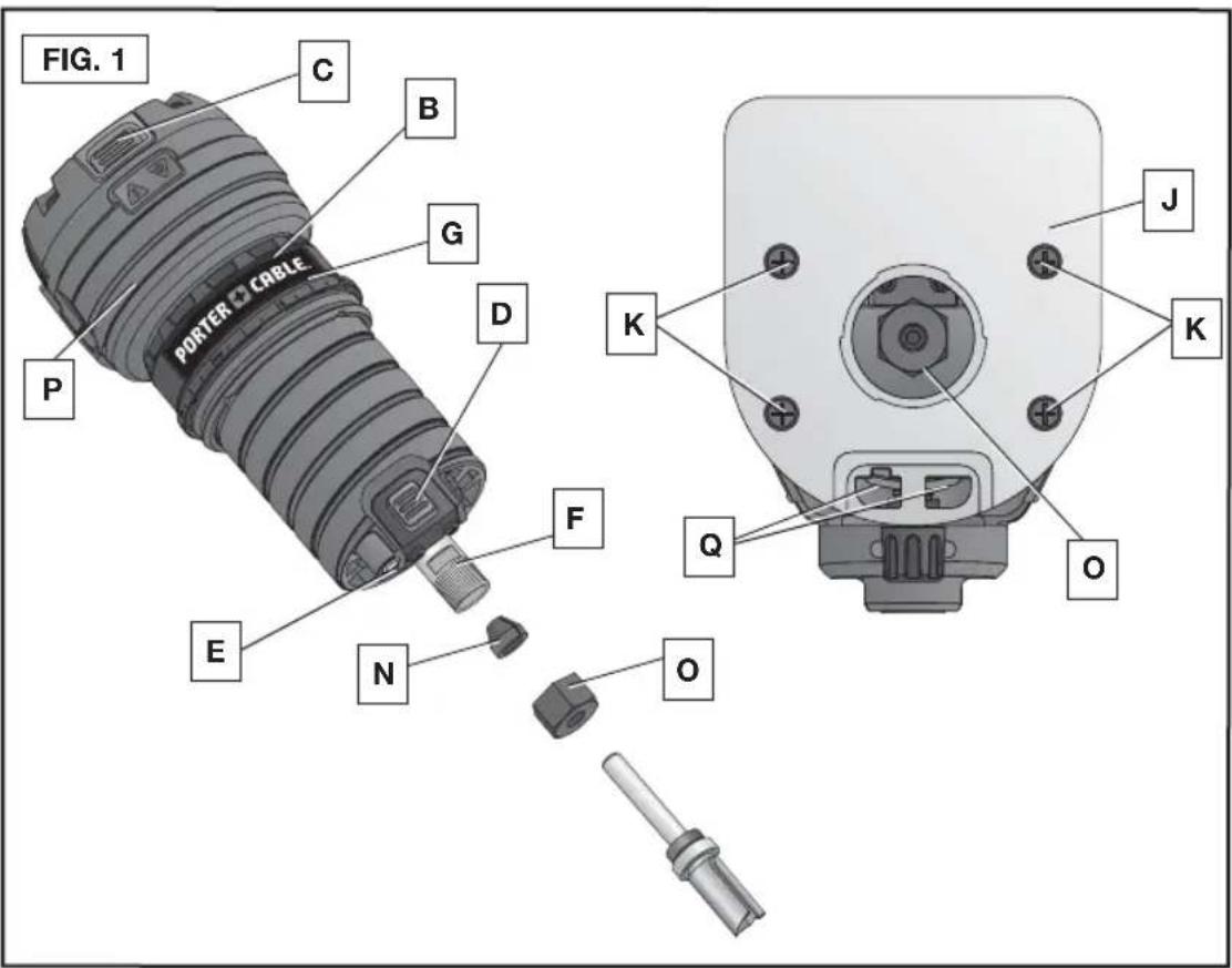
COMPONENTS (FIG. 1, 2)
WARNING
Never modify the power tool or any part of it. Damage or personal
injury could result.
A. Quick release tabs
B. Depth adjustment ring
C. On/off switch
D. Spindle lock button
E. LED light
F. Spindle
G. Micro adjustment scale
H. Locking lever
I. Base
J. Subbase
K. Sub-base screws
L. Guide pins
M. Locking lever adjustment screw
N. Collet
O. Collet nut
P. Motor unit
Q. Roller bearing/edge guide slot
R. Edge guide
S. Guide screw
T. Spindle wrench
text_image
FIG. 1 PORTER CABLE C B G D P E N F K J K Q O
text_image
FIG. 2 A L H I M S T J RINTENDED USE
This laminate trimmer is designed for professional flush and bevel trimming of laminated plastics and other similar materials that have a bonding agent too hard to be trimmed with ordinary tools.
DO NOT use under wet conditions or in presence of flammable liquids or gases.
This laminate trimmer is a professional power tool. DO NOT let children come into contact with the tool. Supervision is required when inexperienced operators use this tool.
OPERATION
WARNING To reduce the risk of injury, turn unit off and disconnect it from power source before installing and removing accessories, before adjusting or when making repairs. An accidental start-up can cause injury.
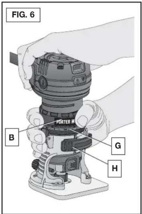
PROPER HAND POSITION (FIG. 6)
⚠ WARNING To reduce the risk of serious personal injury, ALWAYS use proper hand position as shown.
WARNING To reduce the risk of serious personal injury, ALWAYS hold securely in anticipation of a sudden reaction.
Proper hand position requires one hand on the motor base with the other hand on the motor cap.
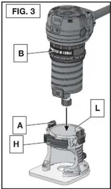
INSERTING THE MOTOR INTO THE FIXED BASE (FIG. 1-3)
-
Open the locking lever (H) on the base.
-
If the depth adjustment ring (B) is not on the motor, thread the depth adjustment ring (B) onto the motor until the ring is positioned as shown. Insert the motor into the base by aligning the groove in the back of the motor with the guide pins (L) on the base. Slide the motor down until the depth adjustment ring (B) snaps into place.
- Adjust the depth of cut by turning the depth adjustment ring (B). Refer to Adjusting the Depth of Cut.
- Close the locking lever (H) when the desired depth is achieved. For information on setting the cutting depth, Refer to Adjusting the Depth of Cut.
MOTOR QUICK RELEASE (FIG. 3)
- Open the locking lever (H) on the base.
- Grasp the base with one hand, depressing both quick release tabs (A).
- With the other hand, grasp and pull motor from the base.
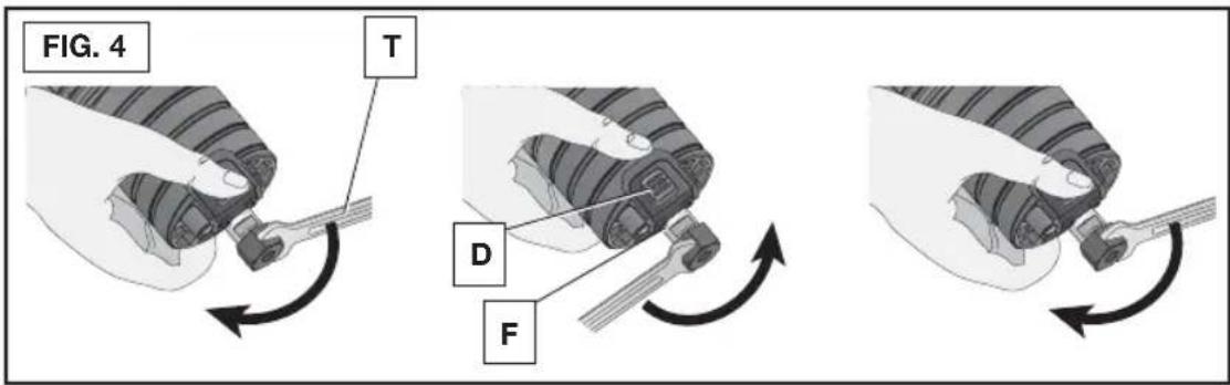
BIT INSTALLATION AND REMOVAL (FIG. 4)
SELECTING THE BIT
WARNING Projectile hazard. Only use bits with 1/4" (6.4 mm) shanks. Smaller shank bits will not be secure and could become loose during operation.
These laminate trimmers are equipped with a 1/4" (6.4 mm) diameter collet which accepts bits having 1/4" (6.4 mm) diameter shanks. Bits are available as an accessory.
WARNING Do not use bits with a diameter in excess of 1" (25.4 mm) in this tool.
text_image
FIG. 4 T D FINSTALLING THE BIT
NOTE: The bit shank and chuck should be clean and free of dust, wood residue and grease before assembling.
- Remove the motor unit from the base. Refer to Motor Quick Release (if needed).
- Clean and insert the bit shank into the collet until the end of the shank bottoms. Then withdraw the bit approximately 1/16" (1.6 mm).
- Press and hold the spindle lock button (D). Tighten the collet nut securely with the supplied 17 mm open-end wrench (T).
NOTE: As an alternative to the spindle lock button, a thin 10 mm wrench can be used on the flats of the spindle (F).
To remove the bit, reverse the procedure. If the bit will not remove easily, lightly tap the bit shank with a wrench.
text_image
FIG. 3 B A H LCOLLETS (FIG. 1)
NOTE: Never tighten the collet nut (O) without first installing a bit in it. Tightening an empty collet nut, even by hand, can damage the collet (N).
LOCKING LEVER ADJUSTMENT (FIG. 2)
Excessive force should not be used to clamp the locking lever (H). Using excessive force may damage the base.
When the locking lever is clamped, the motor should not move in the base.
Adjustment is needed if the locking lever will not clamp without excessive force or if the motor moves in the base after clamping.
ADJUSTING THE LOCKING LEVER'S CLAMPING FORCE
- Open the locking lever (H).
- Using a 2.5 mm hex wrench (not included) turn the locking lever adjustment screw (M) in small increments.
Turning the screw clockwise tightens the lever, while turning the screw counterclockwise loosens the lever.
CENTERING THE SUBBASE (FIG. 1)
If you need to adjust, change, or replace the subbase, a centering tool is recommended.
Refer to Accessories. The centering tool consists of a cone and a pin.
ADJUSTING THE SUBBASE
- Loosen but do not remove the subbase screws (K) so the subbase moves freely.
- Insert the pin into the collet and tighten the collet nut.
- Insert the motor into the base and clamp the locking lever on the base.
- Place a centering cone tool, available as an accessory at additional cost, on the pin and lightly press down on the cone until it stops. This will center the subbase.
- While holding down on the cone, tighten the subbase screws (K).
CONNECTING TO POWER SOURCE
CAUTION Before connecting tool to power source, check to see that the switch is in the "OFF" position. Also, check the power circuit to see that it is the same as that shown on specification plate of the tool.
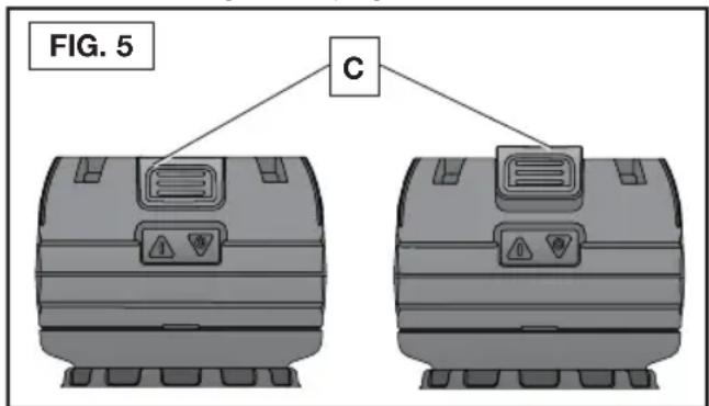
STARTING AND STOPPING THE MOTOR (FIG. 1, 5)
CAUTION Before starting the tool, clear the work area of all foreign objects. Also keep firm grip on tool to resist starting torque.
CAUTION To avoid personal injury and/or damage to finished work, always allow the power unit to come to a COMPLETE STOP before putting the tool down.
To turn unit on, pull the on/off switch (C) up. To turn the unit off, depress the switch back down into the motor housing. Refer to Figure 5.
text_image
FIG. 5 CADJUSTING THE DEPTH OF CUT (FIG. 6)
- Select and install the desired bit. Refer to Bit Installation and Removal.
- Assemble base to motor, ensuring base is attached to the depth adjustment ring. Place laminate trimmer on the work piece.
- Open the locking lever (H) and turn the depth adjustment ring (B) until the bit just touches the work piece. Turning the ring clockwise raises the cutting head while turning it counterclockwise lowers the cutting head.
- Turn the micro adjustment scale (G) clockwise until the 0 on the scale lines up with the pointer on the quick release tab (A).
- Turn the depth adjustment ring until the pointer lines up with desired depth of cut marking on the micro adjustment scale.
NOTE: Each mark on the adjustable scale represents a depth change of 1/64" or .015" (0.4 mm) and one full (360°) turn of the ring changes the depth 0.5" (12.7 mm).
- Close the locking lever (H) to lock the base.
text_image
FIG. 6 PORTER B G HUSING AN EDGE GUIDE (FIG. 2)
An edge guide is included with your laminate trimmer for use with non-piloted bits on curved or straight applications.
- Remove the screw (S) in the back of the base (I).
- Slide edge guide into edge guide slot (Q) on back of subbase (J). Tighten hardware
NOTE: To remove the edge guide, reverse the above procedure. After removing edge guide, always replace the screw (S) into the storage hole on the back of the base to prevent it from being lost.
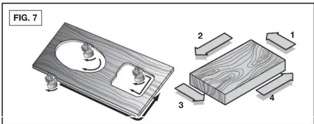
DIRECTION OF FEED (FIG. 7)
The direction of feed is very important when trimming and can make the difference between a successful job and a ruined project. The figures show the proper direction of feed for some typical cuts. A general rule to follow is to move the laminate trimmer in a counterclockwise direction on an outside cut and a clockwise direction on an inside cut.
text_image
FIG. 7 2 1 3 4SHAPING THE OUTSIDE EDGE OF A PIECE OF STOCK
- Shape the end grain, left to right
- Shape the straight grain side moving left to right
- Cut the other end grain side
- Finish the remaining straight grain edge
NOTE: Make several light passes instead of one heavy pass for better quality work.
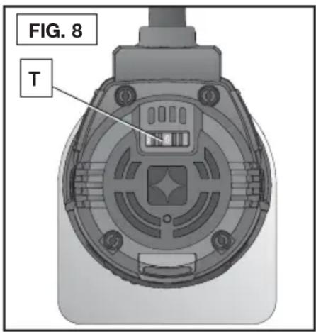
VARIABLE SPEED CONTROL (FIG. 8) (PCE6435 ONLY)
This laminate trimmer is equipped with a variable speed dial (T) with an infinite number of speeds between 16,000 and 30,000 RPM. Adjust the speed by turning the variable speed dial (T).
NOTICE: In low and medium speed operation, the speed control prevents the motor speed from decreasing. If you expect to hear a speed change and continue to load the motor, you could damage the motor by overheating. Reduce the depth of cut and/or slow the feed rate to prevent tool damage.
The laminate trimmer is equipped with electronics to monitor and maintain the speed of the tool while cutting.
text_image
FIG. 8 TSPEED SELECTION CHART
| DIAL SETTING APPROX. RPM | |
| 1 16,000 | |
| 2 19,300 | |
| 3 21,400 | |
| 4 23,700 | |
| 5 26,400 | |
| 6 30,000 | |
The speeds in this chart are approximate and are for reference only. Your laminate trimmer may not exactly produce the speed listed for the dial setting.
WARNING Always follow the bit manufacturer's speed recommendations as some bit designs require specific speeds for safety or performance.
If you are unsure of the proper speed or are experiencing any type of problem, contact the bit manufacturer.
MAINTENANCE
⚠ WARNING To reduce the risk of injury, turn unit off and disconnect it from power source before installing and removing accessories, before adjusting or when making repairs. An accidental start-up can cause injury.
REPAIRS
For assistance with your tool, visit our website at www.portercable.com for a list of service centers, or call the PORTER-CABLE Customer Care Center at (888) 848-5175.
CLEANING
WARNING Periodically blowing dust and chips out of the motor housing using clean, dry compressed air is a suggested maintenance procedure. To reduce the risk of serious personal injury, ALWAYS wear ANSI Z87.1 safety glasses while using compressed air.
⚠ WARNING When cleaning, use only mild soap and a damp cloth on plastic parts. Many household cleaners contain chemicals which could seriously damage plastic. Also, do not use gasoline, turpentine, lacquer, paint thinner, dry cleaning fluids or similar products which may seriously damage plastic parts. NEVER let any liquid get inside the tool; NEVER immerse any part of the tool into a liquid.
SERVICE
REPLACEMENT PARTS
Use only identical replacement parts. For a parts list or to order parts, visit our service website at servicenet.portercable.com. You can also order parts from your nearest PORTER-CABLE Factory Service Center or PORTER-CABLE Authorized Warranty Service Center. Or, you can call our Customer Care Center at (888) 848-5175.
SERVICE AND REPAIRS
All quality tools will eventually require servicing and/or replacement of parts. For information about PORTER-CABLE, its factory service centers or authorized warranty service centers, visit our website at www.portercable.com or call our Customer Care Center at (888) 848-5175. All repairs made by our service centers are fully guaranteed against defective material and workmanship. We cannot guarantee repairs made or attempted by others.
You can also write to us for information at PORTER-CABLE, 4825 Highway 45 North, Jackson, Tennessee 38305 - Attention: Product Service. Be sure to include all of the information shown on the nameplate of your tool (model number, type, serial number, etc.).
ACCESSORIES
A complete line of accessories is available from your PORTER-CABLE Factory Service Center or a PORTER-CABLE Authorized Warranty Service Center. Please visit our Web Site www.portercable.com for a catalog or for the name of your nearest supplier.
WARNING Since accessories other than those offered by PORTER-CABLE have not been tested with this product, use of such accessories could be hazardous. For safest operation, only PORTER-CABLE recommended accessories should be used with this product.
THREE YEAR LIMITED WARRANTY
PORTER-CABLE will repair, without charge, any defects due to faulty materials or workmanship for three years from the date of purchase. This warranty does not cover part failure due to normal wear or tool abuse. For further detail of warranty coverage and warranty repair information, visit www.portercable.com or call (888) 848-5175. This warranty does not apply to accessories or damage caused where repairs have been made or attempted by others. This warranty gives you specific legal rights and you may have other rights which vary in certain states or provinces.
In addition to the warranty, PORTER-CABLE tools are covered by our:
1 YEAR FREE SERVICE: PORTER-CABLE will maintain the tool and replace worn parts caused by normal use, for free, any time during the first year after purchase.
90 DAY MONEY BACK GUARANTEE: If you are not completely satisfied with the performance of your PORTER-CABLE Power Tool, Laser, or Nailer for any reason, you can return it within 90 days from the date of purchase with a receipt for a full refund – no questions asked.
LATIN AMERICA: This warranty does not apply to products sold in Latin America. For products sold in Latin America, see country specific warranty information contained in the packaging, call the local company or see website for warranty information.
To register your tool for warranty service visit our website at www.portercable.com.
WARNING LABEL REPLACEMENT
If your warning labels become illegible or are missing, call (888) 848-5175 for a free replacement.

text_image
ADVERTENCIA PARA EL MANEJO SEGURO LEA EL MANUAL DE INSTRUCCIONES. SIEMPRE SE DEBERÁ LLEVAR LA PROTECCIÓN APROPIADA PARA LA VISTA Y PARA LAS VÍAS RESPIRATORIAS. AVERTISSEMENT À TITRE PRÉVENTIF, LIRE LE GUIDE. IL FAUT TOUJOURS PORTER DE L'ÉQUIPEMENT DE PROTECTION OCULAIRE ET RESPIRATOIRE APPROPRIÉ. ADVERTENCIA PARA EL MANEJO SEGURO LEA EL MANUAL DE INSTRUCCIONES. SIEMPRE SE DEBERÁ LLEVAR LA PROTECCIÓN APROPIADA PARA LA VISTA Y PARA LAS VÍAS RESPIRATORIAS. AVERTISSEMENT À TITRE PRÉVENTIF, LIRE LE GUIDE. IL FAUT TOUJOURS PORTER DE L'ÉQUIPEMENT DE PROTECTION OCULAIRE ET RESPIRATOIRE APPROPRIÉ.
text_image
WARNING TO REDUCE THE RISK OF INJURY, USER MUST READ INSTRUCTION MANUAL. ALWAYS USE PROPER EYE AND RESPIRATORY PROTECTION. AVERTISSEMENT: À TITRE PRÉVENTIF, LIKE LE GUIDE. PORTER-CABLE JACKSON, TENNESSEE 39105 U.S.A. MADE IN CHINA PCEXXX TRIM ROUTER SER.MESURES DE SÉCURITÉ - DÉFINITIONS
text_image
FIG. 1 PORTER CABLE C B G D P E N F K J K Q O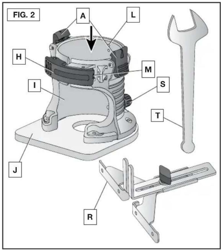
text_image
FIG. 2 A L H M I S T J RUSAGE PRÉVU
POSITION CORRECTE DES MAINS (FIG. 6)
text_image
FIG. 4 T D FINSTALLING THE BIT
NOTE: The bit shank and chuck should be clean and free of dust, wood residue and grease before assembling.
--- o DC ....corriente directa
alterna
text_image
FIG. 1 PORTER CABLE C B G D P E N F K J K Q O
text_image
FIG. 2 A L H I M S T J ROPERACIÓN
text_image
FIG. 4 T D FLocal D, Col. Obrera (55) 5588 9377
MERIDA, YUC
Calle 63 #459-A - Col. Centro (999) 928 5038
MONTERREY, N.L.
Av. Francisco I. Madero 831 Poniente - Col. Centro (818) 375 23 13
PUEBLA, PUE
17 Norte #205 - Col. Centro (222) 246 3714
QUERETARO, QRO
Av. San Roque 274 - Col. San Gregorio (442) 2 17 63 14
SAN LUIS POTOSI, SLP
The following are PORTER-CABLE trademarks for one or more power tools and accessories: a gray and black color scheme; a “four point star” design; and three contrasting/outlined longitudinal stripes.
PORTER CABLE.