FR350B - Stapler Porter-Cable - Free user manual and instructions
Find the device manual for free FR350B Porter-Cable in PDF.

| Product Type | Round Head Framing Nailer (Pneumatic Stapler) |
| Brand | Porter-Cable |
| Model | FR350B |
| Dimensions (H x W x D) | 375 x 120 x 550 mm |
| Weight | 3.25 kg |
| Power Source | Pneumatic (compressed air) |
| Operating Pressure | 4.8 to 8.3 bar (70 to 120 psi) |
| Maximum Supply Pressure | 12.6 bar (175 psi) |
| Air Consumption | 9.74 CFM for 100 cycles |
| Compatible Fastener Types | Round head framing nails, diameter 2.87 to 3.76 mm, length 50 to 90 mm, 22° angle, plastic collation |
| Magazine Capacity | 60 nails (2 full strips) |
| Air Inlet | 6.4 mm (1/4 in NPT) male quick connect |
| Activation Modes | Sequential and Contact (selectable) |
| Depth Adjustment | Tool-free adjustment wheel |
| Exhaust Deflector | 360° adjustable, 8 positions |
| Safety Features | Trigger lock, contact trigger, dry fire lockout (last four fasteners) |
| Lubrication Required | Porter-Cable pneumatic tool oil or SAE 20 non-detergent oil, 5 to 7 drops per day |
| Daily Maintenance | Drain compressor, clean magazine with air blow, check screws |
| Warranty | 3-year limited (material and workmanship defects) |
| Operating Temperature | Works in cold weather (reduce pressure to 5.5 bar) and hot weather (avoid direct sunlight) |
Frequently Asked Questions - FR350B Porter-Cable
User questions about FR350B Porter-Cable
0 question about this device. Answer the ones you know or ask your own.
Ask a new question about this device
Download the instructions for your Stapler in PDF format for free! Find your manual FR350B - Porter-Cable and take your electronic device back in hand. On this page are published all the documents necessary for the use of your device. FR350B by Porter-Cable.
USER MANUAL FR350B Porter-Cable
natural_image
Porter Cable electric shocker with black and white body, no visible text or symbols on the device itself.IMPORTANT SAFETY INSTRUCTIONS FOR PNEUMATIC TOOLS
SAVE THESE INSTRUCTIONS
WARNING:
When using any pneumatic tool, all safety precautions, as outlined below, should be followed to avoid the risk of death or serious injury. Read and understand all instructions before operating the tool.
DEFINITIONS - SAFETY GUIDELINES
The definitions below describe the level of severity for each signal word. Please read the manual and pay attention to these symbols.
DANGER:
Indicates an imminently hazardous situation which, if not avoided, will result in death or serious injury.
WARNING:
Indicates a potentially hazardous situation which, if not avoided, could result in death or serious injury.
CAUTION:
Indicates a potentially hazardous situation which, if not avoided, may result in minor or moderate injury.
NOTICE:
Used without the safety alert symbol indicates a situation which, if not avoided, may result in property damage.
- Actuating tool may result in flying debris, collation material, or dust which could harm operator's eyes.
Operator and others in work area MUST wear safety
glasses with side shields. These safety glasses must
conform to ANSI Z87.1 requirements (approved glases have “Z87” printed or stamped on them). It is the employer’s responsibility to enforce the use of eye protection equipment by the tool operator and other people in the work area. (Fig. A)

text_image
cation eyes.Fig. B
g 360°
natural_image
Diagram of a pressure regulator and filter unit (no text or labels)Fig. C
70 psi

text_image
le toFig. D
a
text_image
maximum bar) or- Minimize flying dust and debris by rotating exhaust to appropriate setting.
- Always wear appropriate personal hearing and other protection during use. Under some conditions, duration of use, noise from this product may contribute to hearing loss. (Fig. A)
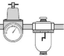
- Use only clean, dry, regulated air. Conden sation from an air compressor can rust and damage the internal workings of the tool. (Fig. B)
- Regulate air pressure. Use air pressure co with ratings on the nameplate of the tool. exceed 120 psi (8.3 bar).] Do not connect the tool to a compressor rated at over 175 psi. The tool operating pressure must never exceed 175 psi even in the event of regulator failure. (Fig. C)
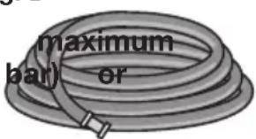
- Only use an air hose that is rated for working pressure of at least 150 psi (10.3 150% of the maximum system pressure, whichever is greater. (Fig. D)
- Do not use bottled gases to power this fuel compressed gases such as oxygen, carbon dioxide nitrogen, hydrogen, propane, acetylene or air are not for use with pneumatic tools. Never use combustible gases or any other reactive gas as a power source for this tool. Danger of explosion and/or serious personal injury may result. (Fig. E)
- Use couplings that relieve all pressure from the tool when it is disconnected from the power supply. Use hose connectors that shut off air supply from compressor when the tool is disconnected. (Fig. F)
- Disconnect tool from air supply when not in use. Always disconnect tool from air supply and remove fasteners from magazine before leaving the area of passing the tool to another operator. Do not carry tool to another work area in which changing location involves the use of scaffoldings, stairs, ladders, and the like, with air supply connected. Do not make adjustments remove magazine perform maintenance. Fig. G
adjustments, remove magazine, perform maintenance or clear jammed fasteners while connected air supply. If the contact trip is adjusted when the tool is connected to the air supply and nails are loaded, accidental discharge may occur. (Fig. G)
- Connect tool to air supply before loading fasteners to prevent an unintentional fastener discharge during connection. The tool driving mechanism may cycle when the tool is connected to the air supply. Do not load fasteners with the trigger or the contact trip depressed to prevent unintentional driving.
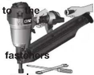
- Do not remove, tamper with, or otherwise cause the tool, trigger, or contact trip to become ino Do not tape or tie trigger or contact trip position. Do not remove spring from contact trip. Make daily inspections for free movement of trigger and contact trip. Uncontrolled discharge could result.
- Inspect tool before use. Do not operate a Fig. tool if any portion of the tool, trigger, or contact trip is inoperable, disconnected, altered, or not working properly. Leaking air, damaged parts or missing parts should be repaired or replaced before use. Refer to Repairs. (Fig. H)
- Do not alter or modify the tool in any way. (Fig. I)
• Always assume that the tool contains fasteners.
- Do not point the tool at co-workers or yourself at any time. No horseplay! Work safe! Respect the tool as a working implement. (Fig. J)
- Keep bystanders, children, and visitors away operating a power tool. Distractions can cause you to lose control. When tool is not in use, it should be locked in a safe place, out of the reach of children.
- Remove finger from trigger when not driving fasteners.
text_image
to the fasteners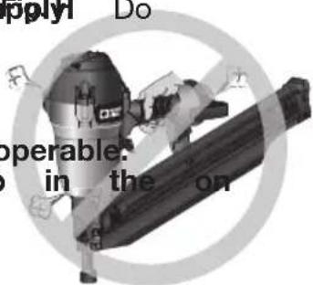
text_image
Apply! Do operable: in the on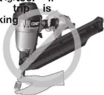
text_image
trip is king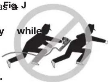
text_image
Fig. J while- Never carry tool with finger on trigger. Using the trigger lock-off will prevent accidental discharge. Accidental discharge could result.
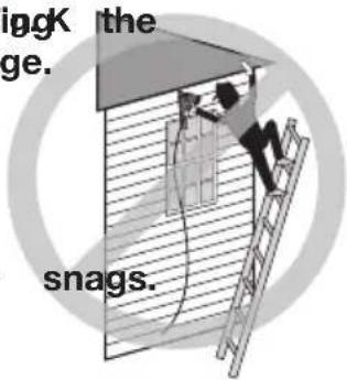
- Do not overreach. Maintain proper footing and balance at all times. Loss of balance may cause personal injury. (Fig. K)
- Make sure hose is free of obstructions or Entangled or snarled hoses can cause loss of balance or footing.
- Use the tool only for its intended use. Do not discharge fasteners into open air, concrete, stone, extremely hard woods, knots or any material too hard for the fastener to penetrate. Do not use the body of the tool or top cap as a hammer. Discharged fasteners may follow unexpected path and cause injury. (Fig. L)
• Always keep fingers clear of contact trip injury from inadvertent release of nails. (Fig. M)
• Refer to the Maintenance and Repairs se detailed information on the proper maintenance of the tool. - Always operate the tool in a clean, lighted sure the work surface is clear of any debris careful not to lose footing when working in elevated environments such as rooftops.
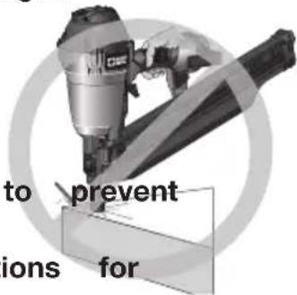
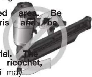
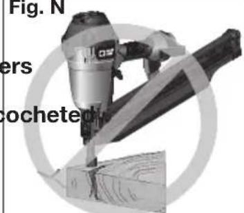
- Do not drive fasteners near edge of material. The workpiece may split causing the fastener to ricochet, injuring you or a co-worker. Be aware that the nail may
follow the grain of the wood (shiner), causing it to protrude unexpectedly from the side of the work material. Drive the nail perpendicular to the grain to reduce risk of injury. (Fig. N)
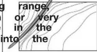
- Do not drive nails onto the heads of other fasteners
or with the tool at too steep an angle. Personal injury from strong recoil, jammed fasteners, or nails may result. (Fig. O)
- Be aware of material thickness when using the nailer. A protruding nail may cause injury.
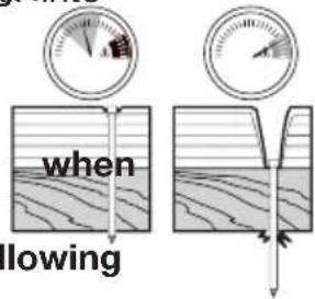
- Be aware that when the tool is being up pressures on the high end of its operating nails can be driven completely through thin soft work material. Make sure the pressure compressor is set so that nails are set in material and not pushed completely through. (Fig. P)
- Keep hands and body parts clear of immediate work area. Hold workpiece with clamps when necessary to keep hands and body out of potential harm. Be the workpiece is properly secured before pressing the nailer against the material. The contact trip may cause the work material to shift unexpectedly. (Fig. Q)
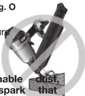
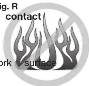
- Do not use tool in the presence of flammable gases or fumes. The tool may produce a spark
text_image
iggK the age. snags.Fig. L
text_image
to prevent ions forFig. M
text_image
red area. Be and be rial. The ricochet, I mayFig. N
text_image
Fig. N ers cochetedutilized at
text_image
range, or very in the into theFig. O
text_image
g. O re dust, that unable sparkcould ignite gases causing a fire. Driving a Fig1 Rnto another nail may also cause a spark. (Fig. R)
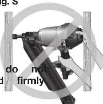
- Keep face and body parts away from back of the tool cap when working in restricted areas. Sudden recoil can result in impact to the body, especially nailing into hard or dense material. (Fig. S)
- Grip tool firmly to maintain control while allowing tool to recoil away from work surface as fastener is driven. In bump action mode (contact actuation mode). Fig. Q
If contact trip is allowed to recontact work before trigger is released an unwanted fastener be driven.
- Choice of triggering method is important. Check the manual for triggering options.
BUMP OR CONTACT ACTUATION TRIGGER
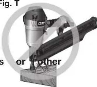
- When using the bump action trigger, be careful of unin tentional double fires resulting from tool recoil. Unwanted fasteners may be driven if the trip is allowed to accidentally re-contact the work surface. (Fig. T)
TO AVOID DOUBLE FIRES:
- Do not engage the tool against the with a strong force.
- Allow the tool to recoil fully after each actuation.
• Use sequential action trigger.
- When bump actuating the nailer, always keep tool in control. Inaccurate placement of tool can result in misdirected discharge of a fastener.
SEQUENTIAL ACTION TRIGGER
- When using the sequential action trigger, actuate the tool unless the tool is placed against the workpiece.
- DEPTH ADJUSTMENT: To reduce risk of serious injury from accidental actuation when attempting to adjust depth, ALWAYS:
- Disconnect air supply.
- Engage trigger lock
- Avoid contact with trigger during adjustments.
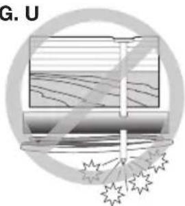
- Do not drive nails blindly into walls, floors work areas. Fasteners driven into live electrical wires, plumbing, or other types of obstructions can result in injury. (Fig. U)
- Stay alert, watch what you are doing and use common sense when operating a power tool. Do not use tool while tired or under the influence of drugs or alcohol. A moment of inattention while operating power tools may result in serious personal injury.
text_image
when lowing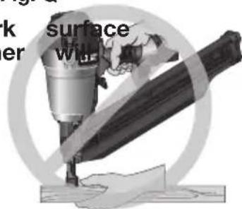
text_image
k surface er willFig. R contact
text_image
g. R contact work surfaceFig. S
text_image
g. S do not d firmlyFig. T
text_image
Fig. 1 s or otherFIG. U
natural_image
Illustration of a laptop with abstract wave patterns and a starburst graphic at the bottom (no text or symbols)⚠ WARNING: Use of this product may expose you to chemicals known to the State of California to cause cancer, birth defects and other reproductive harm. Avoid inhaling vapors and dust, and wash hands after using.
- Avoid prolonged contact with dust from power sanding, sawing grinding, drilling, and other construction activities. Wear protective clothing and wash exposed areas with soap and water. Allowing dust to get into your mouth, eyes, or lay on the skin may promote absorption of harmful chemicals.
⚠ WARNING: ☐ Use of this tool can generate and/or disburse dust, which may cause serious and permanent respiratory or other injury. Always use NIOSH/OSHA approved respiratory protection appropriate for the dust exposure. Direct particles away from face and body. Always operate tool in well-ventilated area and provide for proper dust removal. Use dust collection system wherever possible.
⚠ WARNING: ALWAYS USE SAFETY GLASSES. Everyday eyeglasses are NOT safety glasses. Also use face or dust mask if operation is dusty. ALWAYS WEAR CERTIFIED SAFETY EQUIPMENT:
• ANSI Z87.1 eye protection (CAN/CSA Z94.3).
• ANSI S12.6 (S3.19) hearing protection,
• NIOSH/OSHA respiratory protection.
Before operating this tool, carefully read and understand all instruction Important Safety Instructions.
save these instructions
| NAIL SPECIFICATIONS | |
| FR350B | |
| Nails 0.113"-0.148"(2.87-3.76 mm)diameter, plastic collated round head framing nails | |
| Lengths | 2"-3-1/2"(50-90 mm) |
| 22° | |
| Air Inlet | 1/4" NPT (6.4 mm) |
| NOTE: Use only PORTER-CABLE approved fasteners | |
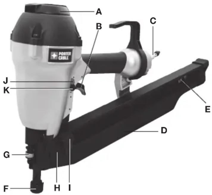
TOOL PARTS
Fig. 1
A. Exhaust deflector
B. Selectable trigger
C. Air Inlet with quick connect coupler
D. Magazine
E. Nail stop
F. Safety contact trip with No-mar pad
G. Depth adjustment wheel
H. Pusher release
I. Pusher
J. Trigger lock button
k. Mode selector button
text_image
PORTER CABLE A B C J K E D G F H IASSEMBLY
WARNING: Disconnect air line from tool, engage trigger lock and relax fasteners from magazine before making adjustments or personal injury result.
TRIGGER
⚠ WARNING: Keep fingers AWAY from the trigger when not driving fasteners to avoid accidental actuation. Never carry a tool with finger on the trigger. In bump action mode (contact actuation mode), the tool will drive a fastener if the contact trip is bumped while the trigger is depressed.
The FR350B is equipped with a selectable trigger. This trigger allows the operator to select either single sequential action trigger mode or bump action trigger mode. In accordance with the ANSI Standard SNT-101-2002, the trigger is assembled in the single sequential action trigger mode. To change the trigger mode, see Actuating Tool instructions in the Operation section of the manual. The selectable trigger also has a trigger lock button to keep the trigger locked at all times when the tool is not in use.
AIR FITTING
The tool is equipped with a 1/4" (6.4 mm) male quick connector coupling. A 3/8" (9.5 mm) male quick connector coupling is available from PORTER-CABLE and may be used when a 1/4" (6.4 mm) supply line is not available.
NOTE: A 3/8" (9.5 mm) supply line (and fittings) are required for maximum tool performance.
⚠ WARNING: Always use couplings that relieve all pressure from the tool when it is disconnected from the power supply. Always use hose connectors that shut off air supply from compressor when the tool is disconnected.
To install an air fitting
- Wrap the male end of the fitting with thread seal tape prior to assembly to eliminate air leaks.
- To install a 1/4" (6.4 mm) fitting: screw it directly into the air inlet and tighten firmly. NOTE: If an adapter is in the air inlet, remove it prior to inserting the fitting.
- To install a 3/8" (9.5 mm) fitting: screw the fitting into the 3/8" (9.5 mm) adapter and then into the air inlet of the tool and tighten firmly.
OPERATION
PREPARING THE TOOL
WARNING: Read the section titled Important Safety Instructions for Pneumatic
Tools at the beginning of this manual. Always wear eye and ear protection when operating this tool. Keep the nailer pointed away from yourself and others. For safe operation, complete the following procedures and checks before each use of the nailer.
NOTICE: To reduce the risk of damage to the tool, only use PORTER-CABLE pneumatic tool oil or a non-detergent SAE 20 weight oil. Oil with additives or detergent will damage tool parts.
- Before you use the nailer, be sure that the compressor tanks have been properly drained.
- Lubricate tool:
a. Use PORTER-CABLE pneumatic tool oil or a non-detergent S.A.E. 20 weight oil. DO NOT use detergent oil or additives as they will damage O-rings and rubber parts.
b. Use a filter when possible.
c. Add 5 to 7 drops of oil in the air fitting a least twice a day.
- Wear eye and ear protection.
- Ensure canister is empty of all fasteners.
- Check for smooth and proper operation of contact trip. Do not use tool if assembly is not functioning properly. NEVER tamper with the contact trip. NEVER use a tool that has the contact trip restrained in the actuated position.
- Check air supply: Ensure air pressure does not exceed recommended operating limits; 70 to 120 psi, (4.9 to 8.3 bar, 5 to 8.5 kg/cm ^2 ).
- Keep tool pointed away from yourself and others.
- Connect air hose.
- Check for audible leaks around valves and gaskets. Never use a tool that leaks or has damaged parts.
⚠ WARNING: To reduce the risk of personal injury, disconnect tool
supply and engage trigger lock before performing maintenance, clearing jammed fastener, leaving work area, moving tool to another location or handing the tool to another person.
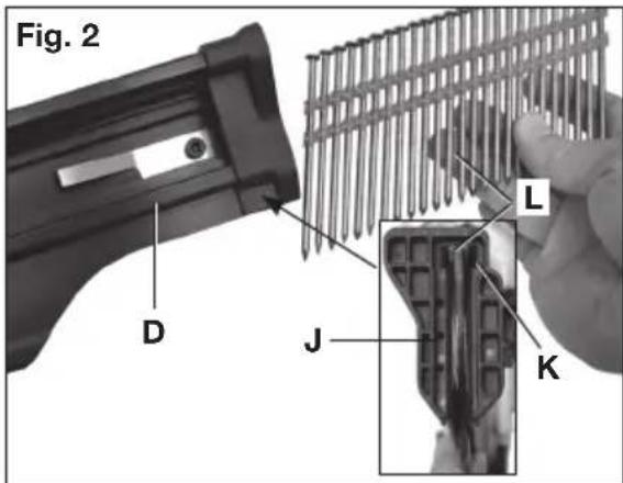
LOADING THE TOOL (FIG. 1-4)
⚠ WARNING: Keep the tool pointed away from yourself and others. Serious personal
injury may result.
⚠ WARNING: Never load nails with the contact trip or trigger activated. Personal
injury may result.
-
Read all Safety Warnings before using tool.
-
Connect the air supply to the tool.
-
Insert fasteners (L) into T-slot (K) on end cap of magazine (J) past the nail stop (E). NOTE: Magazine will hold two full fastener strips.
-
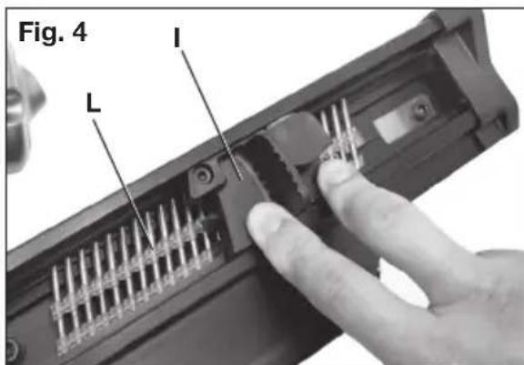
Pull pusher (I) back until the nail stop (E) falls behind the fasteners.
text_image
Fig. 2 D J L K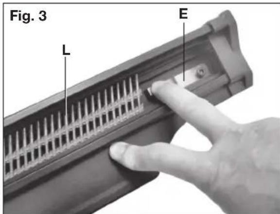
text_image
Fig. 3 L ENOTE: Do not allow the pusher to snap forward against the nail strip, allowing this to happen could damage the nail collation.
NOTE: This tool has a low nail lock out device which will not allow the tool to drive fasteners when the fastener quantity in the magazine is reduced to four. When unloading and loading the magazine always make sure these four nails have been removed from the magazine. If the nails are not removed from the magazine and the tool is reloaded and actuated, the nails will cause the tool to jam.
text_image
Fig. 4 L IACTUATING TOOL
⚠ WARNING: To reduce the risk of injury, ALWAYS wear proper eye ANSI Z87.1 (CAN/CSA Z94.3) and hearing protection ANSI S12.6 (S3.19) when operating this tool. The tool can be actuated using one of two modes: single sequential actuation trigger mode and contact actuation trigger mode.
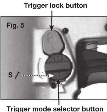
Single Sequential actuation trigger - ↗ (Fig. 5)
⚠ WARNING: Allow the tool to recoil off the work surface after actuation. If the contact trip remains depressed a nail will be driven each time the trigger is released and pulled, which could result in accidental actuation, possibly causing injury.
The sequential actuation trigger's intended use is for intermittent fastening where accurate fastener placement is desired.
To operate the tool in Single sequential actuation mode:
- Depress the contact trip firmly against the work surface.
text_image
Trigger lock button Fig. 5 S / Trigger mode selector button- Pull the trigger.
- Allow the tool to recoil from the work surface.
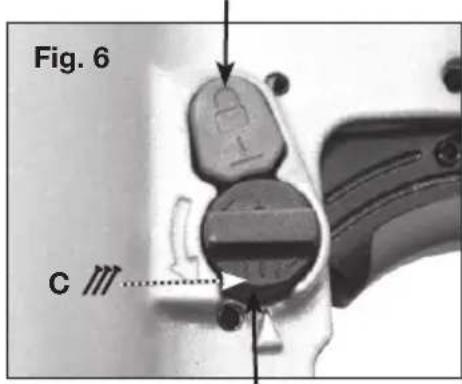
Contact actuation trigger - ∥ (Fig. 6)
The contact actuation trigger is intended for rapid fastening on flat, stationary surfaces.
Using the contact actuation trigger, two methods are available: place actuation and contact actuation.
To operate the tool using the PLACE ACTUATION method:
- Depress the contact trip against the work surface.
- Pull the trigger to drive the fastener.
- Allow the tool to recoil off the work surface
Trigger lock button
text_image
Fig. 6 CTrigger mode selector button
To operate the tool using the CONTACT ACTUATION method:
- Pull the trigger.
- Depress the contact trip against the work surface. As long as the trigger is pulled, the tool will drive a fastener every time the contact trip is depressed. This allows the user to rapidly drive multiple fastener in sequence.
Changing the Actuation Mode - 1
- Push the (red) trigger lock button down
- Rotate the (black) selectable trigger button counterclockwise
- Align the triangular indicator to the desired mode
• For Sequential Mode /
• For Contact Mode
- Then push the trigger lock button back up to the un-locked position.
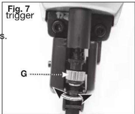
ADJUSTING DEPTH (FIG. 7)
⚠ WARNING: To reduce risk of serious injury from accidental actuation when attempting to adjust depth, ALWAYS:
- Disconnect air supply and engage lock.
- Avoid contact with trigger during adjustments.
The depth that the fastener is driven can be adjusted using the depth adjustment wheel (G). The depth of drive is factory adjusted. Test drive a fastener and check depth. If a change is desired:
text_image
Fig. 7 trigger s. G ......-
To drive the nail shallower, rotate the depth setting wheel (G) to the left.
-
To drive a nail deeper, rotate the depth setting wheel (G) to the right.
The adjustment knob has detents every full turn. Test drive another fastener and check depth. Repeat as necessary to achieve desired results. The amount of air pressure required will vary depending on the size of the fastener and the material being fastened. Experiment with the air pressure setting to determine the lowest setting that will consistently perform the job at hand.
CAUTION: Air pressure in excess of that required can cause premature wear and/or damage to the tool.
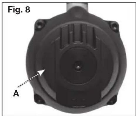
DIRECTIONAL EXHAUST DEFLECTOR (FIG. 8)
Adjust directional exhaust deflector (A), so the exhaust air blast will be directed away from the operator. The exhaust deflector provides sixteen detented positions for directing the exhaust blast away from the operator. Grasp the deflector and rotate it to the desired position for the current application.
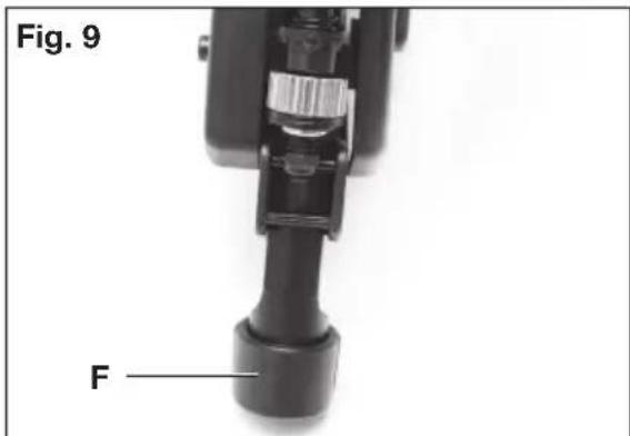
NO-MAR PAD (FIG. 9, 10)
⚠ WARNING: Disconnect tool from air supply and engage trigger lock, before removing or re-installing no-mar pad.
natural_image
Top-down view of a black mechanical component with labeled point A and arrow indicator (no text or symbols beyond labels)The no-mar pad (F) is provided to reduce marring of the work surface. The no-mar pad can be removed, and stored inside the End Cap, Magazine (M), to provide increased depth-of-drive for toe-nailing applications.
text_image
Fig. 9 F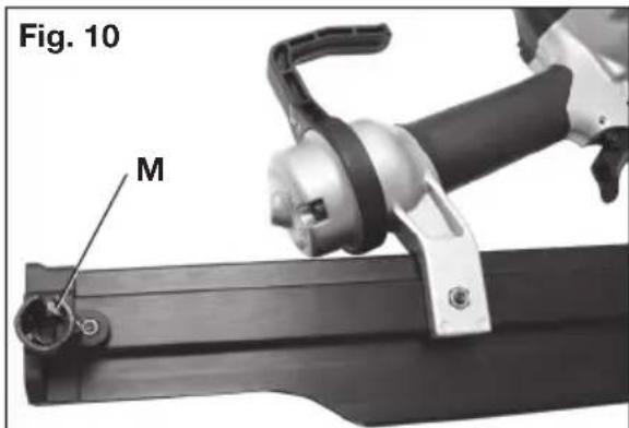
text_image
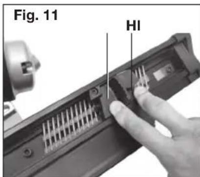
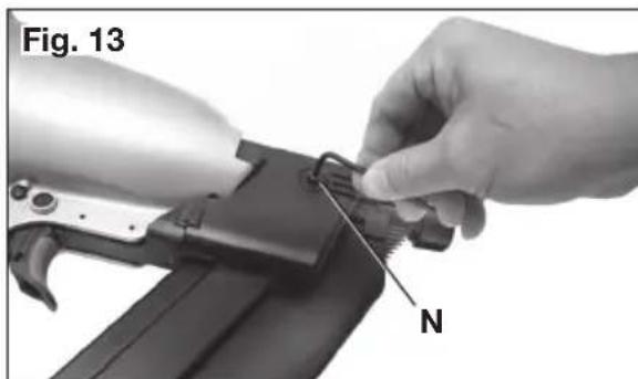
Fig. 10 MCLEARING A JAMMED NAIL (FIG. 1, 11–13)
WARNING: Disconnect air line from tool, engage trigger lock and relax fasteners from magazine before making adjustments or personal injury result.
If a nail becomes jammed in the nosepiece, keep the tool pointed away from you and follow these instructions to clear:
- Disconnect the air supply from the tool and engage trigger lock.
-
Depress pusher release (H) and slide pusher (I) all the way to the front of the magazine.
-
Depress nail stop (E) and slide fasteners from magazine.
text_image
Fig. 11 HI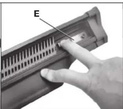
natural_image
Close-up of a hand inserting a component into a plastic housing with a labeled arrow (E), no visible text or symbols beyond the label.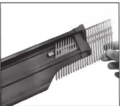
natural_image
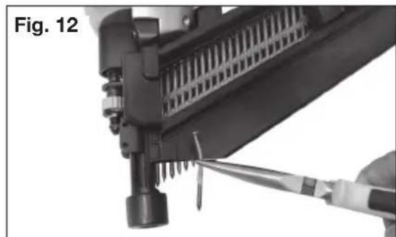
Close-up of a hand holding a black handheld device with metal pins inserted (no visible text or symbols)- If nail is jammed between the driver and nose casting force driver blade back to the top using a 1/4" (6.4 mm) punch and hammer. When the nail is released it will fall free or can be removed using pliers.
natural_image
Close-up of a mechanical component being adjusted with a screwdriver, labeled 'Fig. 12' (no other text or symbols visible)- If nail still can not be removed, remove the magazine:
a. Remove screws (N).
b. Remove magazine.
c. Remove bent nail.
d. Reassemble in reverse order.
NOTE: Should nails continue to jam frequently in nosepiece, have tool serviced by an authorized PORTER-CABLE service
natural_image
Close-up of hands using a tool to adjust or install a component, labeled 'N' (no text or symbols on the object itself)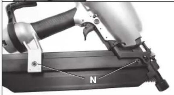
natural_image
Close-up of a mechanical assembly with labeled component 'N' (no readable text or symbols beyond label)When operating tools at temperatures below freezing:
- Make sure compressor tanks have been properly drained prior to use.
- Keep tool as warm as possible prior to use.
- Make certain all fasteners have been removed from magazine.
- Put 5 to 7 drops of PORTER-CABLE pneumatic tool oil in the air inlet.
- Lower air pressure to 80 psi (5.5 bar) or less.
- Reconnect air and load nails into magazine.
- Actuate the tool 5 or 6 times into scrap lumber to lubricate O-rings.
- Turn pressure up to operating level (not to exceed 120 psi) and use tool as normal.
- Re-lubricate at least once daily.
- Always drain the compressor tanks at least once a day.
Tool should operate normally. However, keep tool out of direct sunlight as excessive heat can deteriorate bumpers, O-rings and other rubber parts resulting in increased maintenance.
MAINTENANCE
WARNING: Disconnect air line from tool, engage trigger lock and rest fasteners from magazine before making adjustments or personal injury result.
| ACTION WHY HOW | ||
| Lubricate tool with 5-7 drops of PORTER-CABLE Pneumatic Tool Oil | Prevents failure of o-rings | Insert drops into air fitting on end cap of tool |
| Drain compressor tanks and hoses daily | Prevents accumulation of moisture in compressor and nailer | Open petcocks or other drain valves on compressor tanks. Allow any accumulated water to drain from hoses |
| Clean magazine, magazine release and contact trip mechanism. | Permits smooth operation of magazine, reduces wear and prevents jams. | Blow clean with compressor air. The use of oils, lubricants periodically or solvents is not recommended as they tend to attract debris. |
| Before each use, check to insure all screws, nuts and fasteners are tight and undamaged. | Prevents jams, leaks and premature failure of tool parts. | Tighten loose screws or other fasteners using the appropriate hex wrench or screwdriver. |
CLEANING
WARNING:
Never use solvents or other harsh chemicals for cleaning the non-
metallic parts of the tool. These chemicals may weaken the materials used in these parts. Use a cloth dampened only with water and mild soap. Never let any liquid get inside the tool; never immerse any part of the tool into a liquid.
REPAIRS
For assistance with your tool, visit our website at www.portercable.com for a list of service centers, or call the PORTER-CABLE Customer Care Center at 1-888-848-5175 (U.S. & Canada Only).
SERVICE
REPLACEMENT PARTS
Use only identical replacement parts. For a parts list or to order parts, visit our service website at http://servicenet.deltaportercable.com/. You can also order parts from your nearest PORTER-CABLE Factory Service Center or PORTER-CABLE Authorized Warranty Service Center. Or, you can call our Customer Care Center at 1-888-848-5175 (U.S. & Canada Only).
SERVICE AND REPAIRS
All quality tools will eventually require servicing and/or replacement of parts. For information about PORTER-CABLE, its factory service centers or authorized warranty service centers, visit our website at www.portercable.com or call our Customer Care Center at 1-888-848-5175 (U.S. & Canada Only). All repairs made by our service centers
are fully guaranteed against defective material and workmanship. We cannot guarantee repairs made or attempted by others.
You can also write to us for information at PORTER-CABLE, 4825 Highway 45 North, Jackson, Tennessee 38305 - Attention: Product Service. Be sure to include all of the information shown on the nameplate of your tool (model number, type, serial number, etc.).
ACCESSORIES
WARNING:
Since accessories, other than those offered by PORTER-CABLE, have not been tested with this product, use of such accessories with this tool could be hazardous. To reduce the risk of injury, only PORTER-CABLE recommended accessories should be used with this product.
A complete line of accessories is available from your PORTER-CABLE Factory Service Center or a PORTER-CABLE Authorized Warranty Service Center. Please visit our Web Site www.portercable.com for a catalog or for the name of your nearest supplier.
THREE YEAR LIMITED WARRANTY
PORTER-CABLE will repair, without charge, any defects due to faulty materials or workmanship for three years from the date of purchase. This warranty does not cover part failure due to normal wear or tool abuse. For further detail of warranty coverage and warranty repair information, visit www.portercable.com or call 1-888-848-5175 (U.S. & Canada Only). This warranty does not apply to accessories or damage caused where repairs have been made or attempted by others. This warranty gives you specific legal rights and you may have other rights which vary in certain states or provinces.
In addition to the warranty, PORTER-CABLE tools are covered by our:
1 YEAR FREE SERVICE: PORTER-CABLE will maintain the tool and replace worn parts caused by normal use, for free, any time during the first year after purchase.
90 DAY MONEY BACK GUARANTEE: If you are not completely satisfied with the performance of your PORTER-CABLE Power Tool, Laser, or Nailer for any reason, you can return it within 90 days from the date of purchase with a receipt for a full refund – no questions asked.
LATIN AMERICA: This warranty does not apply to products sold in Latin America. For products sold in Latin America, see country specific warranty information contained in the packaging, call the local company or see website for warranty information.
To register your tool for warranty service visit our website at www.portercable.com.
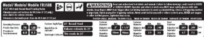
WARNING LABEL REPLACEMENT
If your warning labels become illegible or are missing, call 1-888-848-5175 (U.S. & Canada Only) for a free replacement.
text_image
Model/ Modelo/ Modèle FR350B 1 1/2 (40.5 mm) Record Head Framing Ruler Chandra de extraturation de 86.8 mm (2 1/2 px) para plante de subdura relonde Chandra à chargée pour clays de 86.8 mm (2 1/2 px) WARNING: Record and uncontrolled tool heads and edges. Failure to follow warning could result in 2020 and Record and uncontrolled tool heads and edges. Failure to follow warning could result in 2020 chields, keep triggers #REF from trigger when not driving triggers to avoid accidental bring. Choice of triggering method is important. Check manualizing triggering options. Never hold load at peak or others in work area. No other possible options are required or either locked glass, Explorant may occur. PROTECH NAME: JACQUEL, IN CHILLI-2A, MADE DE MACHIN DE LAURA PAROTÉ DE LAURA ANTICULTURA Operating Pressure W.P. M.P. Pressure Operative 70 120 P/S Pressure de Fordernement 4.6 8.3 mm Functional Angle Type 21° Record Head Functional Angle Type: 21° Record Head Functional Angle Type: 2° 31/2° Functional Angle Type: 30mm 50mm Functional Angle Type: 2.9 3.8 Functional Angle Type: 30mm 50mm Functional Angle Type: 30mm 50mm Functional Angle Type: 30mm 50mm Functional Angle Type: 30mm 50mm Functional Angle Type: 30mm 50mm Functional Angle Type: 30mm 50mm Functional Angle Type: 30mm 50mm Functional Angle Type: 30mm 50mm Functional Angle Type: 30cm 50cm Functional Angle Type: 30cm 50cm Functional Angle Type: 30cm 50cm Functional Angle Type: 30cm 50cm Functional Angle Type: 30cm 50cm Functional Angle Type: 30cm 50cm Functional Angle Type: 30cm 50cm Functional Angle Type: 30cm 50cm Functional Angle Type: 30m 50m Functional Angle Type: 30m 50m Functional Angle Type: 30m 50m Functional Angle Type: 30m 50m Functional Angle Type: 30m 50m Functional Angle Type: 30m 50m Functional Angle Type: 30m 50m Functional Angle Type: 30m 50m Functional Angle Type: 30cm 50cm Functional Angle Type: 30cm 50cm Functional Angle Type: 30cm 50cm Functional Angle Type: 30cm 50cm Functional Angle Type: 30cm 50cm Functional Angle Type: 30cm 50cm Functional Angle Type: 30cm 50cm Functional Angle Type: 30c m 50c m Functional Angle Type: 30c m 50c m Functional Angle Type: 30c m 50c m Functional Angle Type: 30c m 50c m Functional Angle Type: 30c m 50c m Functional Angle Type: 30c m 50c m Functional Angle Type: 30c m 50c m Functional Angle Type: 30c cm 50cm Functional Angle Type: 30c cm 50cm Functional Angle Type: 30c cm 50cm Functional Angle Type: 30c cm 50cm Functional Angle Type: 30c cm 50cm Functional Angle Type: 30c cm 50cm
| TROUBLESHOOTING GUIDE | ||
| MANY COMMON PROBLEMS CAN BE SOLVED EASILY BY UTILIZING THE CHART BELOW. FOR MORE SERIOUS OR PERSISTENT PROBLEMS, CONTACT A PORTER-CABLE SERVICE CENTER OR CALL 1 888 848-5175.⚠ WARNING: To reduce the risk of serious personal injury, ALWAYS disconnect air from tool and engage trigger lock, before all repairs. | ||
| SYMPTOM PROBLEMS SOLUTIONS | ||
| Air leak near top of tool or in trigger area | Loose screws. Tighten screws. | |
| Worn or damaged o-rings or seals. | Install Overhaul Kit. | |
| Tool does nothing or operates sluggishly | Inadequate air supply. Verify adequate air supply. | |
| Inadequate lubrication. Put 5 or 7 drops of oil into air inlet. | ||
| Worn or damaged o-rings or seals. | Install Overhaul Kit. | |
| Air leak near bottom of tool | Loose screws. Tighten screws. | |
| Worn or damaged o-rings or bumper. | Install Overhaul Kit. | |
| Tool jams frequently Incorrect fasteners. Verify approved fasteners of correct size and 22° collation angle. | ||
| Other Contact a PORTER-CABLE | Authorized Warranty Service Center | |
| TOOL SPECIFICATIONS | |
| FR350B | |
| Height (inch/mm) | 14.76/375 |
| Width (inch/mm) | 4.72/120 |
| Length (inch/mm) | 21.65/550 |
| Weight (lbs/kg) | 7.17/3.25 |
| Recommended Operating Pressure | 70-120 psi (4.8 to 8.3 bar) |
| Air Consumption per 100 cycles | 9.74 CFM |
| Loading capacity | 60 nails |
| Compressor will be sufficient for tools at all production rates. | |
| Compressor will be sufficient at slow or moderate production rates, but may have difficulty at very rapid rates. | |
| Compressor will be adequate only when tools are utilized at slow production rates (punch-out or occasional use). | |
| NR | Not Recommended |
| Portable Handcarry3.2 – 4 CFM | 5.5 HP Gas2 HP Elec.8 – 9 CFM | 8 HP Gas14 – 16 CFM | Industrial23+ CFM | ||
 |  |  | [ZCYS] | ||
| NUMBER OF TOCOMPRESSOR | 1 | ||||
| 2 | |||||
| 3 | |||||
| 4 | NR | ||||
| 5 | NR | ||||
| 6 | NRNR | ||||
| 7 | NRNR | ||||
| 8+ | NRNR | ||||
CONSIGNES DE SÉCURITÉ IMPORTANTES A POUR LES OUTILS PNEUMATIQUES
CONSERVEZ CES DIRECTIVES
natural_image
Diagram of a pressure regulator with two gauges and two side fans (no text or labels)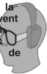

natural_image
Illustration of a coiled cable or hose with a handle (no text or symbols)comme Fig. E

natural_image
Illustration of a hand operating a NI95 electric drill press machine with a tool, no text or symbols present
natural_image
Illustration of a hand using a power tool to clean or repair a wooden object, no text or symbols presentLes
text_image
Diagram illustrating a pressure gauge over a geological or hydrological feature with directional arrows and layered structure.text_image
A B C PORTER CABLE J K D E G F H IASSEMBLAGE
text_image
Fig. 2 D J L K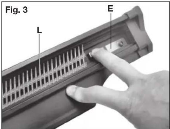
text_image
Fig. 3 L E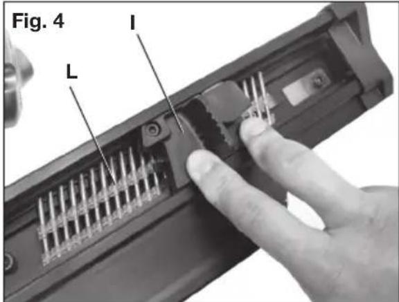
text_image
Fig. 4 I Lnatural_image
Close-up of a mechanical component with labeled section A, showing internal structure and mounting holes (no text or symbols beyond labels)APPUI ANTIMARQUES (FIG. 9, 10)
DÉGAGEMENT DES CLOUS COINCÉS (FIG. 1, 11-13)
natural_image
Close-up of a mechanical tool with a screwdriver inserted, labeled 'Fig. 12' (no other text or symbols visible)natural_image
Close-up of a precision airknaver with labeled component 'N' (no text or symbols beyond label)text_image
Model/ Modelo/ Modèle FR350B 1.12 (19.5 mm) Rearl head Fracing Washer Chandraza para extractions de 18.8 mm (2.15 psi) para flares de sabaire meloneta Chandraza a chargeable per pair de 36.8 mm (2.17 psi) WARNING: Brand and understandable labels and manual features to follow warnings could result in 36.8 mm (2018) SABAR, Expeller and others in work area (MUS) over using glasses with slice size, deep fingers (DAR) from finger when not driving frontiers to avoid accidental bring. Choice is triggering method is important. Check manufacturer's warning options. Made until bed at passed or either in work area, MUS are suggestive or other bottled glasses, Expeller may occur. PERFORMER: JACQUEEN, IN CHINA'S, MADE IN CHINA'S FOR TAWAN, MADE IN CHINA'S FOR TAWAN, KITCHEN'S Board Pressure: M.P. Pressure Operator: 70 Pressure Factor: 4.8 Performance Rate: 9.3 Fastener Angle/Type: 21° Rcvnd Head Laparial Type of Nextelator: 21° Cobuzia redentra de 21° Tire range de 21° Fastener Diameter: 2" 3.1/2" Standard Error: 1.13 Standard Deviation: 1.48 Standard Size: 2.9 Standard Position: 3.0 Standard Side: 6.7 Standard Side: 7.5
text_image
ADVERTENCIA Lea y comprenda las éliguetas y el manual de la herramienta. No seguir las instrucciones podría provocar la MUERTE o LESIONES GRAVES. En UBILATORIO que el operador y las demás personas que están en el área de trabajo utilien gales de seguridad con protecciones laterales. Mantenga les deden ALEJANDOS del gallo cuando no este colocando sujeladores para evitar que la herramienta se dispare accidentamente. La election del método de disparo es importante. Lea el manual para conocer las opciones de disparo. MUNCA apurite la herramienta hacia usted o hacia otras personas que están en el área de trabajo. MUNCA utilio oxigento o otros gases enzadas. Esta podría provocar una expresión. AVERTISSEMENT Live et comprendre los éliguetes apposées sur l'aviti et dans le manuel. Ho pas respecter las avrisslements peut provequer la MORT ou des BLEISSURES GRAVES. L'opérateur et les autres personnes présentes dans la zona de travail DIIVENT porter des lattentes de sécurité avec coques latricales, ELONIER les droits de la glechte a la fit de la pose des attaches pour éviter un tir accidente! Le choix la mode de déclenchement est important. Construer le manuel pour comatralles les options de déclenchement. NE JAMAIS pour haudt vers une vue les personnes présentes dans la zone de travail. NE JAMAIS utilise d'oxygène ou d'autres gaz en bouille. Une expression peut surveir.GUIDE DE DÉPANNAGE
IL EST POSSIBLE DE RÉSOUDRE FACILEMENT LES PROBLÈMES LES PLUS COMMUNS À L'AIDE DU TABLEAU CI-DESSOUS. DANS LE CAS DE PROBLÈMES GRAVES OU PERSISTANTS, CONTACTER UN CENTRE DE RÉPARATION PORTER-CABLE OU COMPOSER LE 1 888 848-5175.
⚠ AVERTISSEMENT :
natural_image
Illustration of a coiled hose with a plug, no text or symbols presenttext_image
A B C J K D E G F H IENSAMBLAJE
text_image
Fig. 2 D J L K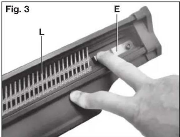
text_image
Fig. 3 L E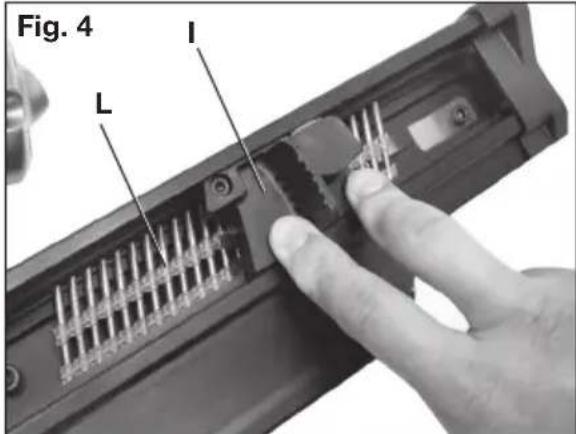
text_image
Fig. 4 I Lnatural_image
Close-up of a mechanical device with a metallic gear and adjustment knob (no visible text or symbols)natural_image
Close-up of a black mechanical component with labeled point A and arrow indicator (no text or symbols beyond labels)ALMOHADILLA NO-MAR (FIG. 9, 10)
natural_image
Close-up of a hand inserting a component into a device (no visible text or symbols)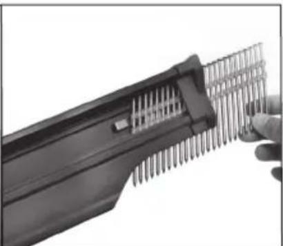
natural_image
Close-up of a hand holding a handheld electronic device with metallic pins (no visible text or symbols)