ZISTE6700DH - Generator Zipper - Free user manual and instructions
Find the device manual for free ZISTE6700DH Zipper in PDF.

| Brand | Zipper |
| Model | ZISTE6700DH |
| Product type | Diesel generator |
| Engine | Diesel 4-stroke, air-cooled |
| Fuel | Diesel EN 590 |
| Starting | Electric (key) and manual (recoil start) |
| Output voltage | 230 V AC (single-phase) |
| 12 V DC output | Up to 8.3 A |
| Voltage regulator | AVR (automatic voltage regulation) |
| Protection | Protection circuit breaker |
| Recommended engine oil | SAE 15W-40, classification CF/CH-4/CI-4 |
| Oil level | Check before each start, engine will not start if low level |
| Air filter | Clean regularly, replace if necessary |
| Oil change | Every 100 hours or 3 months |
| Safety | Automatic low oil shutdown, overload protection |
| Usage | Outdoor only, avoid moisture and rain |
| Operating temperature | +5 °C to +40 °C |
| Max altitude | 1800 m |
| Spare parts | Available via Zipper catalog |
| Warranty | 2 years non-commercial use, 1 year commercial |
Frequently Asked Questions - ZISTE6700DH Zipper
User questions about ZISTE6700DH Zipper
0 question about this device. Answer the ones you know or ask your own.
Ask a new question about this device
Download the instructions for your Generator in PDF format for free! Find your manual ZISTE6700DH - Zipper and take your electronic device back in hand. On this page are published all the documents necessary for the use of your device. ZISTE6700DH by Zipper.
USER MANUAL ZISTE6700DH Zipper
EN USER MANUAL GENERATOR
SL NAVODILO ZA UPORABO
GENERATOR
FR MODE D'EMPLOI GROUPE ÉLECTROGÈNE
natural_image
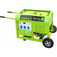
Green ZIPPER ZI-STE6700DH portable electricity generator with visible components and wheels (no text or symbols on body)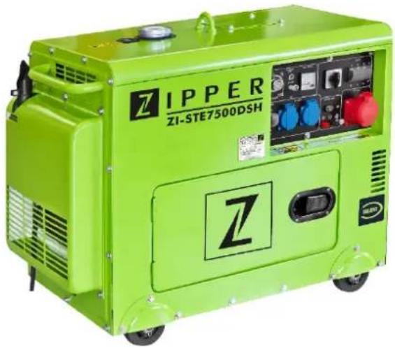
natural_image
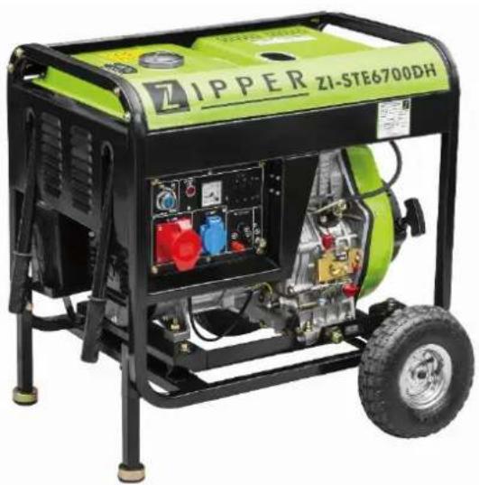
Green ZIPPER industrial machine with control panel and buttons (no visible text or symbols on body)ZI-STE6700DH
EAN : 9120039233499
ZI-STE7500DSH
EAN : 9120039233505
CE
Engine doen't start with low oil!
11.1 Intended use of the machine.... 21
11.1.1 Technical Restrictions 21
11.1.2 Prohibited Use / Forseeable Misuse....21
11.2 User Requirements.... 21
11.3 Safety instructions 22
11.4 Special safety instructions for the operation of the machine.... 22
11.5 Safety instructions for machines with combustion engine.... 22
11.6 Hazard warnings 22
12 ASSEMBLY 23
12.1 Check scope of delivery 23
13 OPERATION 24
13.1 Checklist before each use.... 24
13.1.1 Checking the engine oil level 24
13.1.2 Checking the fuel tank level....25
13.1.3 Check the air filter....25
13.1.4 Grounding....25
13.2 First use 26
13.3 Operation 26
13.3.1 Starting the engine: 26
13.3.2 Stop the engine 26
13.3.3 Electrical consumers....26
14 MAINTENANCE 27
14.1.1 Engine oil change....27
14.1.2 Transport / Storage....28
14.2 Disposal.... 28
15 TROUBLESHOOTING 28
16 UVOD (SL) 29
17 VARNOST 30
17.1 Namenska uporaba.... 30
EN CE-Conformal! - This product complies with the EC-directives.
EN Follow the instructions!
EN No open flame, fire, open source of ignition and smoking prohibited!
EN Danger of Intoxication (CO)! Only use outdoors and far from open windows and vents!
EN Keep safe distance!
EN Protect from moisture!
EN Warning of flammable liquids; turn off the engine before filling (gasoline)
EN ATTENTION: Check Oil! Engine don't start with low oil!!
natural_image
Green industrial machine labeled 'ZIPPER' with control panel and 'Z' marking (no readable text beyond branding)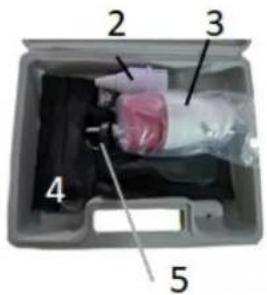
text_image
2 3 4 56+7

natural_image
Exterior view of a green ZIPPER ZI-ST6700DH industrial machine (no visible text or symbols on body)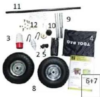
text_image
11 12 10 9 3 2 5 8 6+7 TOOL M40ZI-STE7500DSH
| 1 | Generator / Générateur |
| 2 | Stecker / Plug / Vtič 230V / Prise |
| 3 | Stecker / Plug / Vtič 400V / Prise |
| 4 | Werkzeug / Tools / Orodje (Box) / Outil |
| 5 | Start-Schlüssel / start key / Vklopni ključ / Clé de démarrage |
| 6 | Motormanual / Engine manual / Ročni motor / Manuel du moteur |
| 7 | Bedienungsanleitung / manual / Navodilo za uporabo / Mode d'emploi |
ZI-STE6700DH
| 1 | Generator / Générateur |
| 2 | Stecker / Plug / Vtič 230V / Prise |
| 3 | Stecker / Plug / Vtič 400V / Prise |
| 4 | Werkzeug / Tools / Orodje (Box) / Outil |
| 5 | Start-Schlüssel / start key / Vklopni ključ / Clé de démarrage |
| 6 | Motormanual / Engine manual / Ročni motor / Manuel du moteur |
| 7 | Bedienungsanleitung / manual / Navodilo za uporabo / Mode d'emploi |
| 8 | Räder / wheels / Kolesa / Roues |
| 9 | Fußestreben / foot rods / palice za noge / Montants de pied |
| 10 | Gummifüße / rubber feet / gumijaste noge / Pieds en caoutchouc |
| 11 | Achse / axes / osi / Axe |
4 VORWORT (DE)
natural_image
Mechanical assembly diagram showing a vehicle's internal components with a highlighted section (no text or symbols visible)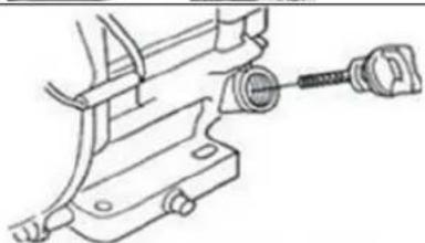
natural_image
Technical line drawing of a mechanical clamp or bracket assembly (no text or symbols)
text_image
Obergrenze UntergrenzeThis manual contains information and important instructions for the installation and correct use of the ZIPPER generators ZI-STE6700DH and ZI-STE7500DSH.
Following the usual commercial name of the machine (see cover) is substituted in this manual with the name "machine".

This manual is part of the product and shall not be stored separately from the product. Save it for later reference and if you let other people use the product, add this instruction manual to the product.
Please read and obey the security instructions!
Due to constant advancements in product design, construction pictures and content may diverse slightly. However, if you discover any errors, inform us please.
Technical specifications are subject to changes!
Please check the product contents immediately after receipt for any eventual transport damage or missing parts.
Claims from transport damage or missing parts must be placed immediately after initial product receipt and unpacking before putting the product into operation.
Please understand that later claims cannot be accepted anymore.
Copyright
© 2018
This document is protected by international copyright law. Any unauthorized duplication, translation or use of pictures, illustrations or text of this manual will be pursued by law.
Court of jurisdiction is the regional court Linz or the competent court for 4707 Schlüsslberg, Austria!
Customer service contact
This section contains information and important notices for safe commissioning and handling of machine.

For your own safety, read these operating instructions carefully before putting the machine into operation. This will enable you to handle the machine safely and prevent misunderstandings as well as possible damage to property and persons. Also observe the symbols and pictograms used as well as the safety instructions and hazard warnings!
11.1 Intended use of the machine
The machine is intended exclusively for the following activities:
This power unit is designed exclusively for operating electric devices whose max. performance is within the specifications for the generator. A higher starting current of inductive loads must be considered. The generator is designed to operate from conventional resistive and inductive loads, such as Lights, electric hand tools (drills, electric chain saws, compressors) determined.
When connecting to stationary systems such as heating, house supply, air conditioning or for the power supply of mobile homes, an electrician and the heating manufacturer must be consulted regarding the connection and grounding.
ZIPPER-MASCHINEN assumes no responsibility or warranty for any other use or use beyond this and for any resulting damage to property or injury.
11.1.1 Technical Restrictions
The machine is intended for use under the following ambient conditions:
Relative humidity: max. 65 %
Temperature (for operation) +5°C bis +40°C
Temperature (for storage and/or transport) -20°C bis +55°C
11.1.2 Prohibited Use / Forseeable Misuse
• Operation of the machine without adequate physical and mental aptitude
- Operating the machine without appropriate knowledge of the operating instructions (machine + motor).
• Changes in the design of the machine
• Operating the machine in wet and rainy conditions
• Operating the machine in a potentially explosive environment
• Operating the machine indoors or in closed areas
• Operation of the machine without functioning or missing guards
- Remove the safety markings attached to the machine.
- Modify, circumvent or disable the safety devices of the machine.
The prohibited/hazardous use or disregard of the information and instructions presented in this manual will result in the voiding of all warranty and damage claims against Zipper Maschinen GmbH.
11.2 User Requirements
The physical and mental suitability as well as knowledge and understanding of the operating instructions are prerequisites for operating the machine. Persons who, because of their physical, sensory or mental abilities or their inexperience or ignorance, are unable to operate the machinery safely must not use it without the supervision or instruction by a responsible person.
Please note that local laws and regulations may determine the minimum age of the operator and restrict the use of this machine!
Put on your personal protective equipment before working on the machine.
Work on electrical components or equipment may only be carried out by a qualified electrician or carried out under the guidance and supervision of a qualified Electrician.
11.3 Safety instructions
In order to avoid malfunctions, damage and health hazards when working with this machine, in addition to the general rules for safe working, the following measures in particular must be observed UNCONDITIONALLY:
- Check that the machine is in perfect condition before each use. Ensure that all guards are in place and working properly and that all nuts, bolts, etc. are securely tightened. Do not take the machine into operation if you notice that parts are missing or damaged!
- Ensure sufficient lighting conditions in the working and surrounding areas of the machine.
- Keep hands and feet away from moving machine parts and always ensure a safe stand when working.
- Ensure that the area to be tamped does not contain any electric cables, gas or water lines which could be damaged by vibration.
- Remove the adjustment tool from the machine before operation.
- Ensure that unauthorised persons maintain a safe distance from the machine and keep children away from the machine.
- The machine may only be operated, serviced or repaired by persons who are familiar with it and who have been informed of the dangers arising during this work.
- Always wear suitable personal protective equipment (eq. ear protection,..., etc.)!
- Do not work with the machine if you are tired, not concentrated or under the influence of medication, alcohol or drugs!
- Never operate the unit in the presence of flammable liquids or gases (danger of explosion!).
- Carry out maintenance, adjustment and cleaning work only when the engine is switched off.
- Only use spare parts and accessories recommended by Zipper machines.
11.4 Special safety instructions for the operation of the machine
- Do not use the generator if it is raining, wet or has high humidity. RISK OF ELECTRIC SHOCK. DANGER OF LIFE!.
11.5 Safety instructions for machines with combustion engine
- Do not touch the engine and/or muffler during operation or immediately after switching off! These areas become hot during operation and can cause burns.
- Do not touch the spark plug connector when the engine is running (electric shock!).
- Do not operate the unit in closed areas or in poorly ventilated rooms unless there is adequate ventilation through exhaust fans or hoses. (Risk of suffocation from carbon monoxide!)
- Do not smoke while the machine is in operation.
- Do not smoke when refuelling the machine.
• Refuel the machine only in a well ventilated area. - Do not refuel the machine when the engine is running or the machine is still hot.
- Do not refuel the machine near naked flames.
- Do not spill fuel when refuelling.
- Do not crank a gas flooded engine as long as the spark plug is removed- fuel in the cylinder sprays out of the spark plug opening.
- Do not carry out an ignition spark test on engines if the engine is flooded or gas can be smelled. A stray spark could ignite the vapours.
- Do not use fuel to clean machine parts, especially indoors. Vapours from fuels may explode.
- Always keep the area around the muffler free of foreign substances such as leaves, paper, cardboard, etc. A hot muffler could ignite these substances and cause a fire.
- Close the filler cap after refuelling.
- Check the fuel line and tank regularly for leaks and cracks. Do not operate the machine if leaks in the fuel system are known.
- Store fuel only in designated and approved containers.
11.6 Hazard warnings
Despite intended use, certain residual risks remain.
- Risk of burns:
Touching the mufflers, exhaust and other machine components which can be hot after prolonged continuous operation or when the engine is hot cause severe burns.
• Risk of fire and explosion:
NEVER refuel fuel or engine oil while the machine is in operation or is hot.
When refuelling and at places where fuel is stored not smoke or allow open flames or sparks.
Do not overfill the fuel tank and avoid the spillage of gasoline during refuelling. If fuel is spilled, make sure the area is completely dry and cleaned before starting the engine.
Make sure that the filler cap is tightly closed again after refuelling safely.
- Chemical risks
Never use or refuel a gasoline or diesel engine in a closed area without adequate ventilation. Carbon monoxide emissions from the internal drive units of the engine can cause in confined spaces through inhalation health effects and death. Therefore, use the machine only in well-ventilated rooms or outdoors in operation.
Liquid fuels can cause serious damage on the skin and the environment.
- Risk of electric shock
Direct electrical contact may cause electric shock.
Never touch the unit with wet hands. Provide adequate grounding.
- Hearing damage
A longer stay in the immediate vicinity of the running unit may cause hearing damage.
Wear ear protectors!
Due to the design and construction of the machine, hazardous situations may occur which are identified as follows in these operating instructions:
DANGER

A safety instruction designed in this way indicates an imminently hazardous situation which, if not avoided, will result in death or serious injury.
WARNING

Such a safety instruction indicates a potentially hazardous situation which, if not avoided, may result in serious injury or even death.
CAUTION

A safety instruction designed in this way indicates a potentially hazardous situation which, if not avoided, may result in minor or moderate injury.
NOTICE

A safety note designed in this way indicates a potentially dangerous situation which, if not avoided, may result in property damage.
Irrespective of all safety regulations, their sound common sense and corresponding technical suitability/training are and remain the most important safety factor in the error-free operation of the machine. Safe working depends first and foremost on you!
12 ASSEMBLY
12.1 Check scope of delivery
After delivery, check the machine immediately for transport damage and missing Parts.
ZI-STE6700DH:
The machine is delivered almost fully assembled. If desired, the transport unit can be mounted and battery have to be connected.
 | Assembly wheel shaftFix the wheel shaft to the frame with 2 clamps and 4 screws. | |
 | Assembly wheelsPlace the wheel (1) on the stub shaft (3), add washers (4) and secure against axial movement by means of the cotter pin (3). Carry out that assembly steps on both sides. | |
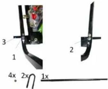
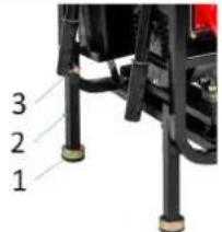 | Assembly FeetAttach the rubber feet (1) to the stand feet (29) and slide the stand foot (2) into the holder on the frame and secure it with the screw (3). | |
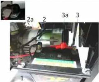 | Connecting the batteryThe battery is attached to the frame by means of a holding bracket (1) or can be removed after loosening.Clamp the (+) pole (3) red to the battery using a screw connection, then clamp the (-) pole (2) black to the battery using a screw connection. Put both pole covers (2a, 3a) back in place to protect the two poles. | |
ZI-STE7500DSH:
The machine is delivered fully assembled. There is no further assembly necessary, except connection of the battery.
13 OPERATION
This power unit is designed exclusively for operating electric devices whose max. Performance within the performance specifications of the generator. A higher starting current of inductive loads must be considered.
13.1 Checklist before each use
13.1.1 Checking the engine oil level
NOTICE

Too low an oil level will damage the engine and shorten the life of the machine. Therefore, check the engine oil level before every start and top up the engine oil if necessary.
NOTICE


Engine oil and fuels are toxic and must not be released into the environment! Follow the instructions of the supplier and, if necessary, contact your local authorities for information on proper disposal.
| 1. To check the engine oil level, place the machine on a safe, level surface. Switch off the engine and allow the machine to stand for ten minutes so that the circulating oil can collect in the oil pan.2. Unscrew the oil dipstick and wipe with a clean, lint-free cloth or a non-fibrous paper towel. | |
 | 3. Push the dipstick into the opening, but do not screw it in. (Make sure that the dipstick has really been pushed in completely). |
 | 4. Pull out the oil dipstick again and read off the oil level. There are two markings for this - see illustration on the left.5. If the oil level is low, refill the recommended oil up to the upper edge6. Push in the oil dipstick again and tighten. |
To operate the generator, use engine oil that meets the following requirements:
■ suitable for diesel engines
■ 0W30 or 15W40
■ with classification CF/ CH-4/ or CI-4
For year-round operation, engine oil with SAE viscosity level 15W-40 is recommended.
13.1.2 Checking the fuel tank level
NOTICE

Observe the safety regulations for fuel control. Filter the fuel during refuelling to prevent foreign particles from entering the combustion chamber. Wipe up leaked fuel.
- Screw on the tank cap (sits on the fuel tank).
- Level check in the form of a visual inspection or via display. If necessary, top up with diesel fuel with the appropriate standard EN 590.
- Close the fuel filler cap tightly after refuelling.
13.1.3 Check the air filter
Check the core of the air filter, ensuring that it is clean and performs well.
- Loosen the screw on the cover of the filter, and then dismantle the cover to check the filter.
- Please clean or change the filter if necessary.
NOTICE

- Do not run the engine without the air filter, or else filth will enter the engine through carburetor, resulting in quick wear and tear of the engine.
- If the power output drops or the colour of the exhaust gases does not lock normal, renew the air filter immediately.
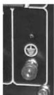
13.1.4 Grounding
Before starting up the machine, have it grounded by a qualified electrician! If the machine is intended for mobile operation, get a grounding cable with sufficient cross section from your electrical retailer.
13.2 First use
Make sure to treat the machine with care, when using it for the first time. After starting, let the motor run for 5 minutes without connecting the generator with consumer load.
Following points should be checked in the first 5 minutes:
• Is the sound of the generator normal?
• Are the vibrations not to strong?
• Exhaust gases should not look black or white.
• Is oil pilot light showing?
If these points meet the demands, the generator can be used further. Otherwise stop the generator and find the cause of the problem.
13.3 Operation
13.3.1 Starting the engine:
- Open fuel tap.
- Set the speed control to position „RUN“.
- Electronic starter:
- Set ignition key to position "ON". After waiting 1-2 seconds, turn the ignition key to position "Start".
- Release ignition key as soon as the engine has started.
- If the engine does not start within ten seconds, stop the starting process.
- Wait at least 30 seconds, before attempting a new start.
- Recoil starter:
- Pull the rope hard and fast.
- Pull the rope all the way out.
- Use two hands if necessary
Possible reasons for starting difficulties:
- Cold weather – if necessary, use starter-spray in the intake nozzle.
- Low battery, low acidity level – contact a qualified person or, with appropriate experience, refill distilled water yourself.
■ Low oil (refill oil)
■ Air in fuel-pipeline.
13.3.2 Stop the engine
NOTICE

- Disconnect all electronic equipment from the generator before switching off the engine.
- Allow the device to continue running for approx. five minutes (5 min) after a long period of use. This helps the motor to cool down.
Turning off procedure
■ Set circuit breaker to position "OFF".
■ Turn ignition key to the left into position "OFF".
- Close fuel tap.
13.3.3 Electrical consumers
When the generator is running on nominal speed, electrical consumers can be connected. (Only for ZI-STE7500DSH: Select whether 230V or 400V should be operated by means of selector switch) Activate circuit breaker (ON;I))
When operating several consumers, you should first connect the consumer with the higher inrush currents requirement! If no problem occurs, more consumers can be connected. If the generator shuts down, the required power was probably too high.
NOTICE

Make sure, the max. power output of the generator is not exceeded.
If the voltage (see voltmeter) is too high or too low, adjust the speed level. If a problem occurs, stop the generator and take care of the problem.
At the DC-module (12V), a maximum amount of 8.3 A current is possible.
CAUTION

Pay attention to correct connecting: Red connection: + terminal Black connection: - terminal
14 MAINTENANCE
The machine is low-maintenance. It contains only a few parts, which have to be maintained regularly by the operator. Malfunctions or defects that could impair the safety of the machine must be repaired immediately.
WARNING

Hot surfaces and rotating machine parts while the engine is running can cause serious injury or even death. Always stop the machine before carrying out any conversion, adjustment, cleaning or maintenance work and secure it against unintentional restarting and wait until the machine has cooled down
Please maintain the generator in specified months or hours whatever comes first.
| Before any use | After 1. month or after first 20 operating hours | After 3 month or every 100 operating hours | After 6 month or every 500 operating hours | |
| Check tank, refuel if necessary | O | |||
| Check engine oil level, refill if necessary | O | |||
| Check for loss of fuel or oil | O | |||
| Check for loose or missing screws | O O | |||
| Changing of oil | (O) | O | ||
| Changing of fuel | (O) | |||
| Cleaning the air filter | O | |||
| Cleaning the fuel filter | O | |||
| Check fuel line, replace if necessary | O | |||
| Check battery | 1 x every month | |||
- If used in dirty places, the generator should be maintained more regularly.
- If the user does not have the right tool, or has too little knowledge, maintenance should be performed by a qualified person.
14.1.1 Engine oil change
NOTICE


Engine oil is toxic and must not be released into the environment! Follow the instructions of the supplier and, if necessary, contact your local authorities for information on proper disposal.
NOTICE

Changing the oil is easier when the engine is still warm.
- Remove the oil outlet screw.
- Drain the dirty oil into a suitable container.
• Fix the oil outlet screw again. - Fill in new engine oil
- Check the engine oil level with the dipstick
• If the level is correct reinsert the dipstick
14.1.2 Transport / Storage
In order to avoid the generator leaking oil during transport or temporary storage, make sure to switch off the generator, keeping it at a standing pose under normal operations. After the engine is totally cooled, turn the ventilating pole of the fuel-filling lid to the "OFF" position thoroughly.
When transporting the generator:
- Do not let the fuel spill out of the fuel tank. (The top of the fuel-filling tank should have no fuel.)
- When the generator is placed on a vehicle, do not run the engine. You should take the generator down from the car before operation.
- When you take the generator to the car, avoid exposing it to sunshine. If it is put in sealed carriage for a long time, the high temperature of the carriage may cause the fuel to boiling away, thus leads to burn.
Before the generator is put into a long-time storage, you should:
Make sure the storage area is clean and dry.
NOTICE

Store the machine with closed inlet- and outlet valves. Therefore, pull on the rope of the starter until you fell resistance.
14.2 Disposal
Do not dispose of the machine in residual waste. Contact your local authorities for information regarding the available disposal options. When you buy at your local dealer for a replacement unit, the latter is obliged to exchange your old.
15 TROUBLESHOOTING
WARNING

Hot surfaces and rotating machine parts while the engine is running can cause serious injury or even death. Always stop the machine before carrying out any conversion, adjustment, cleaning or maintenance work and secure it against unintentional restarting and wait until the machine has cooled down
If you find yourself unable to carry out necessary repairs properly and/or do not have the required training to do so, always consult a specialist to fix the problem.
| Trouble | Reason | Shooting |
| Engine will not start up | ·Fuel cock closed·No fuel·Too little oil in the tank·Air in fuel pipeline·Battery too weak | ·Set fuel cock in position "ON"·Refill fuel·Refill oil·Have the fuel pipeline blown through·Charge the battery with appropriate charger |
| Engine runs unevenly | ·Wrong fuel·Air in fuel pipeline | ·Use correct fuel·Have the fuel pipeline blown through |
| Motor too little power | ·Dirty air filter | ·Clean the filter elements, possibly exchange |
| Low output voltage under load | ·Too much load available | ·Reduce existing load |
| Uneven Output voltage | ·Unbalanced load available | ·Disconnect all electrical consumers. Then apply again individually to determine which consumer causes the uneven loads. |
| High noise level | ·Loose screw connections | ·Tighten all screws |
16 UVOD (SL)
Spoštovani kupec!
Cher client, chère cliente,
23.1.1 Restrictions techniques
natural_image
Mechanical assembly diagram showing a vehicle chassis with labeled components (no readable text or symbols)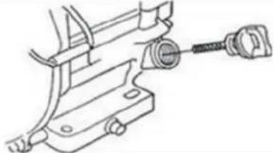
natural_image
Technical line drawing of a mechanical clamp or bracket assembly (no text or symbols)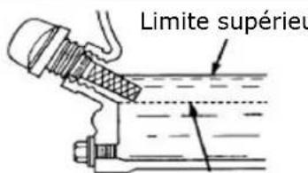
text_image
Electrical schematic diagram with labeled components including air vent, motor, and electrical meters29 EXPLOSIONSZEICHNUNGEN / EXPLODED DRAWINGS / RAZSTAVLJENA RISBA / VUES ÉCLATÉES
29.1 STE6700DH
text_image
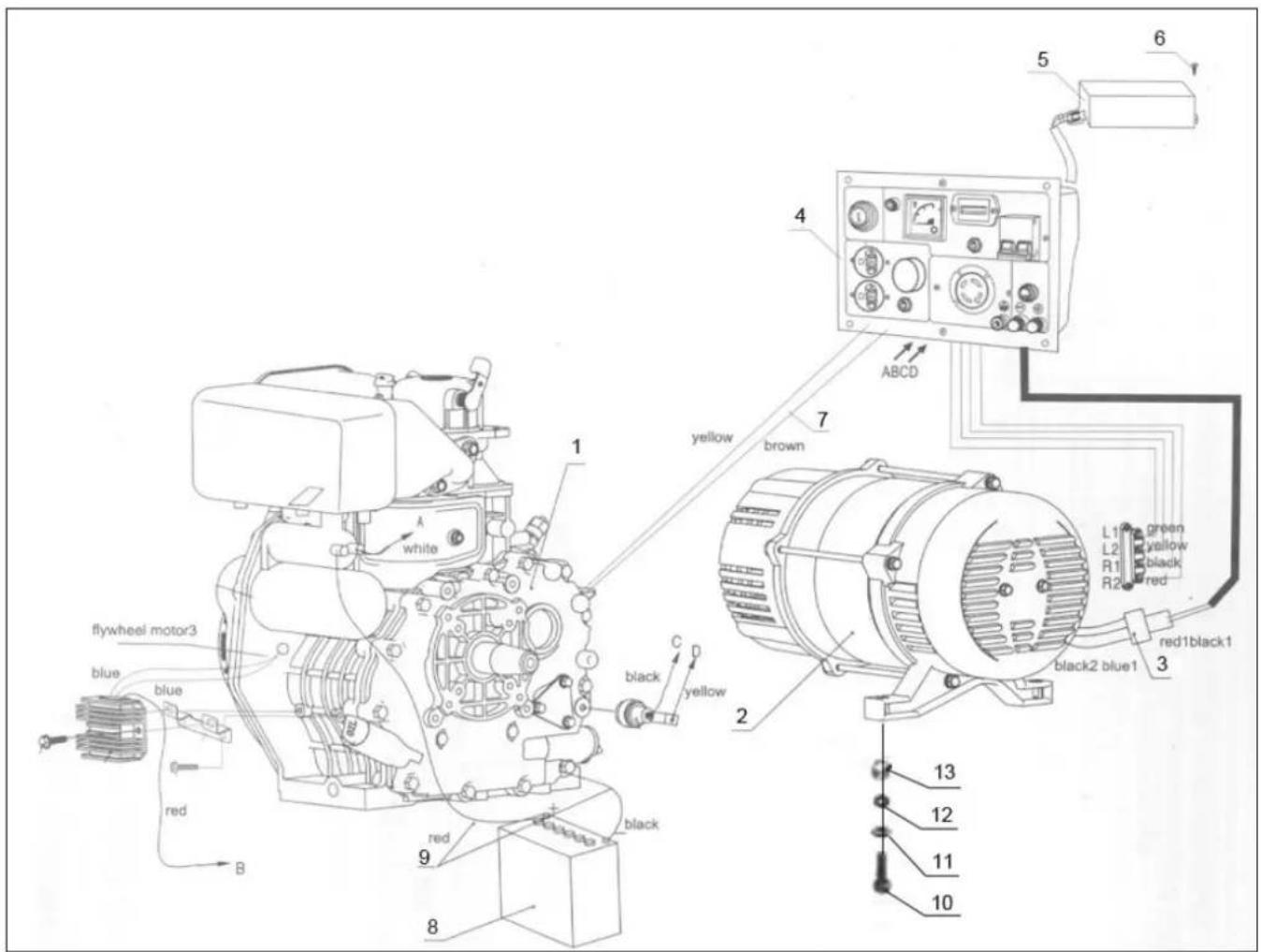
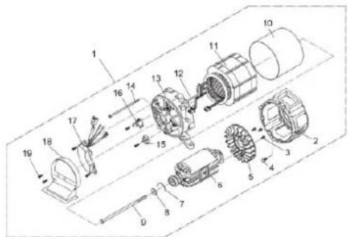
flywheel motor3 blue blue red B white 1 2 black yellow C D 8 9 red black 10 11 12 13 13 12 11 13 12 11 13 5 6 4 yellow brown ABCD 7 green yellow black red L1 L2 R1 R2 red1black1 black2 blue1 3Engine-Generator Assembly
| No | Description | No | Description |
| 1 | Diesel engine | 8 | Battery |
| 2 | Generator | 9 | Battery Cable |
| 3 | Connector assembly | 10 | Bolt M10x45 |
| 4 | Output panel assembly | 11 | Flat washer 10 |
| 5 | Capacitance | 12 | Spring washer 10 |
| 6 | Bolt M6x22 | 13 | Nut M10 |
| 7 | Throttle cable |
text_image
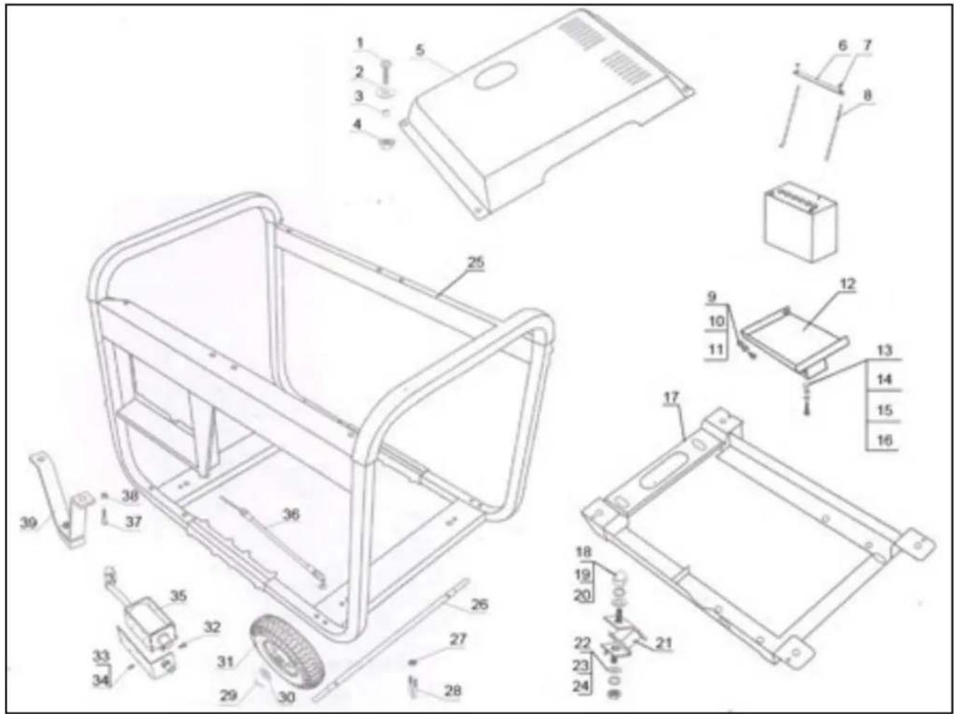
Technical diagram of a device's internal components with numbered parts, including chassis, casing, and accessories.Frame Assembly
| No | Description | No | Description |
| 1 | Bolt M6x22 | 21 | Rubber mount |
| 2 | Big Flat washer 6 | 22 | Nut M10 |
| 3 | Sheath | 23 | Spring washer 10 |
| 4 | Cushion | 24 | Flat washer 10 |
| 5 | Engine Cover | 25 | Generator frame |
| 6 | Battery tie down | 26 | Axle |
| 7 | Butterfly nut M6 | 27 | Nut M6 |
| 8 | Tie down hooks | 28 | U bolt |
| 9 | Nut M6 | 29 | Split pin |
| 10 | Bolt M6x40 | 30 | Big Flat washer 20 |
| 11 | Flat washer 6 | 31 | Solid wheels |
| 12 | Battery tray | 32 | Screw M3x8 |
| 13 | Bolt M10x20 | 33 | Spring washer 3 |
| 14 | Spring washer 10 | 34 | Flat washer 3 |
| 15 | Flat washer 10 | 35 | Electromagnet |
| 16 | Nut M10 | 36 | Throttle cable |
| 17 | Bracket | 37 | Bolt M8x40 |
| 18 | Nut M10 | 38 | Nut M8 |
| 19 | Spring washer 10 | 39 | Bracket |
| 20 | Flat washer 10 |

text_image
Technical diagram of an electronic device with numbered components for identification| Electric Panel | |||||
| No | Description | No | Description | No | Description |
| 1 | Steel panel | 7 | Rectifier | 13 | Starter switch |
| 2 | Red wire holder | 8 | Breaker | 14 | Wiring harness |
| 3 | Black wire holder | 9 | Relay | 15 | Electric box |
| 4 | Grounded bolt | 10 | Hour meter | 16 | Nut M6x12 |
| 5 | Socket 230V / 400V | 11 | Voltmeter | ||
| 6 | DC fuse | 12 | Oil alert lamp | ||
text_image
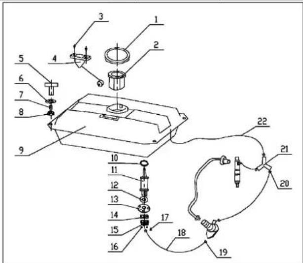
Technical diagram of a mechanical assembly with numbered components for identification| Fuel System | |||||
| No | Description | No | Description | No | Description |
| 1 | Fuel tank cover | 9 | Fuel tank | 17 | Screwe M5x10 |
| 2 | Cup of fuel filter | 10 | Gasket-filtering core | 18 | Fuel inlet pipe |
| 3 | Screw M5x10 | 11 | Fuel filter | 19 | Clip 13 |
| 4 | Buoy for oil level indication | 12 | Gasket-fuel filter | 20 | Clip 9 |
| 5 | Bolt M6x22 | 13 | Fuel filter connect cover | 21 | Pipe tee |
| 6 | Big Flat washer 6 | 14 | Gasket-fuel drain | 22 | Fuel overfill pipe |
| 7 | Sheath | 15 | Fuel drain cock | ||
| 8 | Cushion | 16 | Nut M6 | ||
29.2 STE 7500DSH

text_image
Technical diagram of a mechanical assembly with numbered components for identification1、Diesel Engine Assembly
| No. | Part.NO | Description | Qty. |
| 1 | Air Cooled Diesel | 1 | |
| 2 | Bolt M8*16 | 2 | |
| 3 | Front Air Cover Weldment | 1 | |
| 4 | Bolt M8*16 | 2 | |
| 5 | Buffer Support Assy | 1 | |
| 6 | Bolt M6*22 | 2 | |
| 7 | Fuel Pipe Pressure Plate Assy | 2 | |
| 8 | Rear Air Cover Weldment | 1 | |
| 9 | Bolt M6*12 | 3 |
text_image
Exploded view diagram of an electric motor assembly with numbered components2、Electric Machine Assembly
| No. | Part.NO | Description | Qty. |
| 1 | Three-phrase Electrical Machinery Assembly | 1 | |
| 2 | Electrical Machinery Forepart Cover | 1 | |
| 3 | Self-Tapping Locking Screw M5 | 3 | |
| 4 | Bolt M8*30 | 4 | |
| 5 | Electrical Machinery Fan | 1 | |
| 6 | Generator Rotator | 1 | |
| 7 | Clip Ring | 1 | |
| 8 | Pull-through Shaft Bolt Washer | 1 | |
| 9 | Pull-through Shaft Bolt M10*265 | 1 | |
| 10 | Electrical Machinery Control Plate | 1 | |
| 11 | Electrical Machinery Stator | 1 | |
| 12 | Bolt M5 | 2 | |
| 13 | Electrical Machinery Rare Cover | 1 | |
| 14 | Bolt M6*185 | 4 | |
| 15 | Carbon Brush | 1 | |
| 16 | Grate Rectifier | 1 | |
| 17 | Excitation AVR | 1 | |
| 18 | Electrical Machinery Booting Air Cover | 1 | |
| 19 | Self-tapping Locking Screw | 2 |

text_image
Technical diagram of a mechanical assembly with numbered components and exploded view1、Chassis Assembly
| No. | Part NO | Description | Qty. |
| 1 | Bolt M6*18 | 13 | |
| 2 | Accumulator Supporter | 1 | |
| 3 | Accumulator Supporter Washer | 2 | |
| 4 | Chassis Weldment | 1 | |
| 5 | Foot Wheel | 4 | |
| 6 | Cotter Pin | 4 | |
| 7 | Nut M10 | 14 | |
| 8 | Elastic Gasket 10 | 14 | |
| 9 | Gasket 10 | 16 | |
| 10 | Brake spring Assembly | 1 | |
| 11 | Cushion Assy | 4 | |
| 12 | Housing Base Weldment | 1 | |
| 13 | Lower Body of Heat Insulation Weldment | 1 | |
| 14 | Heat Insulation Cover | 1 | |
| 15 | Supporter of Heat Insulation Weldment | 1 | |
| 16 | Bolt M10*45 | 6 |

text_image
Exploded view diagram of a refrigerator with numbered components for identification2、Housing Unit Assembly
| No. | Part.NO | Description | Qty. |
| 1 | Housing Weldment | 1 | |
| 2 | Door Seal Pad | 1 | |
| 3 | Wheel cover | 4 | |
| 4 | Bolt M6*16 | 58 | |
| 5 | Big Gasket | 58 | |
| 6 | Sponge | 1 | |
| 7 | Right Side Plate Weldment | 1 | |
| 8 | Air Cleaner Cover | 1 | |
| 9 | Rear Plate Weldment | 1 | |
| 10 | Observation hole cover | 1 | |
| 11 | Fuel tank Vent Cushion | 1 | |
| 12 | Window Mount Sheath and Plexiglass | 1 | |
| 13 | Left Side Plate Weldment | 1 | |
| 14 | Radiator Unit | 1 | |
| 15 | Asbestos | 1 | |
| 16 | Screw M5*12 | 4 | |
| 17 | Lock | 1 |

text_image
Technical diagram of a mechanical device with numbered components for identification5、Fuel System
| No. | Part.NO | Description | Qty. |
| 1 | Fuel Tank Weldment | 1 | |
| 2 | Cushion | 4 | |
| 3 | Sheath | 4 | |
| 4 | Big Gasket 6 | 4 | |
| 5 | Bolt M6*22 | 4 | |
| 6 | Oil Indicator Assy | 1 | |
| 7 | Screw M5*12 | 2 | |
| 8 | Fuel Tank Cover Assy | 1 | |
| 9 | Filler Filter | 1 | |
| 10 | Clip Φ9 | 4 | |
| 11 | Three way pipe | 1 | |
| 12 | Oil Return Pipe | 3 | |
| 13 | Clip Φ8 | 2 | |
| 14 | Clip Φ13 | 2 | |
| 15 | Fuel Pipe | 2 | |
| 16 | Clip Φ12 | 2 | |
| 17 | Fuel Filter Core | 1 |
text_image
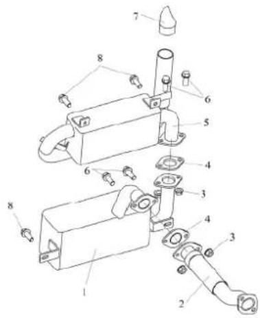
Technical diagram of a mechanical assembly with numbered components for identification6、Muffler Assembly
| No. | Part.NO | Description | Qty. |
| 1 | One-lever Muffler Assy | 1 | |
| 2 | Exhaust Pipe Assy | 1 | |
| 3 | Nut M8 | 4 | |
| 4 | Exhaust Pipe Washer | 2 | |
| 5 | Second-lever Muffler Assy | 1 | |
| 6 | Bolt M8*25 | 4 | |
| 7 | End Gas Outlet Hose | 1 | |
| 8 | Bolt M8*16 | 4 |
text_image
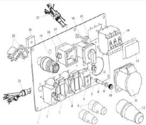
Technical diagram of an electrical component with numbered parts, likely an electrical relay or motor assembly.7、Panel Assembly
| No. | Part NO | Description | Qty |
| 1 | Instrument Panel | 1 | |
| 2 | Liquid magnetic circuit breaker 1P14A | 1 | |
| 3 | Waterproof cover 1P | 1 | |
| 4 | 16A250V European Receptacle | 2 | |
| 5 | 16A250V European Pin | 2 | |
| 6 | T-type socket | 1 | |
| 7 | Overload Switch | 1 | |
| 8 | Bolt M6*22 | 1 | |
| 9 | Nut M6 | 1 | |
| 10 | Grounding Screw Cap | 1 | |
| 11 | 16A 380-415V Three-phase Receptacle | 1 | |
| 12 | 16A 380-415V Three-phase Pin | 1 | |
| 13 | Waterproof cover 3P | 1 | |
| 14 | Liquid magnetic circuit breaker 3P8A | 1 | |
| 15 | Pressure relief valve | 1 | |
| 16 | Transformation Switch | 1 | |
| 17 | Volunteer 0-450V | 1 | |
| 18 | Oil Pressure Alerting Lamp | 1 | |
| 19 | Nating Key | 1 | |
| 20 | Reactor bridge | 1 | |
| 21 | Circuitry Setting Sheath | 1 | |
| 22 | Relay | 2 | |
| 23 | Wiring Harness Setting Sheath | 1 |

text_image
Technical diagram of an electrical component with numbered parts labeled 1 through 88、Accumulator
| No. | Parl.NO | Description | Qty. |
| 1 | Accumulator 12V 30Ah | 1 | |
| 2 | Accumulator Mount Rod | 2 | |
| 3 | Accumulator Washer | 1 | |
| 4 | Generator Wiring Earth Terminal | 1 | |
| 5 | Accumulator Cathode Wiring Clip | 1 | |
| 6 | Accumulator Pressure Plate | 1 | |
| 7 | Batterfly Nut M6 | 2 | |
| 8 | Accumulator Positive Wiring Clip | 1 |
30 ERSATZTEILE / SPARE PARTS / REZERVNI DELI / PIECES DE RECHANGE
30.1 Ersatzteilbestellung / spare parts order / Naročanje rezervnih delov / Commande de pièces détachées
(EN) With original ZIPPER spare parts you use parts that are attuned to each other shorten the installation time and elongate your machines lifespan.
NOTICE
The installation of other than original spare parts voids the warranty!
So you always have to use original spare parts
When you place a spare parts order please use the service formular you can find in the last chapter of this manual. Always take a note of the machine type, spare parts number and partname. We recommend to copy the spare parts diagram and mark the spare part you need.
Or use the electronic ordering opportunity via the spare parts catalogue or spare parts request form on our homepage
You find the order address in the preface of this operation manual.
Company ZIPPER Maschinen GmbH grants for mechanical and electrical components a warranty period of 2 years for amateur use; and warranty period of 1 year for professional use, starting with the purchase of the final consumer. In case of defects during this period, which are not excluded by paragraph 3, ZIPPER will repair or replace the machine at its own discretion.
2.) Report:
In order to check the legitimacy of warranty claims, the final consumer must contact his dealer. The dealer has to report in written form the occurred defect to ZIPPER. If the warranty claim is legitimate, ZIPPER will pick up the defective machine from the dealer. Returned shippings by dealers which have not been coordinated with ZIPPER, will not be accepted and refused.
3.) Regulations:
a) Warranty claims will only be accepted, when a copy of the original invoice or cash voucher from the trading partner of ZIPPER is enclosed to the machine. The warranty claim expires if the accessories belonging to the machine are missing.
b) The warranty does not include free checking, maintenance, inspection or service works on the machine. Defects due to incorrect usage of the final consumer or his dealer will not be accepted as warranty claims either. Some examples: usage of wrong fuel, frost damages in water tanks, leaving fuel in the tank during the winter, etc.
c) Defects on wear parts are excluded, e.g. carbon brushes, collection bags, knives, cylinders, cutting blades, clutches, sealings, wheels, saw blades, splitting crosses, riving knives, riving knife extensions, hydraulic oils, oil/air/fuel filters, chains, spark plugs, sliding blocks, etc.
d) Also excluded are damages on the machine caused by incorrect or inappropriate usage, if it was used for a purpose which the machine is not supposed to, ignoring the user manual, force majeure, repairs or technical manipulations by not authorized workshops or by the customer himself, usage of non-original ZIPPER spare parts or accessories.
e) After inspection by our qualified personnel, resulted costs (like freight charges) and expenses for not legitimated warranty claims will be charged to the final customer or dealer.
f) In case of defective machines outside the warranty period, we will only repair after advance payment or dealer's invoice according to the cost estimate (incl. freight costs) of ZIPPER.
g) Warranty claims can only be granted for customers of an authorized ZIPPER dealer who directly purchased the machine from ZIPPER. These claims are not transferable in case of multiple sales of the machine.
4.) Claims for compensation and other liabilities:
The liability of company ZIPPER is limited to the value of goods in all cases. Claims for compensation because of poor performance, lacks, damages or loss of earnings due to defects during the warranty period will not be accepted. ZIPPER insists on its right to subsequent improvement of the machine.
34 GARANCIJA (SL)
1.) Garancija:
Product experience form
We observe the quality of our delivered products in the frame of a Quality Management policy.
Your opinion is essential for further product development and product choice. Please let us know about your:
- Impressions and suggestions for improvement.
- experiences that may be useful for other users and for product design
- Experiences with malfunctions that occur in specific operation modes
We would like to ask you to note down your experiences and observations and send them to us via FAX, E-Mail or by post:
* (Mobil)telefon / (mobile) phone International numbers with country code
Fax
2. Geräteinformationen / tool information
Seriennummer/serial number: ____ *Maschinentype/machine type:
Please describe amongst others in the problem: What has cause the problem/defect, what was the last activity before you noticed the problem/defect? For electrical problems: Have you had checked you electric supply and the machine already by a certified electrician?
3. Bitte beachten
/ Additional information
INCOMPLETELY FILLED SERVICE FORMS CANNOT BE PROCESSED! FOR GUARANTEE CLAIMS PLEASE ADD A COPY OF YOUR ORIGINAL SALES / DELIVERY RECEIPT OTHERWISE IT CANNOT BE ACCEPTED. FOR SPARE PART ORDERS PLEASE ADD TO THIS SERVICE FORM A COPY OF THE RESPECTIVE EXPLODED DRAWING WITH THE REQUIRED SPARE PARTS BEING MARKED CLEARLY AND UNMISTAKABLE. THIS HELPS US TO IDENTIFY THE REQUIRED SPARE PARTS FASTLY AND ACCEL- LERATES THE HANDLING OF YOUR INQUIRY.