SPHP 130 - Heating QLIMA - Free user manual and instructions
Find the device manual for free SPHP 130 QLIMA in PDF.

| Brand | Qlima |
| Model | SPHP 130 |
| Product type | Heat pump for pool |
| Power supply | 220-240 V~ / 50 Hz, grounded plug |
| Heating power | Not specified (suitable for residential pool) |
| Operating temperature range | Ambient air: 8 °C to 43 °C |
| Set temperature | 15 to 40 °C (adjustable), default 27 °C |
| Refrigerant | R32 (fluorinated gas, GWP = 675) |
| Main functions | Pool water heating, automatic defrost, antifreeze protection, automatic restart |
| Maintenance and cleaning | Clean the casing with a damp cloth, vacuum the evaporator with a soft brush. Annual maintenance by a professional (electrical checks, safety, refrigerant). |
| Hydraulic installation | Inlet/outlet connections of 32/38 mm diameter. Install after the filter and before the treatment system. |
| Electrical installation | Connect to a circuit with residual current device and circuit breaker. The filter pump must run at the same time. |
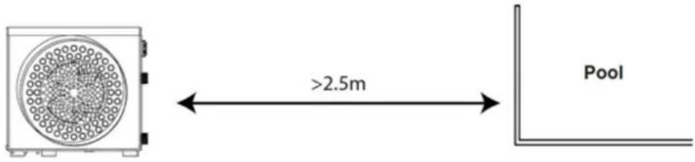
| Minimum distance from pool | 2.5 meters |
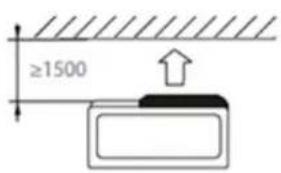
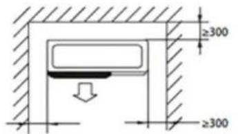
| Required clearances | Front: 1.5 m; sides and back: 30 cm; nothing above |
| Protection | Low pressure protection, antifreeze protection, fault shutdown (error codes P1, P3, P5, P7, E3, E6) |
| Warranty | 24 months from purchase date, subject to compliance with instructions |
| Weight | Not specified |
| Dimensions | Not specified |
Frequently Asked Questions - SPHP 130 QLIMA
User questions about SPHP 130 QLIMA
0 question about this device. Answer the ones you know or ask your own.
Ask a new question about this device
Download the instructions for your Heating in PDF format for free! Find your manual SPHP 130 - QLIMA and take your electronic device back in hand. On this page are published all the documents necessary for the use of your device. SPHP 130 by QLIMA.
USER MANUAL SPHP 130 QLIMA
natural_image
Exterior view of a Qlima air purifier unit with circular vent grille (no text or symbols visible)guarantee
2
YEARS
| D | GEBRAUCHSANWEISUNG | 2 |
| E | INSTRUCCIONES DE USO | 18 |
| F | MANUEL D'UTILISATION | 34 |
| GB | OPERATING MANUAL | 50 |
| I | ISTRUZIONI D'USO | 66 |
| NL | GEBRUIKSAANWIJZING | 82 |
natural_image
Abstract black-and-white geometric pattern with diagonal lines and a central emblem (no text or symbols)
ACHTUNG!
natural_image
Line drawing of a rectangular industrial device with circular vent and three ports (no text or symbols)natural_image
Simple line drawing of a plug inserted into an electrical outlet (no text or symbols)E NUTZUNG
BEDIENFELD

① Betriebs-LED
③ ON-/OFF-Taste
⑤ Auf-Taste (+)
② Defrost-LED
④ Select-Taste
6 Ab-Taste (-)
HEIZMODUS

WARNUNG
natural_image
Abstract black-and-white graphic with diagonal lines and a stylized animal figure (no text or symbols)
¡ATENCIÓN!
① Panel frontal
natural_image
Line drawing of a rectangular electronic device with circular vent and three ports (no text or symbols)natural_image
Line drawing of a plug-in socket connected to a cable, with a connector inserted (no text or symbols)E uso
PANEL DE MANDO

① LED de encendido
natural_image
Abstract black-and-white geometric pattern with diagonal lines and a central emblem (no text or symbols)
ATTENTION!
natural_image
Line drawing of a rectangular industrial device with circular vent and three ports (no text or symbols)natural_image
Simple line drawing of a plug-in socket connected to a power strip (no text or symbols)E UTILISATION
PANNEAU DE COMMANDE
③ Bouton MARCHE/ARRÊT
⑤ Bouton (+) Haut
② LED de dégivrage
CONDITIONS DE GARANTIE
Congratulations on the purchase of your Qlima pool heat pump. You have acquired a high quality product that, if used responsibly, will give you many years of pleasure.
Please read these instructions for use first in order to ensure the maximum life span of your pool heat pump.
On behalf of the manufacturer, we provide a 24-month guarantee on all material and production defects.
Please enjoy your pool heat pump.
Yours sincerely,
PVG Holding b.v.
Customer service department
-
READ THE DIRECTIONS FOR USE FIRST.
-
IN CASE OF ANY DOUBT, CONTACT YOUR DEALER.
CONTENTS
A SAFETY INSTRUCTIONS
B. PARTS NAMES
C. GENERAL
D. INSTALLATION
E. USE
F. OPERATION
G. MAINTENANCE AND SERVICING
H. TROUBLE SHOOTING TIPS
I. GUARANTEE CONDITIONS
READ THIS MANUAL
Inside you will find many helpful hints on how to use and maintain your pool heat pump properly. You will find many answers to common problems in the chapter Troubleshooting Tips. If you review chapter H "Troubleshooting Tips" first, you may not need to call for service.
A SAFETY INSTRUCTIONS
Install this device only when it complies with local/national legislation, ordinances and standards. This product is intended to be used as a pool heat pump for residential pools. Check the mains voltage and frequency. This unit is only suitable for earthed sockets, connection voltage 220-240 V\~ / 50 Hz.

IMPORTANT
- The device MUST always have an earthed connection. If the power supply is not earthed, you may not connect the unit. The plug must always be easily accessible when the unit is connected. Read these instructions carefully and follow the instructions.
- The pool heat pump contains a refrigerant and can be classified as pressurized equipment. Therefore always use an authorized air conditioning engineer for maintenance of the pool heat pump.
Before connecting the unit, check the following:
- The voltage supply must correspond with the mains voltage stated on the rating label.
- The socket and power supply must be suitable for the current stated on the rating label.
- The plug on the cable of the device must fit into the wall socket.
- The device must be placed on a stable surface.
The electricity supply to the device must be checked by a recognised professional if you have any doubts regarding the compatibility.
- This device is manufactured according to CE safety standards. Nevertheless, you must take care, as with any other
GB
electrical device.
- Do not cover the air inlet and outlet grill.
- Never allow the device to come into contact with chemicals.
- Never spray the unit with or submerge in water.
- Do not insert hands, fingers or objects into the openings of the unit.
- Never use an extension cable to connect the device to the electric power supply. If there is no suitable, earthed wall socket available, have one installed by a recognised electrician.
- Have any repairs and/or maintenance only carried out by a recognised service engineer or your recognised supplier. Follow the instructions for use and maintenance as indicated in the user manual of this device.
- Always remove the plug of the unit from the wall socket when it is not in use.
- Do not operate or stop the pool heat pump by inserting or pulling out the power plug. Only use the dedicated buttons on the pool heat pump or on the remote control.
- Do not open the pool heat pump when it is in operation. Always pull out the electrical plug when opening the device.
- Always pull out the electrical plug when cleaning or servicing the pool heat pump.
- Do not place gas burners, ovens and/or stoves in the air-stream.
- Do not operate the buttons or touch the pool heat pump with wet hands.
- Note that the unit produces sound when in use, this could interfere with local legislation, it is the responsibility of the user to check and to make sure the equipment is in full compliance with local legislation.
- This appliance is not intended for use by persons (including children) with reduced physical, sensory or mental capabilities, or lack of experience and knowledge, unless they have been given supervision or instruction
concerning use of the appliance by a person responsible for their safety.
- Children should be supervised to ensure that they do not play with the appliance.
- It is advised to stay out of the direct air stream.
- Do not make any modifications to the unit.
- If the power cable is damaged it must be replaced by the manufacturer, its customer service department or persons with comparable qualifications in order to prevent danger.
- This appliance can be used by children aged from 8 years and above and persons with reduced physical, sensory or mental capabilities or lack of experience and knowledge if they have been given supervision or instruction concerning use of the appliance in a safe way and understand the hazards involved. Children shall not play with the appliance. Cleaning and user maintenance shall not be made by children without supervision.
- The equipment must always be stored and transported vertically on a pallet and in its original packaging. If it is stored or transported horizontally, wait at least 24 hours before switching it on.

natural_image
Abstract black-and-white graphic with diagonal lines and a stylized hand holding a gear (no text or symbols)
ATTENTION!
- Never use the device with a damaged power cord, plug, cabinet or control panel.
- Failing to follow the instructions may lead to nullification of the guarantee on this device.
NOTE ABOUT FLUORINATED GASSES
- This pool heat pump unit contains fluorinated gasses. For specific information on the type of gas and the amount, please refer to the relevant label on the unit itself.
- Installation, service, maintenance and repair of this unit must be performed by a certified technician.
- Product recycling must be performed by a certified technician.
- This pool heat pump unit is a hermetically sealed unit that contains fluorinated gasses.
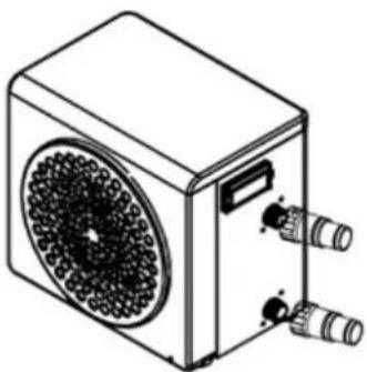
B PART NAMES
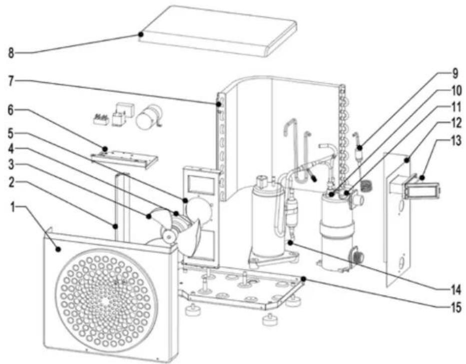
① Front panel
② Mounting frame
③ Fan blade
④ Fan motor
⑤ Fan support
6 Electrical control box
⑦ Evaporator
⑧ Top panel
⑨ Throttling parts
⑩ Heat exchanger
⑪ Water Flow Switch
⑫ Left side panel
13 Control panel
14 Compressor
⑮ Base frame
PACKAGE CONTENTS
- Heat pump
• 2 hydraulic inlet/outlet connectors 32/38mm diameter
• This installation and user manual
• 4 anti-vibration pads

NOTE!
All the pictures in this manual and on the gift box are for explanation and indication purpose only. They may be slightly different from the pool heat pump you purchased. The actual shape shall prevail.
WIRING DIAGRAMS
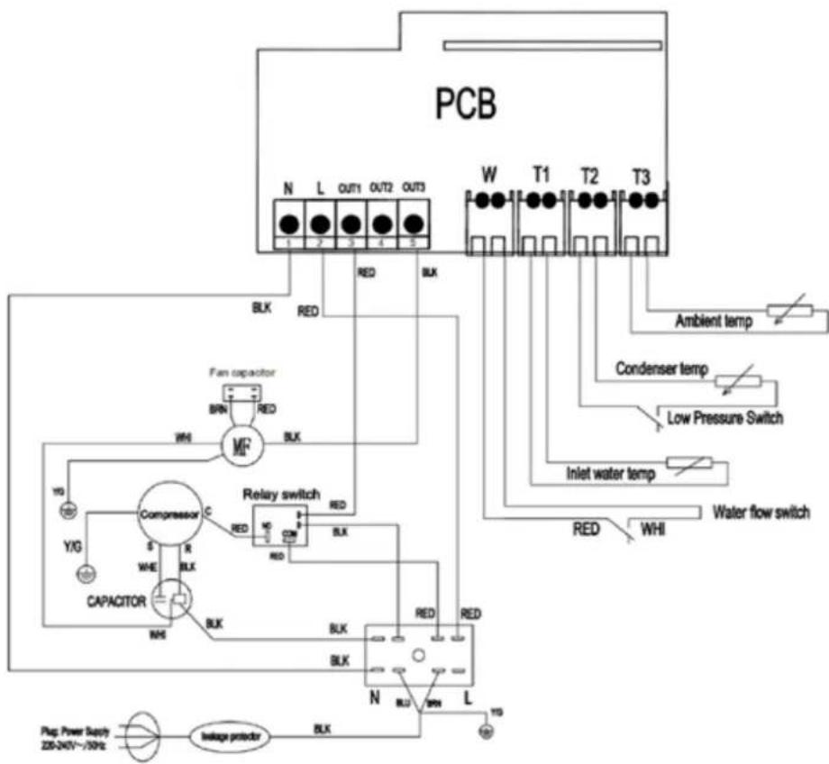
flowchart
graph TD
    A["PCB"] --> B["N"]
    A --> C["L"]
    A --> D["OUT1"]
    A --> E["OUT2"]
    A --> F["OUT3"]
    B --> G["BLK"]
    C --> H["RED"]
    D --> I["RED"]
    E --> J["RED"]
    F --> K["RED"]
    L["Condenser temp"] --> M["Low Pressure Switch"]
    N["Inlet water temp"] --> O["Water flow switch"]
    P["Ambient temp"] --> Q["BLK"]
    R["Fan capacitor"] --> S["BRIN"]
    R --> T["RED"]
    U["Capacitor"] --> V["M²"]
    W["Relay switch"] --> X["BLK"]
    Y["Compressor"] --> Z["C"]
    AA["BLK"] --> AB["S"]
    AC["BLK"] --> AD["R"]
    AE["BLK"] --> AF["WHE"]
    AG["BLK"] --> AH["NH"]
    AI["BLK"] --> AJ["L"]
    AK["BLK"] --> AL["N"]
    AM["BLK"] --> AN["RLJ"]
    AO["BLK"] --> AP["RLJ"]
    AQ["BLK"] --> AR["RLJ"]
    AS["PLag. Power Supply ZBT-240V~750Hz"] --> AT["Inlager protector"]
    AU["BLK"] --> AV["BLK"]
C GENERAL
DURING USE
• To avoid serious injuries, never touch the fan when it is operating.
- Keep the heat pump out of the reach of children to avoid serious injuries caused by the heat exchanger's blades.
- Never start the equipment if there is no water in the pool or if the circulating pump is stopped.
- Check the water flow rate every month and clean the filter if necessary.
DURING CLEANING
- Switch off the equipment's electricity supply.
- Close the water inlet and outlet valves.
- Do not insert anything into the air or water intakes or outlets.
- Do not rinse the equipment with water.
WATER TREATMENT
Heat pumps for swimming pools can be used with all types of water treatment systems.
Nevertheless, it is essential that the treatment system (chlorine, pH, bromine and/or salt chlorinator metering pumps) is installed after the heat pump in the hydraulic circuit.
To avoid any deterioration to the heat pump, the water's pH must be maintained between 6.9 and 8.0.
The heat pump is very easy to install, only water and power need to be connected during installation.
LOCATION
The heat pump should be located at least 2.5 meter away from the swimming pool.
Please comply with the following rules concerning the choice of heat pump location.
- The unit's future location must be easily accessible for convenient operation and maintenance.
- It must be installed on the ground, laid ideally on a level concrete floor. Ensure that the floor is sufficiently stable and can support the weight of the unit.
- Check that the unit is properly ventilated, that the air outlet is not facing the windows of neighboring buildings and that the exhaust air cannot return. In addition, provide sufficient space around the unit for servicing and maintenance operations.
- The unit must not be installed in an area exposed to oil, flammable gases, corrosive products, sulfurous compounds or close to high frequency equipment.
- To prevent mud splashes, do not install the unit near a road or track.
- To avoid causing nuisance to neighbors, make sure the unit is installed so that it is positioned towards the area that is least sensitive to noise.
- Keep the unit as much as possible out of the reach of children.
Dimensions in mm
Place nothing less than 1,50 m in front of the heat pump.
Leave 30 cm of empty space around the sides and rear of the heat pump.
Do not leave any obstacle above or in front of the unit!
D INSTALLATION
INSTALLATION LAYOUT
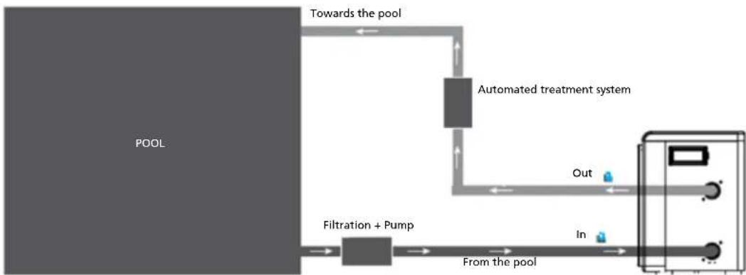
flowchart
graph LR
    A["POOL"] --> B["Filtration + Pump"]
    B --> C["From the pool"]
    C --> D["Automated treatment system"]
    D --> E["Towards the pool"]
    D --> F["Out"]
    D --> G["In"]
The filter located upstream of the heat pump must be regularly cleared so that the water in the system is clean, thus avoiding the operational problems associated with dirt or clogging in the filter.
HYDRAULIC CONNECTION
natural_image
Line drawing of a rectangular electronic device with circular vent and three ports (no text or symbols)Step 1 Screw the connectors to the heat pump
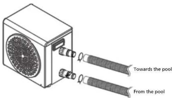
Step 2 Connect the water outlet pipe and the water intake pipe
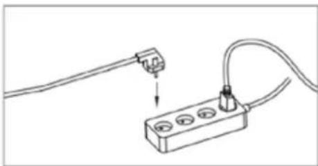
ELECTRICAL CONNECTION
Before connecting your heat pump, please ensure that the plug is connected to the ground.
The filter pump should function at the same time as the heat pump. Therefore, you need to connect them to the same electrical circuit.
natural_image
Line drawing of a plug inserted into an electrical outlet with wires (no text or symbols)E USE
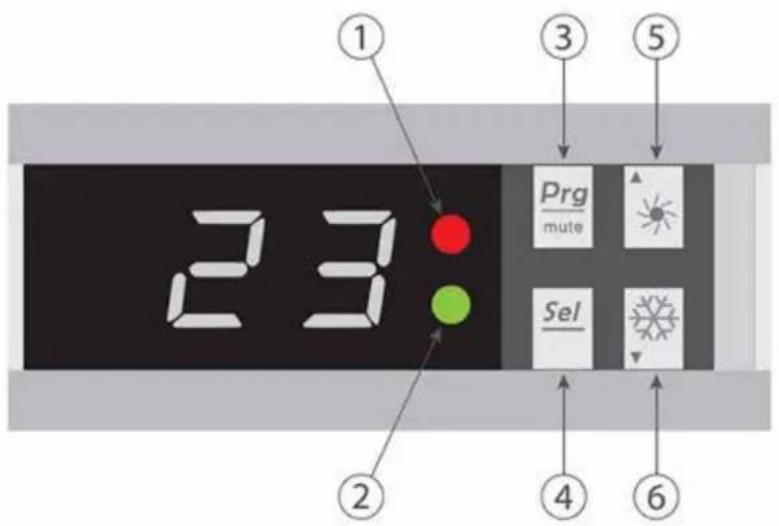
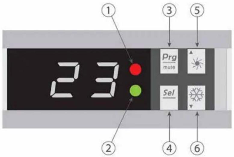
CONTROL PANEL

① Power LED
③ ON/OFF button
⑤ Up (+) button
② Defrost LED
4 Select button
6 Down (-) button
HEATING MODE

WARNING
Before starting, ensure that the filtration pump is operating correctly.
Step 1: Press to switch on your pump.
Step 2: Using buttons and select the required temperature.
EXAMPLE:
If the current temperature is 15^ C, default setting temperature is 27^ required temperature is 30^ C.
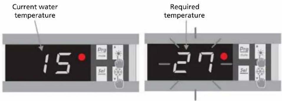
USEFUL INFORMATION ABOUT HOW THE HEATING MODE OPERATES
When the incoming water temperature is less than or equal to the required temperature (setpoint temperature) -X°C, the heat pump will switch to heating mode. The compressor will stop when the temperature of the incoming water is greater than or equal to the required temperature (setpoint temperature).
Indicators for adjustment range X and Y
X: adjustable parameter from 1° to 15°C, default setting is 3°C. (Parameter N°6)
STATUS VALUES AND ADVANCED SETTINGS

WARNING
This operation is used to assist servicing and future repairs. The default settings should only be modified by an experienced professional person.
The system's settings can be checked and adjusted via the remote control by following these steps
- Keeppressing until you enter the settings verification mode.
- Press and for see the parameters.
- Press to select the setting to be modified.
Note, some settings cannot be modified. Consult the settings table for further information.
- Press and to adjust the setting value.
- Press to set the new value.
- Pressto return to the main screen.
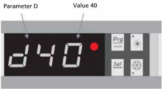
PARAMETERS TABLE
| N° Description Adjustment | range | Factory setting | Remarks | |
| A Water intake temperature -19~99°C Actual data | ||||
| b Water outlet temperature -19~99°C Actual data | ||||
| c Ambient air temperature -19~99°C Actual data | ||||
| d Setting temperature 15~40°C 27°C Adjustable | ||||
| E Defrost auto-activation time 10~80 min 40 min Adjustable | ||||
| F | Maximum defrost duration | 10~40 min | 30 min | Adjustable |
| H | Adjustment of temperature difference for restart | 1~10°C | 3°C | Adjustable |
| J Automatic restart | 0 = OFF1 = ON | 1 | Adjustable | |
| O | Antifreeze protection - low air temperature | 0~15°C | 8°C | Adjustable |
| P | Evaporator temperature to enter defrosting mode | -19°C~0°C | -3°C | Adjustable |
| U | Evaporator temperature to exit defrosting mode | 1~30°C | 20°C | Adjustable |
| t Reserved - do not modify | Reserved | |||
F OPERATION
Conditions of use
For the heat pump to operate normally, the ambient air temperature must be between 8^ C and 43^ C.
Recommendations prior to start-up
Before activating the heat pump, please:
- Check that the unit is stable.
• Control the proper functioning of your electrical installation. - Check that the hydraulic connections are tight and that there is no leakage of water.
- Remove any unnecessary object or tool from around the unit.
Operation
- Connect the unit power plug.
- Activate the circulating pump.
- Activate the unit's power supply protection (differential switch and circuit-breaker).
- Activate the heat pump by pressing once on .
- Select the required temperature.
- The heat pump's compressor will start up after a few moments.
All you have to do now is wait until the required temperature is reached.

WARNING
Under normal conditions, a suitable heat pump can heat the water in a swimming pool by 1^ C to 2^ C per day. It is therefore quite normal to not feel any temperature difference in the system when the heat pump is working.
A heated pool must be covered to avoid any loss of heat.
G MAINTENANCE AND SERVICING

WARNING
Before undertaking maintenance work on the unit, ensure that you have disconnected the electrical power supply.
Cleaning
The heat pump's casing must be cleaned with a damp cloth. The use of detergents or other household products could damage the surface of the casing and affect its properties.
The evaporator at the rear of the heat pump must be carefully cleaned with a vacuum cleaner and soft brush attachment.
Annual maintenance
The following operations must be undertaken by a qualified person at least once a year.
- Carry out safety checks.
- Check the integrity of the electrical wiring.
- Check the earthing connections.
- Monitor the state of the pressure gauge and the presence of refrigerant.
Winter storage
Your heat pump is designed to operate in rainy weather conditions and withstand frost using a specially created anti-frost technology. However it is not recommended to leave it outside for long periods of time (eg over winter). After draining down the pool for the winter, store the heat pump in a dry place.

WARNING
Under normal conditions, a suitable heat pump can heat the water in a swimming pool by 1^ C to 2^ C per day. It is therefore quite normal to not feel any temperature difference in the system when the heat pump is working.
A heated pool must be covered to avoid any loss of heat.
H TROUBLE SHOOTING TIPS
BREAKDOWNS AND FAULTS

TROUBLE
Stop the pool heat pump immediately if one of the following faults occur. Disconnect the power and contact your supplier.
- Fuse blows frequently or circuit breaker trips frequently.
- Other objects or water penetrate the pool heat pump.
• Other abnormal situations.
In the event of a problem, the heat pump's screen displays an error code instead of temperature indications. Please consult the table below to find the possible causes of a fault and the actions to be taken.
| Code Fault Possible causes Action | |||
| P1 | Water intake temperature sensor malfunction | Sensor badly connected Reconnect sensor | Sensor |
| Sensor defective Replace sensor | |||
| Defective control panel | Replace control panel | ||
| P3 | Evaporator temperature sensor malfunction | Same causes as P1 Same actions as P1 | |
| P5 | External temperature sensor malfunction | ||
| P7 Antifreeze protection | Protection activated when the ambient temperature is too low. | No intervention is necessary | |
| E3 Flow sensor malfunction | Insufficient water in heat exchanger | Check your water circuit operation | |
| Defective water flow sensor | Replace water flow switch | ||
| Defective control panel | Replace control panel | ||
| E6 Low pressure protection | Insufficient refrigerant gas | Recharge refrigerant gas | |
| Pressure switch not connected well or defective | Connect of replace the pressure switch | ||
| Control panel defective | Replace control panel | ||
| The unit stop working without error code | Insufficient water in heat exchanger | Check your water circuit operation | |
| Defective control panel | Replace control panel | ||

NOTE!
If problem persists, contact a local dealer or your nearest customer service center. Provide them with a detailed description of the unit malfunction as well as your model number.
If the trouble has not been corrected, please contact your supplier. Be sure to inform them of the detailed malfunctions and unit model.

NOTE!
Reparation of the device should only be done by an authorized air conditioning engineer.
I GUARANTEE CONDITIONS
The pool heat pump is supplied with a 24-month guarantee on other components, commencing on the date of purchase. The following rules apply:
- We expressly refuse all further damage claims, including claims for collateral damage.
- Repairs to or replacement of components within the guarantee period will not result in an extension of the guarantee.
- The guarantee is invalidated if any modifications have been made, non genuine parts are fitted or repairs are carried out by third parties.
- Components subject to normal wear are not covered by the guarantee.
- The guarantee is valid only when you present the original, dated purchase invoice and if no modifications have been made.
- The guarantee is invalid for damage caused by neglect or by actions that deviate from those in this instruction booklet.
- Transportation costs and the risks involved during the transportation of the pool heat pump or pool heat pump components shall always be for the account of the purchaser.
- Damage caused by not using suitable filters is not covered by the guarantee.
- Refrigerant loss and/or leakage because of incompetent (dis)connecting of the units and/or (dis-) connection of the units by not qualified personnel is not covered by the guarantee conditions applicable to this product. Damage to units which are mounted, connected and/or disconnected not following local law and/or legislation and/or not following the guidelines in this manual is not covered by the guarantee conditions applicable to this product.
Consult your dealer for repairs if these instructions do not provide a solution. Make sure that in the unlikely case of needed disconnection, that disconnection is always done by qualified, authorized personnel and according to your local laws and legislation.
Do not dispose of electrical appliances as unsorted municipal waste, use separate
collection facilities. Contact your local government for information regarding the collection systems available. If electrical appliances are disposed of in landfills or dumps, hazardous substances can leak into the groundwater and get into the food chain, damaging your health and well-being. When replacing old appliances with new once, the retailer is legally obligated to take back your old appliance for disposal at least for free of charge. Do not throw batteries into the fire, where they can explode or release dangerous liquids. If you replace or destroy the remote control, remove the batteries and throw them away in accordance with the applicable regulations because they are harmful to the environment.
Environmental information: This equipment contains fluorinated greenhouse gases covered by the Kyoto Protocol. It should only be serviced or dismantled by professional trained personnel.
This equipment contains R32 refrigerant in the amount as stated in the table above. Do not vent R32 into atmosphere: R32, is a fluorinated greenhouse gas with a Global Warming Potential (GWP) = 675
Internet:
For your convenience you can download the latest version of the user-, installation- and/or service manual on www.Qlima.com
Gentile signora, egregio signore,
natural_image
Abstract black-and-white graphic with diagonal lines and a stylized hand holding a gear (no text or symbols)
ATTENZIONE!
natural_image
Line drawing of a rectangular industrial device with circular vent and three ports (no text or symbols)natural_image
Simple line drawing of a plug inserted into an electrical outlet (no text or symbols)E uso
PANNELLO DI CONTROLLO
natural_image
Abstract black-and-white graphic with diagonal lines and a stylized hand holding a gear (no text or symbols)
LET OP!
① Voorpaneel
natural_image
Line drawing of a rectangular electronic device with circular vent and three ports (no text or symbols)natural_image
Line drawing of a plug inserted into an electrical outlet with wires (no text or symbols)E GEBRUIK
BEDIENINGSPANEEEL

① Led aan/uit
③ Toets AAN/UIT
⑤ Toets (+) omhoog
② Led ontdooien
④ Keuzeknop
6 Toets (-) omlaag
VERWARMINGSMODUS

WAARSCHUWING
H TIPS VOOR PROBLEEMOPLOSSING
UITVALLEN EN FOUTEN

PROBLEEM
Distributed in Europe by PVG Holding B.V.
Benötigen Sie weitere Informationen oder treten Probleme auf, besuchen Sie bitte unsere Website www.qlima.com, oder setzen Sie sich mit unserem Kundendienst in Verbindung (T: +31 412 694 694).
For alle yderligere oplysninger eller ved eventuelle problemer med apparatet henvises til www.qlima.com eller det lokale Kundecenter (T: +45 77 34 33 30).
(6) Si necesita información o si tiene algún problema, visite nuestra página Web www.qlima.es, o póngase en contacto con el servicio cliente (T: +34 916 113 113).
Si vous souhaitez obtenir des informations supplémentaires ou si vous rencontrez un problème, rendez-vous sur notre site Web (www.qlima.fr / www.fr.qlima.be) ou contactez notre service client (T : +33 2 32 96 07 47 / +32 (0)3 326 39 39).
FHN Jos haluat huoltoapua, lisätietoja tai laitteen kanssa tulee ongelmia, tutustu verkkosivustoon osoitteessa www.qlima.com tai kysy neuvoa PVG kuluttajapalvelukeskuksesta (T: +45 77 34 33 30).
(68) If you need information or if you have a problem, please visit the our website (www.qlima.com) or contact our sales support (T: +31 412 694 694).
① Per informazioni e in caso di problemi, visitate il sito Web www.qlima.it oppure contattate il Centro Assistenza Clienti (T: +39 0571 628 500).
Hvis du trenger informasjon, eller hvis du har et problem med produktet, kan du gå til nettsidene www.qlima.com. Alternativt kan du kontakte med PVG' forbrukertjeneste (T: +45 77 34 33 30).
(ML) Als u informatie nodig hebt of als u een probleem hebt, bezoek dan de onze website (www.qlima.nl / www.qlima.be) of neem contact op met de afdeling sales support (T: +31 412 694 694 / +32 (0)3 326 39 39).
Se necessitar de informações ou se tiver problemas, visite o Web site www.qlima.es ou contacte o Centro de Assistência (T: +34 916 113 113).
W przypadku problemów i w celu uzyskania szczegółowych informacji odwiedź stronę internetową Qlima dostępną pod adresem www.qlima.com lub skontaktuj się z Centrum kontaktów Qlima (T: +48 48 613 00 70)
⑧ Om du behöver service eller information eller har problem med apparaten kan du besöka www.qlima.com eller kontakta Qlima kundtjänst (T: +45 77 34 33 30).
⑤uč Že želite dodatne informacije, obiščite spletno mesto podjetja na naslovu www.qlima.si ali pokličite na telefonsko (T: +386 (0)41 674 139).

Warning: Combustible & Dangerous

natural_image
Simple line drawing of an open book with no text or symbols visibleRead the user manual

natural_image
Simple line drawing of an open book with a lowercase 'i' in the center, no text or symbols present.Read the installation manual

natural_image
Simple line drawing of an open book with a wrench on the cover (no text or symbols)Read the service manual