Cyke 18 - Bike Puky - Free user manual and instructions
Find the device manual for free Cyke 18 Puky in PDF.
| Product type | Children's bike |
| Brand | Puky |
| Model | Cyke 18 |
| Category | Bike |
| Wheel size | 18 inches (45.7 cm) |
| Maximum permissible weight (bike + rider + luggage) | 60 kg |
| Bike weight (approx.) | Approx. 11 kg |
| Frame material | Steel |
| Brakes | V-Brake rim brakes front and rear, rear coaster brake (depending on model) |
| Transmission | Chain, single-speed (or 3-speed for Cyke 18-3 version) |
| Tires | 18 inches, pressure indicated on sidewall |
| Adjustable saddle height | From 51 cm (min) to maximum height with minimum insertion of 65 mm |
| Adjustable handlebar | Yes, with Ahead stem |
| Training wheels | Removable, for learning only |
| Bell | Included, easily accessible |
| Reflectors | Front, rear and side (depending on equipment) |
| Usage | Paved paths, off public roads; not suitable for jumps or rough terrain |
| Maintenance | Check brakes, chain, tire pressure; lubricate chain; clean with non-aggressive automotive products; do not use pressure washer |
| Spare parts | Available at PUKY dealer (tires, inner tubes, rims, cables, brake pads, chain, chainrings, grips) |
| Warranty | 5 years on frame, fork and handlebar (subject to registration within 4 weeks) |
Frequently Asked Questions - Cyke 18 Puky
User questions about Cyke 18 Puky
0 question about this device. Answer the ones you know or ask your own.
Ask a new question about this device
Download the instructions for your Bike in PDF format for free! Find your manual Cyke 18 - Puky and take your electronic device back in hand. On this page are published all the documents necessary for the use of your device. Cyke 18 by Puky.
USER MANUAL Cyke 18 Puky
natural_image
Silhouette of a bicycle with no text or symbolstext_image
6mm 5W 13mmtext_image
Diagram showing a mechanical assembly with labeled parts, including a lever and a bottle component.text_image
Diagram showing a mechanical assembly with numbered parts and directional arrows indicating motion or force directions.natural_image
Diagram of a mechanical assembly with a numbered component (3) and a tool inserted into a cylindrical component, enclosed in a circle (no text or symbols)natural_image
Technical line drawing of a mechanical device with a lever and labeled component (no text or symbols beyond label)natural_image
Technical diagram of a mechanical device with two labeled parts (2 and 2) and no visible text or symbols.text_image
Diagram of a mechanical or electrical device with labeled components and directional arrows indicating motion or force directions.natural_image
Diagram of a screwdriver inserted into a mechanical clamp, showing a curved arrow indicating rotation (no text or symbols present)natural_image
Diagram of a mechanical component with a numbered label (2) and directional arrow, no readable text or symbols present.natural_image
Mechanical device diagram with labeled parts, enclosed in a circle (no text or symbols)
text_image
Technical diagram of a mechanical device with labeled parts and a magnified inset showing a 1 mm dimension detail.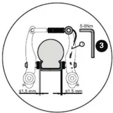
text_image
≤1.5 mm ≤1.5 mm 5-8Nm 3text_image
SW 15 mm SW 15 mmnatural_image
Technical diagram of a bicycle wheel assembly with labeled components and an arrow indicating rotation (no text or symbols beyond label)text_image
ca. 14 mmnatural_image
Line drawing of a device with a circular frame and textured grip, no text or symbols presenttext_image
A B C D E F ECongratulations on the purchase of this PUKY play bicycle. You have acquired a quality product, which is certain to bring great joy. This User Manual contains information regarding the assembly, safe operation and maintenance of this new bicycle. Should you have any questions or problems, please contact your dealer or contact us via our website: www.puky.de.
2. Parental responsibility
Risks during play are, for the most part, excluded when used in accordance with the intended purpose. However, please take into consideration that unforeseen situations and hazards may occur as a result of the natural need for movement and the temperament of young children and adolescents for which the manufacturer cannot be held liable. For this reason, instruct children and adolescents in the correct bicycle conduct whilst supervising them. At the same time, also draw their attention to potential dangers.
3. User notes
The play bicycle is not suitable for sporting activities (e.g. jumps). The bicycle may only be used on paved paths and roads without obstacles. The bicycle is not suitable for jumps, tricks or cross-country use.
When children are using the bicycle, it may not be ridden in the vicinity of stairs, slopes, steep terrain, swimming pools or other bodies of water. Stairs in the vicinity must be secured in such a way to prevent children from riding up or down them on their bicycle.
The play bicycle may only be used in suitable areas and away from public roads. The bicycle does not comply with the requirements of German Road Traffic Regulations (StVZO) and may not be used on public roads. The relevant applicable national legal requirements are to be observed.
The permissible total weight for this bike (bike + rider + baggage) is 60 kg.
The load that may be placed on the luggage rack will depend on the version of the rack (see the embossing on the rack). For road safety reasons, we do not recommend using the rack of a play vehicle for carrying loads. Only the serial installed racks may be used.
It is necessary to wear suitable clothing and closed shoes. PUKY recommends wearing a safety helmet (see PUKY Accessories).
The bicycle is not suitable for mounting a child seat. Pay attention to potential trap hazards when using and maintaining.
Play bicycle
Mount supporting wheels in a secure and form-fitting manner to the rear when required as a learning aid (to maintain balance). The use of support wheels is only permitted during the course of a brief learning period, since with increased practice the support wheels may apply uncontrolled forces to the frame.
Please pay attention to the reduced effect of the brakes on the front wheel when it is wet.
Sudden, forceful braking with the rim brake should be avoided since the behaviour of the vehicle may suddenly change as a result which may end in a fall.
On long slopes, long periods of braking with the back pedal brake are to be avoided (excess heat to the back pedal brake nave).
The valve caps must be firmly tightened and kept out of reach of children (risk of choking). Subsequent additions or modifications to the bicycle (especially the braking systems) will change the behaviour of the vehicle and may pose a risk.
4. Unpacking and scope of delivery
Do not use any sharp objects when opening the packaging and removing protective material. If you were to do so, you may damage the paint or parts of the bike.
Keep all packaging material out of reach of children.
- Remove all parts from the packaging.
- Remove the protective material.
- Examine the package for completeness and proper condition. If anything is missing, please contact your dealer before you continue to assemble the bike.
5. Assembly and first use
Prepare for use by adjusting to the height of the child. The saddle is to be set so that at least the toes, preferably the ball of the foot, reach the ground in order to ensure balance can be achieved when at a standstill. In doing so, the marking showing the minimum insertion depth on the saddle post into the frame tube must be observed. For more information, see below.
The handlebar, hand brake lever and bell must be easy for the child to reach from the set saddle position.
In doing so, the marking showing the minimum insertion depth of the handlebar shaft must be observed. After adjusting the handlebar, tighten the clamping screws firmly. Use the following safety checklist to check the bicycle before using.
When mounting the pedals, observe the right and left threads (labelled on the pedal axis with an R or L in the vicinity of the thread).
The images for the assembly instructions can be found on the last pages of this manual.
After assembly, please conduct a safety check in accordance with the safety checklist!
During assembly, please note that some parts, such as pedal thread and clamping cone are lubricated.
Assembly must be carried out with great caution and by an adult, to avoid any potential subsequent accidents or injuries. Please take your time when assembling the bike. In some cases, it is necessary to tighten screws with a prescribed torque. The torque value is stated in Newton metres (e.g. 2 Nm). If the torque with which a screw is tightened is too low, the connection may still be too loose and therefore unsafe. If the torque is too high, screws and other parts may be damaged or destroyed. Please contact your dealer or a workshop if you have any questions.
First remove the plastic protective caps from the cap nuts of the front and rear axle as well as from the cantilever brakes at the front. Also remove the plastic foil which has been used to protect the cranks.
Remove the handlebar padding from the handlebar and unscrew (with just a few rotations) the underlying screw at the stem with the aid of a 6 mm Allen key (YOUKE models) or a 13 mm spanner (STEEL/ STEEL-CLASSIC models). Now you can remove the plastic cover that protects the clamping cone at the lower end of the stem shaft.
6. Maintenance and care
If the handbrake lever can be pulled more than half-way to the handlebar before the braking effect takes place, the brake must be adjusted.
The braking surfaces must be clean, grease-free and the brake pads must be parallel to one another.
Worn pads must be replaced immediately! When replacing, make sure you use original pads or ensure that they match the material of the rim at least (e.g. see the label: "Alloy / Alu" for aluminium rims).
Caution in the event of rim wear
Regularly check the state of the rims and pay special attention to the wear groove which surrounds the rim. Consult your specialist workshop in good time (when the groove is almost worn away). Breakage and accident risks!
Pay special attention to ensure that the handlebar and saddle do not rotate!
Check the chain tension and adjust as necessary (if required, by loosening the rear wheel, aligning and tightening again).
12
GB


Pay attention to the correct air pressure (the prescribed pressure is indicated on the sides of the tyres). Do not repair damaged or deformed parts. Damaged or deformed parts must be replaced. Original replacement parts can be obtained from your PUKY dealer. Spare parts: Tyres (including tubes), rims, brake cable, brake pads, chain, chain rings, handle covers.
All maintenance work requires specialist knowledge and you should consult your dealer for advice. Interested children may 'supervise' but should not do the work themselves.
In case of a tire change, please visit us on our homepage at www.puky.de. There you will find the appropriate video instructions for a tyre change (YOUKE/ STEEL/ STEEL CLASSIC models with chain guard and LS-PRO 16 and LS-PRO18 models with Chainlooper chain guard).
Cleanliness and corrosion protection
All painted and metallic surfaces can be cleaned and protected using ordinary car care products. Only use environmentally friendly products and never use any aggressive detergents. Regularly oil the chain (chain or universal oil) and clean when necessary.
The flanks of the rims (braking surfaces) must be grease-free!
The vehicle is to be protected from winter salt and long periods of storage in damp spaces (e.g. garage) are to be avoided. If you do store the bicycle in a damp environment, protect the surfaces of unpainted metal parts (screws, nuts etc.) with a suitable surface seal (e.g. spray wax).
Hub and ball bearing should be checked from time to time by a specialist, adjusted and lubricated as required. The vehicle is to be protected from winter salt and long periods of storage in damp spaces (e.g. garage) are to be avoided.
Do not use a pressure washer/power washer to clean the vehicle.
- Statutory warranty
Statutory warranty covers defects. Damage resulting from improper use, use of force, lack of maintenance, or normal wear and tear, is excluded from such a statutory defect warranty.
Enjoy your travels!
Safety checklist
Saddle
Firmly secured and cannot be rotated (5-8 Nm) ^*
Minimum insertion depth marking observed
Balls of feet reach the ground

Handlebar
Minimum insertion depth observed
Handlebar shaft tube secured and cannot be rotated (15 Nm)*
Handlebar cannot be rotated

easy to reach, upright seating position

Handles cannot be rotated

Handbrakes
Brake lever secure (2 Nm), easily accessible
Functions perfectly

Brake pad clean, grease-free, positioned correctly
Back pedal brake
Function checked
Chain
Chain tension is OK ( play approximately 1.5 cm)
Chain guard is complete

Tyres
Sufficient profile
Sufficient air pressure (air pressure to be maintained is on the tyre)
Wheels
Aligned
Spokes evenly tightened

Axle nuts firmly tightened (VR 12 Nm, HR 10 Nm or 15 Nm)*
Pedals
Rotate easily
Firmly fitted without excess play

Bell
Clear ring, easily reached
Visual check
Components without fault and all attached parts, such as protective guards and luggage rack, sufficiently well secured.


(*Torques of screws in Newton metres)
GB
13


THE DELIVERY CONSISTS OF CHILDRENS'BICYCLE 12" - 18"
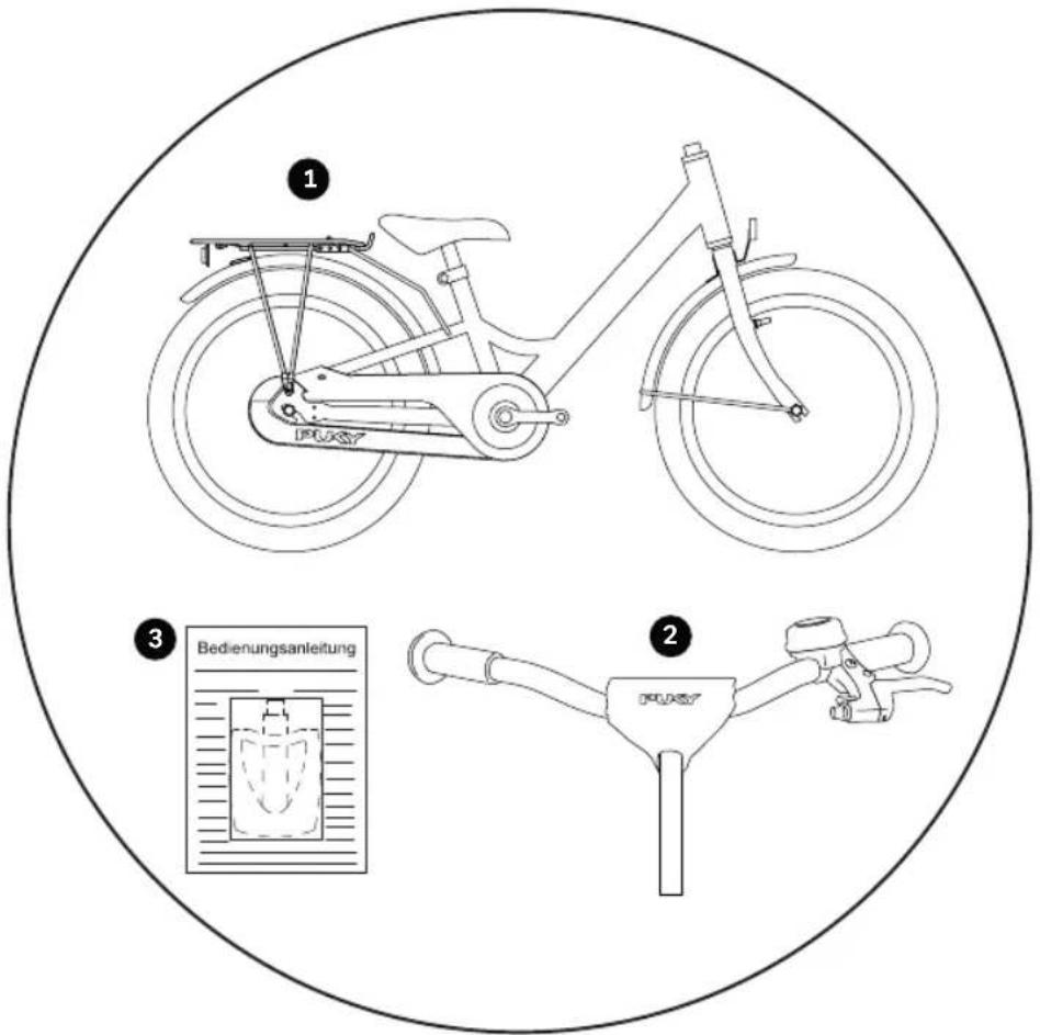
- Bike preassembled
- Handlebar preassembled
- Pedals and User Manual in a plastic bag, for 3-gear models: Additional gear stick
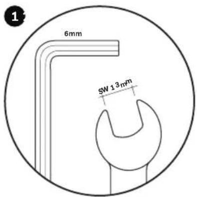
YOU WILL NEED THE FOLLOWING TOOLS FOR ASSEMBLY
The tools are not part of the scope of delivery.
text_image
6mm 5W 13mm- 6 mm Allen key (YOUKE models) or a 13 mm spanner (STEEL / STEEL CLASSIC models)

text_image
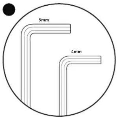
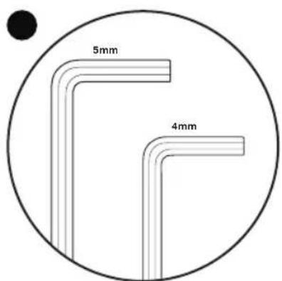
5mm 4mm- 4 mm and 5 mm Allen key (YOUKE, STEEL, STEEL CLASSIC models, CYKE 16, CYKE 18, CYKE 18-3, LS-PRO 16 and LS-PRO 18 models)
text_image
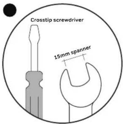
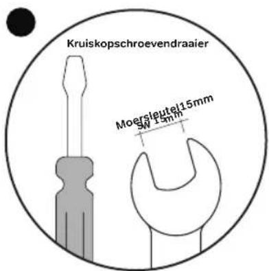
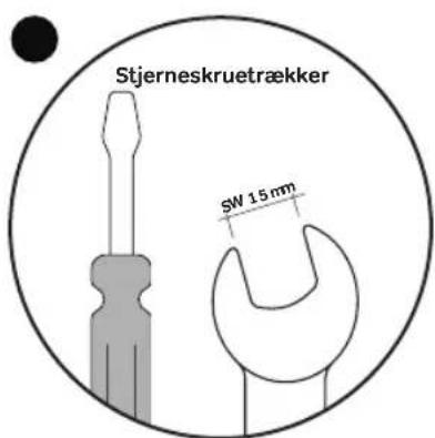
Crosstip screwdriver 15mm spanner- 15 mm spanner and Crosstip screwdriver
14
GB
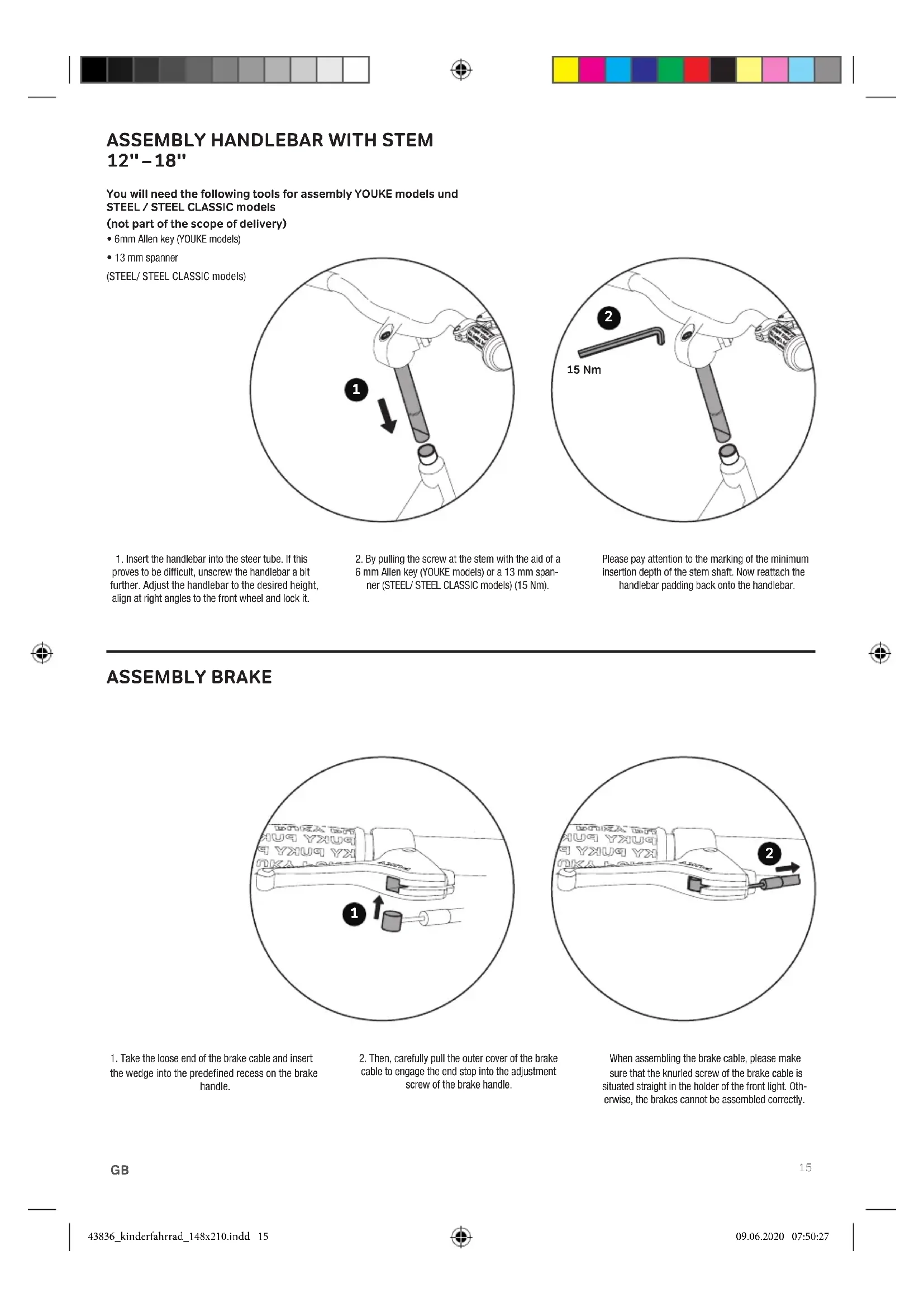
ASSEMBLY HANDLEBAR WITH STEM
12"-18"
You will need the following tools for assembly YOUKE models und STEEL / STEEL CLASSIC models
(not part of the scope of delivery)
- 6mm Allen key (YOUKE models)
- 13 mm spanner
(STEEL/ STEEL CLASSIC models)
text_image
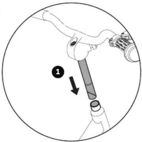
Diagram showing a mechanical device with labeled component '1' and directional arrow indicating motion or movement.- Insert the handlebar into the steer tube. If this proves to be difficult, unscrew the handlebar a bit further. Adjust the handlebar to the desired height, align at right angles to the front wheel and lock it.
- By pulling the screw at the stem with the aid of a 6 mm Allen key (YOUKE models) or a 13 mm spanner (STEEL/ STEEL CLASSIC models) (15 Nm).

text_image
15 NmPlease pay attention to the marking of the minimum insertion depth of the stem shaft. Now reattach the handlebar padding back onto the handlebar.

ASSEMBLY BRAKE
text_image
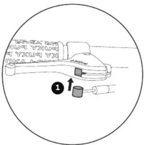
1- Take the loose end of the brake cable and insert the wedge into the predefined recess on the brake handle.
- Then, carefully pull the outer cover of the brake cable to engage the end stop into the adjustment screw of the brake handle.

text_image
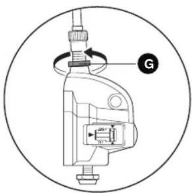
2 UHUA BHI YXUQ YXUQ YXUQ YX OKA LCKEWhen assembling the brake cable, please make sure that the knurled screw of the brake cable is situated straight in the holder of the front light. Otherwise, the brakes cannot be assembled correctly.
GB
15
SETTING AHEAD STEM
16" - 18"
The handlebar has been set at the factory to the highest position, thus, all spacers are located under the stem. If required, remove the stem and adjust the spacers to lower the handlebar height.
For adjusting the handlebar height for models with ahead stem you will need the following tools.
(The tools are not part of the scope of delivery.)
- 5 mm and 4 mm Allen key (CYKE und LS-PRO models)
text_image
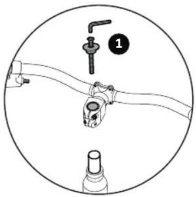
Diagram showing a mechanical assembly with labeled parts, including a lever and a bottle component.-
First undo and remove the ahead cap (5mm Allen key).
-
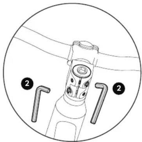
Then undo the two steerer tube clamping screws (4mm Allen key).
-
Now the stem can be removed from the steerer
text_image
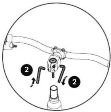
Diagram showing a mechanical assembly with numbered parts and directional arrows indicating motion or force directions.tube. Now set the handlebar height according to requirement. Possible positions are:
- All spacers located under the stem (highest handlebar position, set at the factory)
- Spacers over the stem and under
natural_image
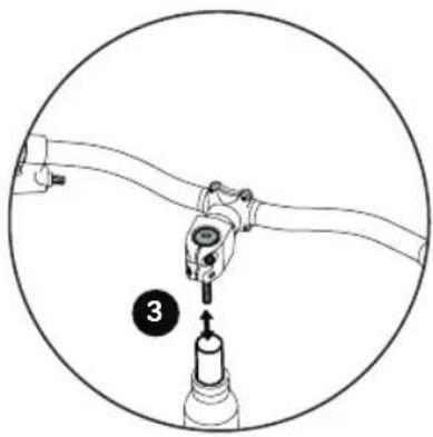
Diagram of a mechanical assembly with a numbered component (3) and a tool inserted into a cylindrical component, enclosed in a circle (no text or symbols)(medium handlebar position)
- All spacers above the stem (lowest handlebar position)
No spacers may be removed!
ASSEMBLY AHEAD STEM
16" - 18"
To assemble the ahead stem you will need the following tools.
(The tools are not part of the scope of delivery.)
- 5 mm and 4 mm Allen key
natural_image
Technical line drawing of a mechanical device with a lever and mounting holes, enclosed in a circular frame (no text or symbols)- After rearranging the spacers, fit the ahead cap again, align the handlebars to be straight in the direction of travel and set the play of the control bearing correctly. To do this, use the setting screw in the ahead cap
Correct setting: The handlebars must be easy to turn without play in the control bearing.
natural_image
Technical diagram of a mechanical device with two labeled parts (2), no readable text or symbols present.- Now tighten up the steerer tube clamping screws of the stem with the correct torque.
The torque for the clamping of the stem on the steerer tube shaft: 5-6 Nm. Make sure that the stem is firmly mounted to the steerer tube and cannot rotate.
GB
SETTING THE BRAKES: (V-BRAKE)
The bicycle has two calliper brakes. The left brake lever operates the brake on the front wheel, the right brake lever operates the brake on the rear wheel. Depending on the model, the bicycle may also have a back pedal brake for the rear wheel.
To set the brake you will need the following tools. (The tools are not part of the scope of delivery.)
• Crosstip screwdriver
text_image
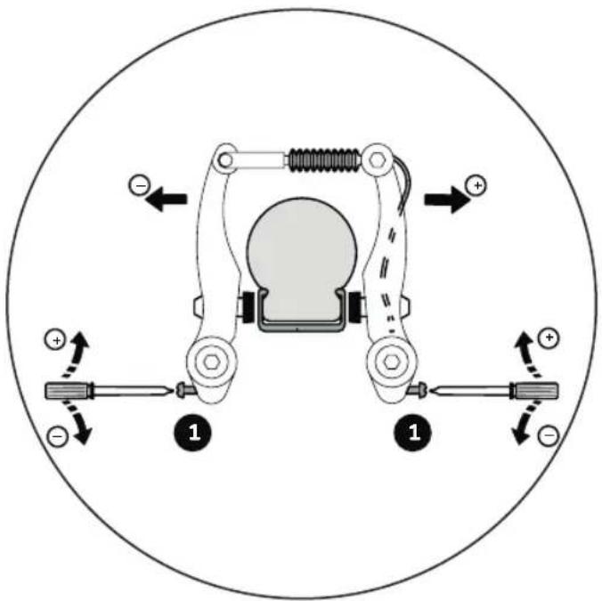
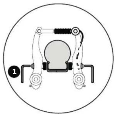
Diagram of a mechanical or electrical device with labeled components and directional arrows indicating motion or force directions.- Centre the brake arms by turning the adjusting screw.
The gap between the brake pad <-> rim should be identical on both right and left and the contact between brake pad/rim should be applied simultaneously on both sides when you brake.
You will need a cross-headed screwdriver. By turning the screw in, you move the appropriate brake arm away from the rim, turning the screw out moves the screw towards the rim.
It is important that the brake levers are actuated several times so that the tension of the brake arms is evenly distributed to both sides and the settings take effect.

To set the brake lever and tension you will need the following tools.
(The tools are not part of the scope of delivery.)
• Crosstip screwdriver
natural_image
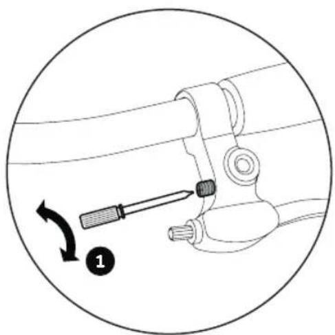
Diagram of a screwdriver inserted into a mechanical component, showing a curved arrow indicating rotation (no text or symbols present)- The handle distance (distance of brake lever to handlebar) can be adjusted individually using an cross-headed screwdriver on the brake handle. Please remember that braking must taken effect before the brake lever reaches the handlebar!
natural_image
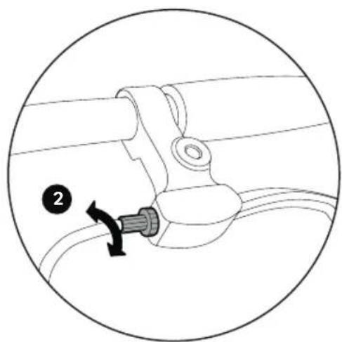
Diagram of a mechanical component with a numbered label (2) and directional arrow, no readable text or symbols present.- The tension can be set on the brake handle using the knurled screw.
The brake is set correctly if the brake pads are all approximately 1.5 mm from the rims.
GB
17
REPLACING THE BRAKE PADS
For replacing the brake pads you will need the following tools.
(The tools are not part of the scope of delivery.)
- 5 mm Allen key
natural_image
Mechanical device diagram with labeled parts, no readable text or symbols-
Undo the fastening nut of the brake pad using an Allen key sized 5 mm (1) and replace the brake pads.
-
This means that the brake pads should rest 1 mm
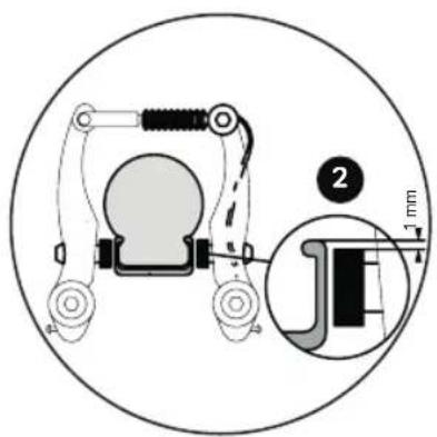
text_image
Technical diagram of a mechanical device with labeled parts and a magnified inset showing a 1 mm dimension detail.below the top edge of the rim. If these settings are not correct, loosen the fastening nut of the brake pad with a 5 mm Allen key and align as described above.
To do so, pull the brake lever and re-tighten the fastening nut (5-8 Nm).
- The tension is to be set so that the brake pads are
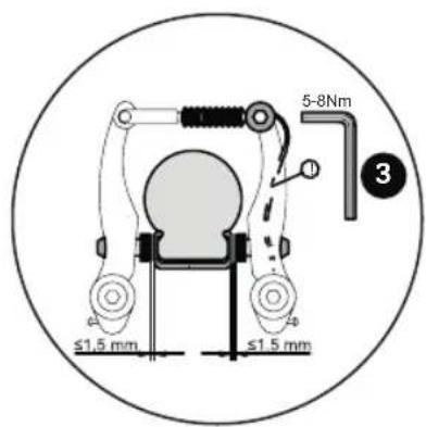
text_image
≤1.5 mm ≤1.5 mm 5-8Nm 3all approximately 1.5 mm from the rims. If subsequent adjustment is necessary, undo the tensioning screw and adjust the tension (tighten the tensioning screw back up using 6-8 Nm!) or carry out the step described in brake lever and tension step 2.
ASSEMBLY PEDALS
Please note that one pedal is equipped with a right-handed thread (for the right-handed driving direction) and the other pedal with a left-handed thread (for the left-handed direction).
To assemble the pedals you will need the following tools. (The tools are not part of the scope of delivery.)
- 15 mm spanner

text_image
L RThe pedals are labelled accordingly on the front face of the threaded axle with an "R" and an "L".
Screw the pedals with the aid of a 15 mm spanner to the cranks (20 Nm) – to do so, turn the Allen key on both sides in the direction of the front wheel.
18
GB
SETTING THE SEAT POSITION
Adjust the seating position so that the child is seated upright and a good overview is ensured. The handlebar, hand brake lever and bell must be easy for the child to reach.
To set the seat position you will need the following tools.
(The tools are not part of the scope of delivery.)
- 5 mm Allen key
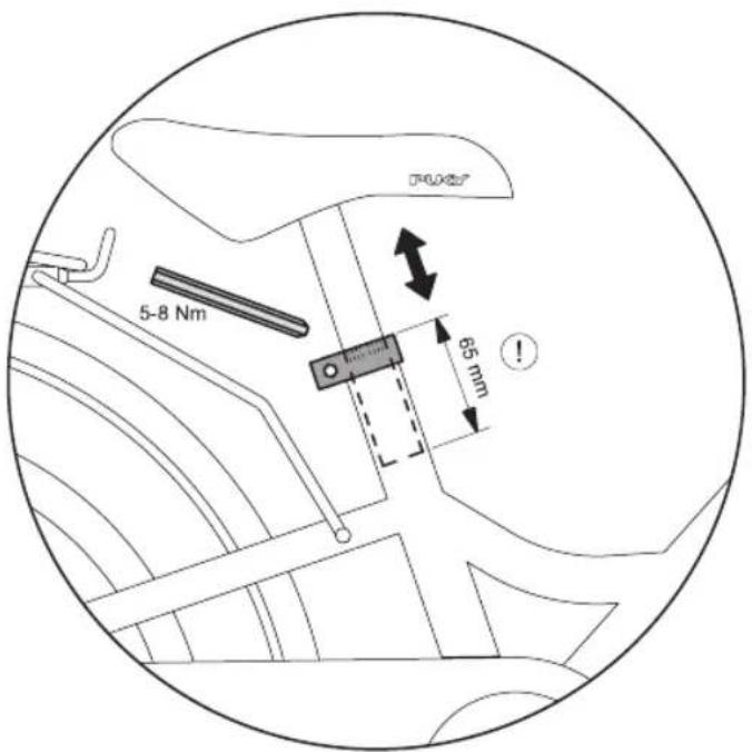
text_image
5-8 Nm 65 mm !Setting the height of the saddle: The saddle can be pulled out after releasing the saddle clamp with the aid of a 5mm Allen key. Set the saddle so that at least
the toes, preferably the ball of the foot, reach the ground in order to ensure balance can be achieved when at a standstill.
Please observe the following principles:
STEEL/-CLASSIC / YOUKE 12: 45 cm
STEEL/-CLASSIC / YOUKE 16: 49cm, CYKE 16: 48 cm / LS-PRO 16: 45 cm
STEEL/-CLASSIC / YOUKE 18: 53cm, CYKE 18: 51 cm / LS-PRO 18: 50 cm
Maximum height of the saddle:
The minimum insertion depth of the saddle post is 65 mm. There is an appropriate marking on the saddle post.
Then retighten the saddle clamp (torque 5-8 Nm).
GB
19
SETTING THE CHAIN TENSION YOUKE, STEEL UND STEEL CLASSIC
For setting the chain tension you will need the following tools. (The tools are not part of the scope of delivery.)
- 15 mm spanner
text_image
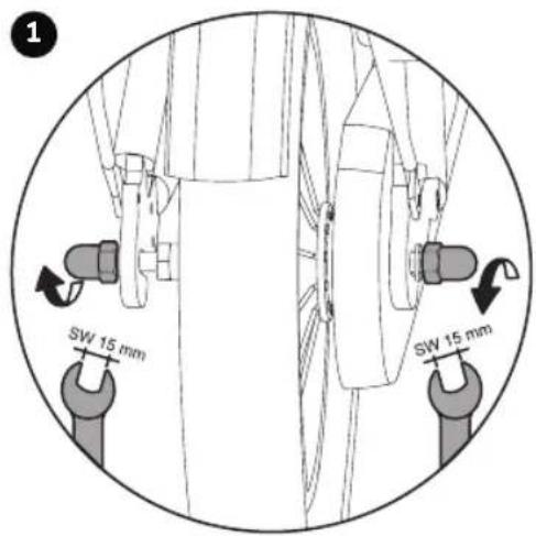
SW 15 mm SW 15 mmThe chain should have a vertical play of approximately 1.5 cm. The setting of the chain tension is carried out as follows:
1. Undo both wheel nuts of the rear wheel.
text_image
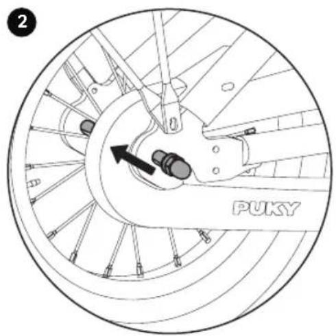
2 PUKY- Adjust the chain tension by sliding the rear wheel at the dropout. Then tighten the wheel nuts again (torque 15 Nm)
Tire change at www.puky.de
SETTING THE CHAIN TENSION LS-PRO 16 - LS-PRO 18 WITH CHAINLOOPER
For setting the chain tension you will need the following tools. (The tools are not part of the scope of delivery.)
- 5 mm Allen key
text_image
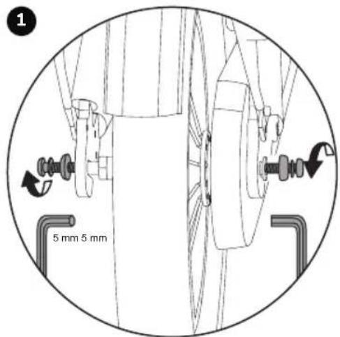
1 5 mm 5 mmThe chain should have a vertical play of approximately 1.5 cm. The setting of the chain tension is carried out as follows:
1. Undo both allen screws of the rear wheel
natural_image
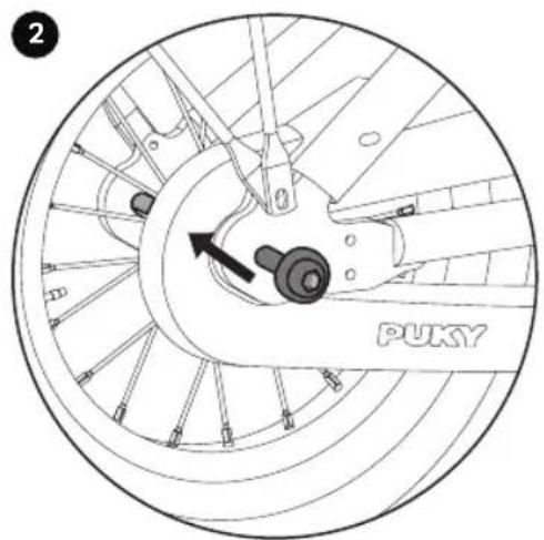
Technical diagram of a bicycle wheel assembly with labeled components and an arrow indicating rotation (no text or symbols beyond label)- Adjust the chain tension by sliding the rear wheel at the dropout. Then tighten the allen screws again (torque 10 Nm)
Tire change at www.puky.de
20
GB
INSTALLATION OF GEAR HUB
(only for 3-gear models)
To assemble the gear hub you will need the following tools.
(The tools are not part of the scope of delivery.)
- 5 mm Allen key
text_image
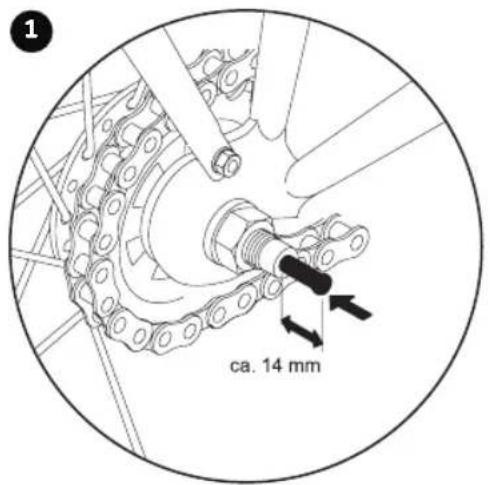
ca. 14 mm- Take the gear stick out of the plastic bag and insert it as far as it will go, along with the black spring, into the right side of the rear axle (in driving direction).
text_image
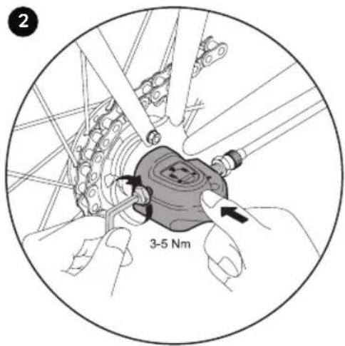
2 3-5 Nm- Then you can mount the gearbox onto the rear axle and tighten it with a 5 mm Allen key (3-5 Nm.) No further settings need to be made to the gearbox.

SETTING THE GEAR HUB
(only for 3-gear models)
To set the gear hub you will need the following tools. (The tools are not part of the scope of delivery.)
- 5 mm Allen key
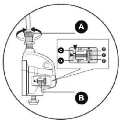
A1 Tension adjusting screw Red line em push rod Tension adjusting nut
B Push rod Yellow lines
C End of hub axis Yellow section of line F

Torque: 1.5 - 2.5 Nm
natural_image
Line drawing of a device with labeled sensor and body components, enclosed in a circular frame (no text or symbols)If renewed adjustment must be made during the course of product use, proceed as follows:
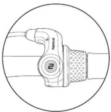
Switch the REVOSHIFT lever to 2. Then rotate the tension adjusting screw (A) in order to align the red line (D) on the push rod at the end (C) of the hub axis.
text_image
A B C D E F GDuring the setting process, check both yellow lines from above using the window. Rotate the crank and switch the REVOSHIFT lever from
3 to 1 and then back to 3. Repeat this process two or three times and check to make sure that the gears are changed. Switch the REVOSHIFT lever from 1 to 2 again and make sure that the red line on the push rod
text_image
G 25°at the end of the hub axis is aligned. If this is not the case, you must carry out the setting process again.
After setting switch unit IV secure the tension adjusting screw using the tension adjusting nut (G).
GB
21

1. Inleiding
text_image
6mm 5W 13mm- Inbussleutel 6mm (YOUKE-Modelle) of moersleutel 13 mm (STEEL / STEEL CLASSIC modellen)
text_image
5mm 4mm- Inbussleutel 4mm en 5 mm (YOUKE, STEEL, STEEL CLASSIC model, CYKE 16, CYKE 18, CYKE 18-3, LS-PRO 16 und LS-PRO 18 modellen)
text_image
GRIK X B YXU YXU Y YXU YX OKA L ① ↑
text_image
2 TOIKA BHI YUQ YXUQ E YXUQ YX OKA LUKAtext_image
Diagram showing a mechanical assembly with labeled parts, including a lever and a bottle component.text_image
Diagram showing a mechanical assembly with numbered parts and directional arrows indicating motion or force directions.natural_image
Diagram of a mechanical assembly with a numbered component (3) and no visible text or symbolsnatural_image
Technical diagram of a mechanical device with two labeled parts (2), no readable text or symbols present.text_image
Diagram of a mechanical or electrical device with labeled components and directional arrows indicating motion or force directions.natural_image
Diagram of a screwdriver inserted into a mechanical component, showing a curved arrow indicating rotation (no text or symbols present)natural_image
Diagram of a mechanical component with a numbered label (2) and directional arrow, no readable text or symbols present.natural_image
Mechanical device diagram with labeled parts, no text or symbols presentnatural_image
Mechanical device diagram showing a lever mechanism and a close-up of a mechanical component with a 1 mm dimension label (no text or symbols present)text_image
≤1.5 mm ≤1.5 mm 5-8Nm 3text_image
SW 15 mm SW 15 mmnatural_image
Technical diagram of a bicycle wheel assembly with labeled components (no readable text or symbols)text_image
ca. 14 mmnatural_image
Line drawing of a device with labeled sensor and body components, enclosed in a circular frame (no text or symbols)text_image
A B C D E F Gtext_image
Diagram showing a mechanical device with labeled component '1' and directional arrow, likely illustrating a step or motion process.
text_image
15 Nmtext_image
OKA YXU YXU YXU OKA ①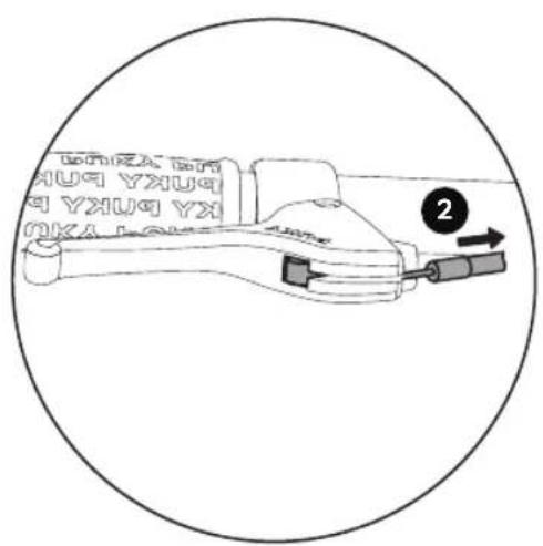
text_image
2 HUA YXUQ YXUQ YX OKA LOKEtext_image
Diagram showing a mechanical assembly with labeled parts, including a lever and a bottle component.text_image
Diagram showing a mechanical assembly with numbered parts and directional arrows indicating motion or force directions.natural_image
Diagram of a mechanical assembly with a numbered component (3) and no visible text or symbolsnatural_image
Technical line drawing of a mechanical device with a lever and labeled component (no text or symbols beyond label)natural_image
Technical diagram of a mechanical device with two labeled parts (2), showing internal components and wiring (no text or symbols beyond labels)text_image
Diagram of a mechanical or electrical device with labeled components and directional arrows indicating motion or force directions.natural_image
Diagram of a screwdriver inserted into a mechanical component, showing a curved arrow indicating rotation (no text or symbols present)natural_image
Diagram of a mechanical component with a numbered label (2) and directional arrow, no readable text or symbols present.natural_image
Mechanical device diagram with labeled parts, no readable text or symbolstext_image
Technical diagram of a mechanical device with labeled parts and a magnified inset showing a 1 mm dimension detail.text_image
≤1.5 mm ≤1.5 mm 5-8Nm 3text_image
SW 15 mm SW 15 mmtext_image
ca. 14 mmnatural_image
Line drawing of a device with labeled sensor and body components, enclosed in a circular frame (no text or symbols)text_image
A B C D E F Gtext_image
6mm 5W 13mm- 6 mm unbrakonøgle (YOUKE-modeller) eller SW 13 mm skruenøgle (STEEL/ STEEL-CLASSIC modeller)
text_image
5mm 4mm- 4 mm og 5 mm unbrakonøgle (YOUKE, STEEL, STEEL CLASSIC modeller, CYKE 16, CYKE 18, CYKE 18-3, LS-PRO 16 og LS-PRO 18 modeller)
text_image
OKA YXU YXU YXU OKA ①
text_image
2 YKU YXU YX YXU YX YKU YX YKU YXINDSTILLING AF STYRETS H∅JDE VED MODELLER MED SKAFT TIL FREMPIND
16 TOMMER- 18 TOMMER
text_image
Diagram showing a mechanical assembly with labeled parts, including a lever and a bottle component.text_image
Diagram showing a mechanical assembly with numbered parts and directional arrows indicating motion or force directions.natural_image
Diagram of a mechanical assembly with a numbered component (3) and no visible text or symbolsstyrposition)
- alle spacer over frempind (laveste styrposition)
natural_image
Technical line drawing of a mechanical device with a lever and labeled component (no text or symbols beyond label)natural_image
Technical diagram of a mechanical device with two labeled parts (2), no readable text or symbols present.text_image
Diagram of a mechanical or electrical device with labeled components and directional arrows indicating motion or force directions.natural_image
Diagram of a screwdriver inserted into a mechanical clamp, showing a curved arrow indicating rotation (no text or symbols present)natural_image
Diagram of a mechanical component with a numbered label (2) and directional arrow, no readable text or symbols present.natural_image
Mechanical device diagram with labeled parts, no readable text or symbolstext_image
Technical diagram of a mechanical device with labeled parts and a magnified inset showing a 1 mm dimension detail.text_image
5-8Nm ≤1.5 mm ≤1.5 mm 3text_image
SW 15 mm SW 15 mmnatural_image
Technical diagram of a bicycle wheel assembly with labeled components (no readable text or symbols)text_image
ca. 14 mmnatural_image
Line drawing of a device with labeled sensor and cable, enclosed in a circular frame (no text or symbols)text_image
A B C D E F Gtext_image
Technical diagram of a mechanical device with labeled component G and internal ports, showing rotational motion arrows.text_image
Diagram showing a mechanical device with labeled component '1' and directional arrow indicating motion or movement.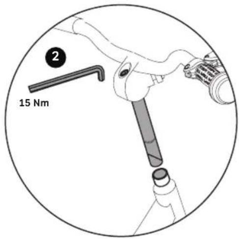
text_image
2 15 Nmtext_image
Diagram showing a mechanical assembly with labeled parts, including a lever and a bottle component.text_image
Diagram showing a mechanical assembly with numbered parts and directional arrows indicating motion or force directions.natural_image
Diagram of a mechanical assembly with a numbered component (3), no text or symbols presentnatural_image
Technical line drawing of a mechanical device with a lever and mounting holes, enclosed in a circular frame (no text or symbols)natural_image
Technical diagram of a mechanical device with two labeled parts (2), no readable text or symbols present.text_image
Diagram of a mechanical or electrical device with labeled components and directional arrows indicating motion or force directions.natural_image
Diagram of a screwdriver inserted into a mechanical clamp, showing a curved arrow indicating rotation (no text or symbols present)natural_image
Diagram of a mechanical component with a numbered label (2) and directional arrow, no readable text or symbols present.natural_image
Mechanical device diagram with labeled parts, no readable text or symbolstext_image
Technical diagram of a mechanical device with labeled parts and a magnified inset showing a 1 mm dimension detail.text_image
5-8Nm ≤1.5 mm ≤1.5 mm 3text_image
SW 15 mm SW 15 mmnatural_image
Diagram of a bicycle wheel assembly with a labeled component (PUKY) and directional arrow, no readable text or symbols beyond the label.text_image
ca. 14 mmnatural_image
Line drawing of a device with labeled sensor and head (no text or symbols beyond branding)text_image
A B C D E F Gtext_image
Technical diagram of a mechanical device with labeled component G and internal flow indicatorstext_image
6mm 5W 13mmtext_image
OKA YXU YXU YXU OKA ①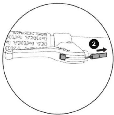
text_image
2 YKU YXU YX YXU YX YKU YX YKU YXtext_image
Diagram showing a mechanical assembly with labeled parts, including a lever and connector, enclosed in a circle.text_image
Diagram showing a mechanical assembly with labeled parts and directional arrows indicating motion or movement.natural_image
Diagram of a mechanical assembly with a numbered component (3) and no visible text or symbolsnatural_image
Technical line drawing of a mechanical device with a lever and labeled component (no text or symbols beyond labeling)natural_image
Technical diagram of a mechanical device with two labeled parts (2), no readable text or symbols present.text_image
Diagram of a mechanical or electrical device with labeled components and directional arrows indicating motion or force directions.natural_image
Diagram of a screwdriver inserted into a mechanical clamp, showing a circular motion indicator (no text or symbols)natural_image
Diagram of a mechanical component with a numbered label (2) and directional arrow, no readable text or symbols present.natural_image
Mechanical device diagram with labeled parts, no readable text or symbols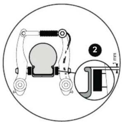
text_image
Technical diagram of a mechanical device with labeled parts and a magnified inset showing a 1 mm dimension detail.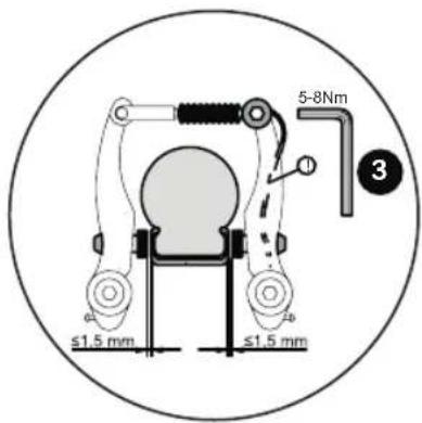
text_image
5-8Nm ≤1.5 mm ≤1.5 mm 3text_image
SW 15 mm SW 15 mmnatural_image
Technical diagram of a bicycle wheel assembly with labeled components (no readable text or symbols)text_image
ca. 14 mmnatural_image
Line drawing of a device with labeled sensor and body components, enclosed in a circular frame (no text or symbols)text_image
A C D E F E Btext_image
2 YXU YXU YXU YX OKA LOXtext_image
Diagram showing a mechanical assembly with labeled parts, including a lever and a bottle component.text_image
Diagram showing a mechanical assembly with numbered parts and directional arrows indicating motion or force directions.natural_image
Diagram of a mechanical assembly with a numbered component (3), no text or symbols presentnatural_image
Technical line drawing of a mechanical device with a lever and labeled component (no text or symbols beyond label)natural_image
Technical diagram of a mechanical device with two labeled parts (2), no readable text or symbols present.text_image
Diagram of a mechanical or electrical device with labeled components and directional arrows indicating motion or force directions.natural_image
Diagram of a screwdriver inserted into a mechanical component, showing a curved arrow indicating rotation (no text or symbols present)natural_image
Diagram of a mechanical component with a numbered label (2) and directional arrow, no readable text or symbols present.natural_image
Mechanical device diagram with labeled parts, no readable text or symbolstext_image
Technical diagram of a mechanical device with labeled parts and a magnified inset showing a 1 mm dimension detail.text_image
5-8Nm ≤1.5 mm ≤1.5 mm 3text_image
SW 15 mm SW 15 mmnatural_image
Technical line drawing of a bicycle wheel assembly with a PUKY component, showing no text or symbols.text_image
ca. 14 mmnatural_image
Line drawing of a device with labeled sensor and body components, enclosed in a circular frame (no text or symbols)text_image
A B C D E F Gtext_image
1 6mm 13mmtext_image
Diagram showing a mechanical assembly with labeled parts, including a lever and connector, enclosed in a circle.text_image
Diagram showing a mechanical assembly with labeled parts and directional arrows indicating motion or movement.natural_image
Diagram of a mechanical assembly with a numbered component (3) and no visible text or symbolsnatural_image
Technical line drawing of a mechanical device with a lever and mounting holes, enclosed in a circular frame (no text or symbols)natural_image
Technical diagram of a mechanical device with two labeled parts (2), no readable text or symbols present.text_image
Diagram of a mechanical or electrical device with labeled components and directional arrows indicating motion or force directions.natural_image
Diagram of a screwdriver inserted into a mechanical clamp, showing a curved arrow indicating rotation (no text or symbols present)natural_image
Diagram of a mechanical component with a numbered label (2) and directional arrow, no readable text or symbols present.natural_image
Mechanical device diagram with labeled parts, no readable text or symbolstext_image
Technical diagram of a mechanical device with labeled parts and a magnified inset showing a 1 mm measurement detail.text_image
5-8Nm ≤1.5 mm ≤1.5 mm 3text_image
SW 15 mm SW 15 mmnatural_image
Diagram of a bicycle wheel assembly with a labeled component 'PUKY' and directional arrow (no text or symbols beyond label)text_image
ca. 14 mmnatural_image
Technical line drawing of a device with labeled sensor and head (no text or symbols)text_image
A B C D E F Gtext_image
Technical diagram of a mechanical device with labeled component G and internal flow indicatorstext_image
6mm 5W 13mmtext_image
Diagram showing a mechanical device with labeled component '1' and directional arrow indicating motion or movement.text_image
Diagram showing a mechanical assembly with labeled parts, including a lever and a bottle component.text_image
Diagram showing a mechanical assembly with numbered parts and directional arrows indicating motion or force directions.ные положения:
natural_image
Diagram of a mechanical assembly with a numbered component (3) and no visible text or symbolsnatural_image
Technical diagram of a mechanical device with two labeled parts (2), no readable text or symbols present.text_image
Diagram of a mechanical or electrical device with labeled components and directional arrows indicating motion or force directions.natural_image
Diagram of a screwdriver inserted into a mechanical clamp, showing a curved arrow indicating rotation (no text or symbols present)natural_image
Diagram of a mechanical component with a numbered label (2) and directional arrow, no readable text or symbols present.natural_image
Mechanical device diagram with labeled parts, no readable text or symbols
text_image
Technical diagram of a mechanical device with labeled parts and a magnified inset showing a 1 mm dimension detail.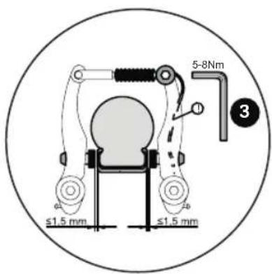
text_image
5-8Nm ≤1.5 mm ≤1.5 mm 3text_image
SW 15 mm SW 15 mmnatural_image
Technical line drawing of a bicycle wheel assembly with a labeled component (PUKY) and directional arrow, no readable text or symbols beyond the label.text_image
ca. 14 mmnatural_image
Line drawing of a device with labeled sensor and body components, enclosed in a circular frame (no text or symbols)text_image
A B C D E F GFrom September 01, 2016 (date of purchase), PUKY ^® is offering a 5-year guarantee for all vehicles on frames, forks and handlebars. The guarantee is transferable and can also be claimed in case of preparation and material errors by second or third-hand customers. In order to activate the guarantee for the first time, (online) registration by the purchaser is required within 4 weeks after purchase of the vehicle. You can obtain further information under: www.puky.de
NL
Please complete the identification plate on the cycle passport page.
The PUKY identification plate is fitted to the vehicles as shown in the drawings below and must be noted down for ordering replacement parts from your dealer.
natural_image
Technical line drawing of a car wheel assembly with brake calipers and suspension components (no text or symbols)Typenschild/Typens child/Identification plate/Typeplaatje/Plaque signalétique/Typeskilt/Targhetta/Oznakowanie produktu/
natural_image
Two colorful children's cycling helmets, one white with pink flower design and black stripes, the other blue with a red helmet featuring a cartoon character (no text or symbols visible)
natural_image
Green PUKY backpack with cartoon rabbit illustration (no text or symbols)

natural_image
Two colorful plastic hoses with white connectors, one blue and one green, arranged in a coiled pattern (no text or symbols visible)
natural_image
Pink and gray children's bicycle with a colorful flower bag (no visible text or symbols)
natural_image
Pink tricycle with black wheels and a colorful cargo basket (no text or symbols visible)
natural_image
Two PUKY-branded athletic gloves (black and blue) with green accents, shown against white background (no text or symbols visible)
natural_image
Illustration of a cartoon character with red hat and blue background, no readable text or symbols
natural_image
Pink triangular banner with a white unicorn, blue wings, and stars, topped with a red lantern (no text or symbols)


natural_image
Close-up of a black PUMPE tool with attached yellow cable, next to a black mechanical component (no visible text or symbols)
natural_image
Two PUKY winter sports gloves, one black and one gray, with a cartoon character on the helmet (no text or symbols visible)
natural_image
Red PUKY athletic helmet with black strap (no text or symbols visible)
natural_image
Red and black striped fabric with a black keypad inserted, no visible text or symbols


text_image
CRUSADER BUKY AND CHECK VAND MUCH MORE CHECK WWW.PUKY.DE

natural_image
Two PUKY wristcoats, one red and one olive-green, placed side by side (no text or symbols visible on the covers)
natural_image
Close-up of a red and black bicycle with visible tread pattern and wheel rim (no text or symbols)FAHRZEUGPASS/VEHICLE PASSPORT/VERVOERMIDDELPASJE CARTE D'IDENTIFICATION DE L'ENGIN/IDENTIFIKATIONSKORT LIBRETTO DEL VEICOLO/DOKUMENT PRODUKTU/PRUKAZ MAJITELE PERMISO DE CIRCULACIÓN/ПАСПОРТ ТРАНСПОРТНОГО СРЕДСТВА
Name/Surname/Naam/Nom/Efternavn/Cognome/Nazwisko/Jméno/Apellido(s)/Фамилия
Vorname/First name/Voornaam/Prénom/Fornavn/Nome/Imię/Přijmení/Nombre/Имя
Straße/Street/Straat/Rue/Gade/Via/Ulica/Město/Vía/Yлицa
D-42489 Wülfrath, Germany