STWM722C - Microphone Skytec - Free user manual and instructions
Find the device manual for free STWM722C Skytec in PDF.
| Product type | UHF wireless microphone system |
| Brand and model | Skytec STWM722C |
| Category | Microphone |
| Frequency band | 863 - 865 MHz |
| Maximum range | 50 m (normal conditions) |
| Audio frequency response | 50 Hz - 15 kHz, ±3 dB |
| Total harmonic distortion | < 1% |
| Signal-to-noise ratio (receiver) | > 85 dB |
| Channel rejection | > 70 dB |
| Spurious frequency rejection | > 70 dB |
| Reception sensitivity | -105 dBm |
| Audio output level | 0 dB ±300 mV |
| Receiver power supply | 230 VAC via mains adapter, 13-15V DC 300 mA |
| Handheld microphone power supply | 2 x 1.5V R6 batteries |
| Bodypack transmitter power supply | 2 x 1.5V R6 batteries |
| Receiver output connectors | Balanced XLR and unbalanced 6.35mm jack |
| Bodypack transmitter input connector | 3.5mm jack for lavalier/headset microphone |
| Receiver dimensions | 175 x 135 x 43 mm |
| Handheld microphone dimensions | 238 x ø50 mm |
| Bodypack transmitter dimensions | 100 x 65 x 30 mm |
| Operating temperature | -29°C to 74°C |
| Use | Indoor use only |
| Maintenance | Clean with a dry cloth, do not use any liquid |
| Safety | Keep out of reach of children, do not open, unplug during storms |
Frequently Asked Questions - STWM722C Skytec
User questions about STWM722C Skytec
0 question about this device. Answer the ones you know or ask your own.
Ask a new question about this device
Download the instructions for your Microphone in PDF format for free! Find your manual STWM722C - Skytec and take your electronic device back in hand. On this page are published all the documents necessary for the use of your device. STWM722C by Skytec.
USER MANUAL STWM722C Skytec
text_image
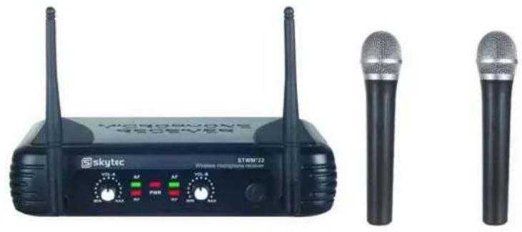
MICROPHONE RECEIVER SKYTEC STWM722 Wireless microphone receiver VOL-A AF AF VOL-B MIN MAX RF PWR RF MIN MAXnatural_image
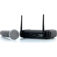
Product photo of a Skytec wireless router with external microphone and control panel (no visible text or symbols)STWM722 2CH RECEIVER (179.170)
natural_image
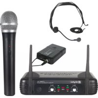
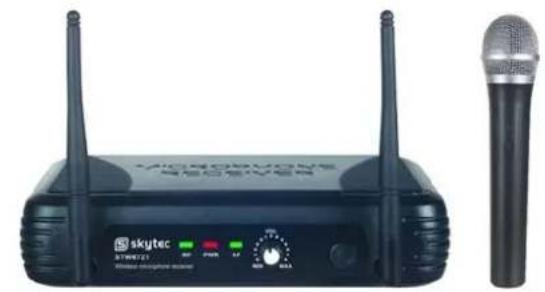
Two black wireless devices labeled 'SKYTEC' with two antennas and two separate microphones (no visible text or symbols on the devices themselves)STWM721 1CH DIVERSITY RECEIVER (179.175)
natural_image
Black wireless router with two antennas and a microphone, no visible text or symbols on the device body.ACCESSORIES:
natural_image
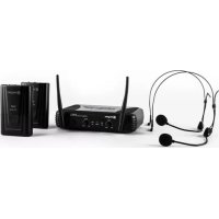
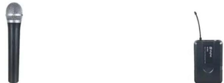
Two black audio devices: a microphone and a wireless device (no visible text or symbols)STM4 HANDHELD MICROPHONE PDB3 BODYPACK (179.166 / 179.167) (179.168 / 179.169)
natural_image
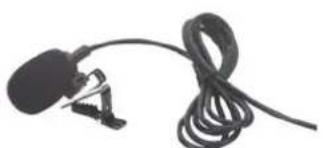
Close-up of a black plastic microphone with coiled cable, no visible text or symbolsPDT3 TIE CLIP MICROPHONE (179.158)

natural_image
Black headset with earbuds and antenna (no visible text or symbols)PDH3 HEADSET (179.156)
UK
Thank you very much for purchasing this SkyTec wireless microphone kit. Please read this manual thoroughly before using this equipment
Warning
- Always read the manual before using the product.
- Keep the manual so every new user can read it before using the product.
- Always keep the packaging. When a malfunction occurs, please send it in the original packaging.
- Only for indoor use. Do not use in moistures places.
- Don't expose to direct sunlight or heat sources.
- Don't let small objects or fluids enter the housing. This may cause malfunction.
- Clean this unit with a dry cloth. Don't use cleaning fluids or solvent.
- Unit contains no serviceable parts. Only the replacement parts named in this manual can be changed by the user or servicing personnel.
- Never open the unit, service may only be done by qualified personnel.
- Never remove or place the mains plug in a socket with wet hands.
- Disconnect the unit from mains power before servicing.
- Condensation water can form while reusing, please let the unit reach the environmental temperature before using it.
- Keep out of children's reach.
- When the unit is damaged in a way that internal parts are visible. NEVER connect the unit to a mains socket and NEVER switch the unit on. In this case, contact your supplier.
- When a lightning storm occurs, always disconnect this unit from the mains socket. Do the same when the unit won't or hasn't be used for a long period of time.
- Using this unit might cause disturbance in insufficiently shielded equipment. This disturbance might cause damage or accidents. Please check if there is any sensitive equipment in close proximity of the unit before installing it.
To all residents of the European Union
Important environmental information about this product.

This symbol on the device or the package indicates that disposal of the device after its lifecycle could harm the environment. Do not dispose the unit or batteries as unsorted municipal waste, its should be taken to a specialized company or local recycling service. If in doubt, contact your local waste disposal authorities.
SYSTEM FEATURES
All UHF Series systems offer a variety of exceptional features, including:
- Multiple System Use: Up to several UHF systems can be used in the same performance space. Each system must be set at a different frequency. (Frequency marked on the back of the receiver)
-
Simultaneous Output Use: Unbalanced 6.3mm phone plug and balanced XLR output connectors may be used simultaneously to different external devices.
-
Range: UHF Series transmitters will work at a distance of up to 50 meters from the receiver.
-
Noise Squelch: Squelch circuit analyzes signal strength and quality so that can reduce the likelihood of noise burst due to environmental RF (radio frequency) noise.
-
Low Battery Warning Light: A red light on the body-pack and hand -held transmitters warns the user that there is less than one hour of battery life left.
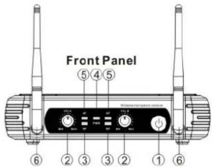
RECEIVER FEATURES
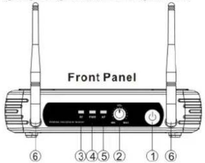
SINGLE CHANNEL RECEIVER
text_image
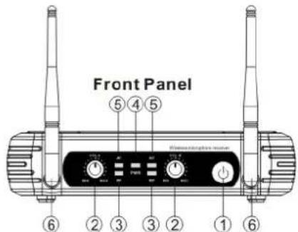
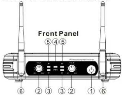
Front Panel ⑥ ③ ④ ⑤ ② ① ⑥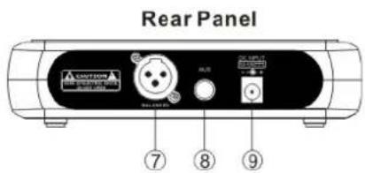
text_image
Rear Panel A CNTON A B R U B L U U U U ⑦ ⑧ ⑨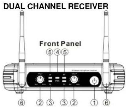
text_image
DUAL CHANNEL RECEIVER Front Panel ⑤ ④ ⑤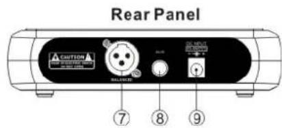
text_image
Rear Panel CAUTION BALANCED ON MOUNT ON MOUNT ON MOUNT 7 8 9- Power Switch: Power ON/OFF the receiver.
- Volume Knob: Adjust the volume output of receiver.
- "RF" signal-Indicator:Itis glows when the Receiver receive RF signal from Transmitter.
- Power Indicator: Indicate the power ON/OFF.
- "AF"Audio Level Indicator: Indicate the wireless system audio signal level.
- Antenna A/B.
- XLR Balanced Output Jack: Connect the audio cable from this jack to the input port of amplifier, mixer.
- 6.3mm Audio Output Jack: Connect the audio cable from this jack to the input port of amplifier, mixer.
- Power Jack: Connect the AC/DC adapter to receiver.
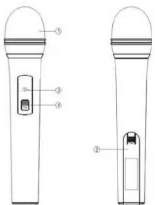
MICROPHONE-TRANSMITTER FEATURES
text_image
Technical diagram of two handheld devices with labeled parts, showing front and side views with numbered labels.-
Grille: Protects the cartridge and help reducing the breath sounds and wind noise.
-
Battery Cover: Open it to install the battery.
-
Low Battery Indicator: Red light glows when it is lack of power and should Renew the battery.
-
Power and Audio Mute Switch.
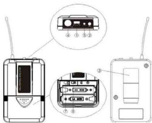
BODY-PACK TRANSMITIER FEATURES
text_image
Diagram of an wireless device showing front, side, and internal components with labeled parts-
Power and Audio Mute Switch.
-
Antenna: Transmit the RF signal of transmitter.
-
Bell Clip: Allach the transmitter to the belt.
-
Audio Input Jack: it is suitable for lavaliere system/headset system.
-
Low Battery Indicator: Red light glows when it is lack of power and should renew the battery.
-
State Setting Switch: Set the using slate of lavaliere system (L) / headset system(H).
-
Gain Adjusting Volume: Adjust the transmitter audio input gain.
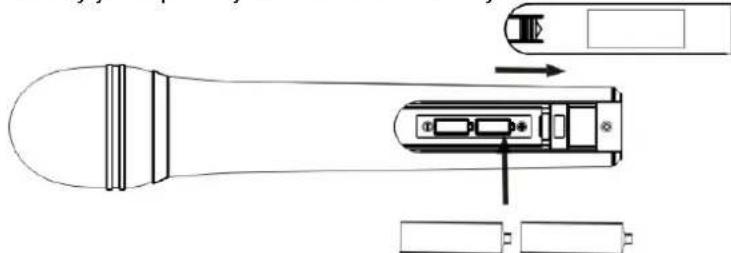
TRANSMITTER BATTERY INSTALLATION
- Battery Installation of Handheld Microphone: Push open the battery cover, Insert the supplied batteries into battery jar in polarity and cover the battery Cover.
natural_image
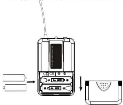
Technical line drawing of a handheld device with internal components and battery terminals (no text or symbols)- Battery Installation of Body pack transmitter: Push open the battery cover, Insert the supplied batteries into battery jar in polarity and close the battery cover.
text_image
Diagram showing battery connection to a mobile phone with AA 802 interface, followed by a close-up of the device's front panel.BODYPACK TRANSMITTER CONNECTION
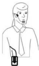
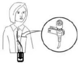
- Lavaliere Microphone Connection: Connect the connector of supplied. Lavaliere microphone to the connecting jack of transmitter (Shown as below) Set the transmitter work state in wireless lavaliere system.
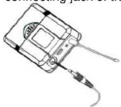
natural_image
Line drawing of a handheld electronic device with a cable and connector (no text or symbols)(a)
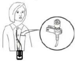
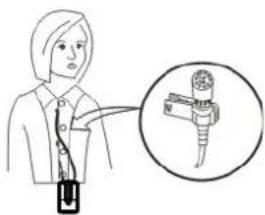
text_image
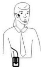
Illustration showing a person holding a device with an inset magnified view of a device labeled 'N' (no text or symbols on the device itself)(b)
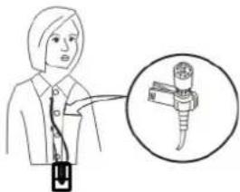
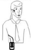
- Headset Microphone Connection: Connect the connector of supplied Headset microphone to the connecting jack of transmitter(Shown as below) Set the transmitter work state in wireless head set system.
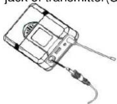
natural_image
Line drawing of a handheld electronic device with a cable and connector (no text or symbols)(a)

(b)
SYSTEM CONNECTION
- Receiver Power Connection: Connect the DC connector of supplied AC/DC adapter into the DC power input of receiver. Plug the AC input connector into an 230\~240VAC/50Hz outlet. (Shown as below)
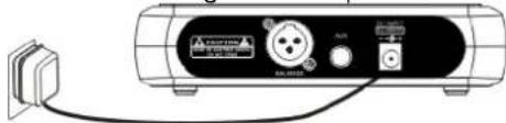
natural_image
Line drawing of a portable electronic device with ports and cables (no text or symbols)- Antenna: Keep the position of antenna at a 45 angle from vertical, .(Shown as below)
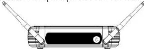
natural_image
Technical line drawing of a mechanical device with two protruding rods and a central button (no text or symbols)- Audio Connection: Connect the corresponding output of receiver by supplied 6.3mm phone jack audio cable or your XLR cable to the input of power amplifier, mixer.
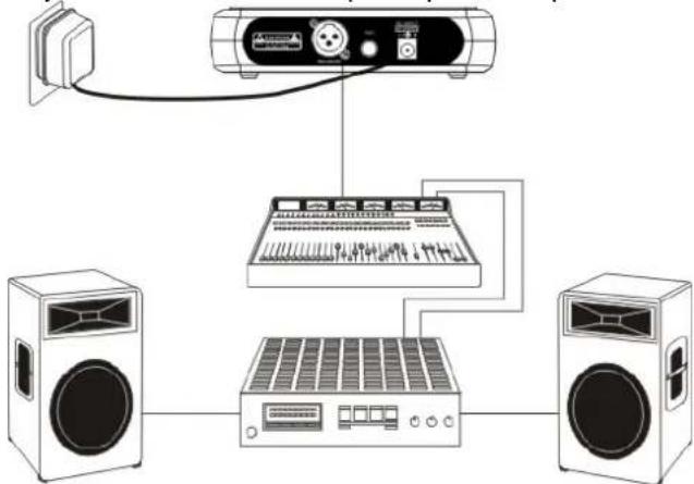
flowchart
graph TD
    A["Speaker"] --> B["Audio System"]
    B --> C["Speaker"]
    B --> D["Audio"]
BODYPACK TRANSMITTER AUDIO GAIN ADJUSTMENT
The audio gain control on transmitter has been factory-at the mid-range position for best performance in most applications. This may be necessary for soft singers or talkers, or guitar or basses with low outputs.
- To Increase Gain: Rotate the transmitter gain control clockwise with the screwdriver to increase audio gain.
- To Reduce Gain: Rotate the transmitter gain control counter clockwise with the screwdriver to reduce audio gain.
• To return audio gain to the factory setting, rotate the transmitter audio gain control to the mid position
TIPS FOR ACHIEVING MAXIMUM PERFORMANCE
- Make sure you can always see a receiver antenna from the transmitter position.
- Keep the distance from transmitter to receiver antenna as short as possible.
- Point receiver antennas away from each other at a 45 angle from vertical.
- Avoid placing the receiver antennas near metal surfaces and obstruction.
- Monitor battery fuel gauge and replace battery as soon as red light is on.
- If stacking or rack mounting receivers In a multiple-system use situation, do not allow antennas to touch or cross.
- Perform a walk-through before Performance or Presentation. If dead spots are found, adjust location of receiver. If dead sports remain, mark spots and avoid.
TROUBLESHOOTING
| PROBLEM | INDICATOR STATUS SOLUTION | |
| No sound | Red transmitter indicator is not flash | Slide transmitter POWER ON/OFF switch to ONMake sure battery is Inserted properly, observing battery (+/.). If battery is insertedproperly. replace with fresh battery. |
| No sound Red transmitter indicator Is flash Slide transmitter MUTE/ON switch to ON position | ||
| No sound Red receiver POWER light off. | Make sure ac adapter is securely plugged into electrical outlet and into de input connector. Make sure ac electrical outlet works and supplies proper voltage. | |
| No sound | Receiver signal Indicators A/B lights glowing | Turn up receiver volume control. Confirm that the output connections from the receiver to the external equipment are secure. |
| No sound | Receiver signal Indicators A/B lights off, Transmitter and receiver POWER lights glowing | Confirm transmitter's and receiver's frequencies match.Move transmitter closer to receiver |
| Sound level differs from level of a cabled instrument | Receiver signal Indicators A/B lights glowing | Adjust transmitter gain level to compessaryAdjust receiver volume as necessary |
| Sound level differs with different guitars | Receiver signal Indicators A/B lights glowing | Readjust transmitter gain level to compensate for differences In guitar outputs |
| Distortion level increases gradually | Receiver Signal Indicators A/B Lights and transmitter LOW BATTERY light glowing | Replace transmitter battery |
| Bursts Of noise or other audible radio signals present | Signal Indicators A/B lights on | Identify potential sources of interference (other RF·sources) and turn off, remove or use a wireless system operating on a different frequency |
| Momentary loss of sound as transmitter is moved around. performing area. | Receiver signal Indicators A/B lights off when sound is lost | Reposition receiver and perform walkthrough test, if audim dropouts persist mark "dead" spots and avoid them during performance |
SYSTEM SPECIFICATIONS
RF Carrier Frequency Range 863 to 865 MHz
(Available freq. depend on applicable regulations in country where system is used).
Operating Range.... 50m (under typical conditions)
Audio Frequency Response 50Hz to 15kHz,±3dB
THD....<1%
Operation temp. range -29°C to 74°C
NOTE:Battery characteristics may limit this
RECEIVER:
Power Requirements 230VAC adaptor
Power Requirements 13-15V DC nominal. 300mA
Signal/Noise Ratio ....>85dB
Border Upon Channel Rejection....>70dB
Image & Spurious Rejection ....>70dB
Audio Output Level: 0dB +/-300mV
Receiving Sensitivity -105dBm
Dimensions 175 x 135 x 43mm
HAND-HELD TRANSMITTER:
Power Requirements 2x 1.5V AA battery
Nominal Current Drain .... <40mA
Modulation Type FM
RF Output ....>10dBm
Max Deviation .... ±30kHz
Spurious Emission ....>55dB
Dimensions 238 x ø50mm
BODY-PACK TRANSMITTER:
Power Requirements 2x 1.5V AA battery
Nominal Current Drain .... <40mA
Modulation Type .... <FM
RF Output ....>10dBm
Max Deviation ....±30KHz
Spurious Emission ....>55dB
Dimensions 100 x 65 x 30mm
No license required (excluding geographical restrictions)
| BE | DK | F | FI | |
| HU | IT | NL | NO | PL |
| PT | RO | SI | ES | SE |
| CH | GB | |||
DE
Belgium (BE), Denmark (DK), France (F), Finland (FI), Germany (DE), Hungary (HU), Italy (IT), Netherlands (NL), Norway (NO), Poland (PL), Portugal (PT), Romania (RO), Slovenia (SI), Spain (ES), Sweden (SE), Switzerland (CH), United Kingdom (GB)

Please contact your radio licensing authority in your country, who will advise you on the available frequencies and transmitter power requirements.
NL
text_image
Front Panel ⑥ ③ ④ ⑤ ② ① ⑥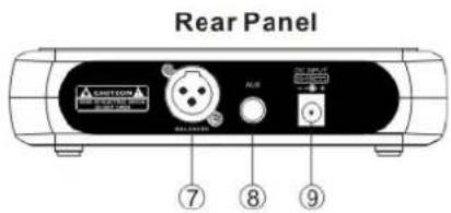
text_image
Rear Panel A210000 ALB ALB ⑦ ⑧ ⑨2-KANAALS ONTVANGER
text_image
Front Panel ⑤④⑤ Wiring/Relief/Relief module ⑥②③②①⑥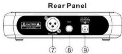
text_image
Rear Panel CANTON BEET BALUO FLUX EX-INPUT SUPPORT ⑦ ⑧ ⑨text_image
Technical diagram of a handheld device with labeled parts including a control panel and batterytext_image
Diagram of an wireless device with labeled components including a CD, audio jack, and external portsnatural_image
Technical line drawing of a handheld device with internal components and battery terminals (no text or symbols)
text_image
Diagram showing the internal structure of a mobile phone with battery, antenna, and display panel, including a close-up view of the device's front panel.BODYPACK AANSLUITINGEN
natural_image
Line drawing of a handheld electronic device with a cable and antenna (no text or symbols)(a)
text_image
Illustration showing a person pointing to a device with a magnified view of the device inside a circle.(b)
natural_image
Line drawing of a handheld electronic device with a cable and antenna (no text or symbols)(a)
(b)
SYSTEEM AANSLUITINGEN
natural_image
Illustration of a connected electronic device with ports and cables (no visible text or symbols)natural_image
Technical line drawing of a mechanical device with two protruding rods and a central button (no text or symbols)text_image
Front Panel ⑥ ③ ④ ⑤ ② ① ⑥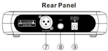
text_image
Rear Panel A CNTON BALANCE 7 8 9DUAL KANAL EMPFÄNGER
text_image
Front Panel 6 ⑤ ④ ⑤ Front/Right/Right button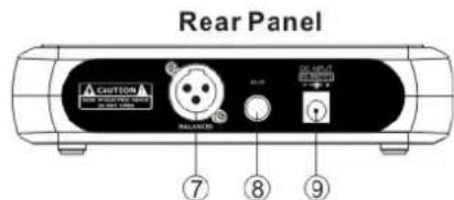
text_image
Rear Panel CUSTOM BALANCED 7 8 9text_image
Technical diagram of a handheld device with labeled parts including a control panel and a device inside a casing.text_image
Diagram of a mobile phone receiver with labeled components including audio jack, display, and control panelnatural_image
Technical line drawing of a handheld device with internal components and battery terminals (no text or symbols)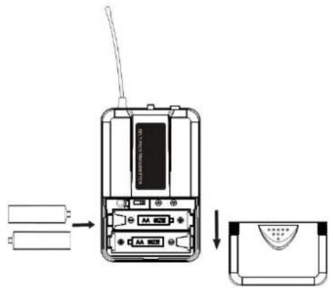
text_image
Diagram showing the internal structure of a mobile phone with battery, antenna, and display panel, including a close-up view.natural_image
Line drawing of a handheld electronic device with a cable and connector (no text or symbols)(a)
text_image
Diagram showing a person holding a device with an inset image of a mechanical component, possibly illustrating a device or tool concept.(b)
natural_image
Line drawing of a handheld electronic device with a cable and sensor (no text or symbols)(a)
(b)
SYSTEM ANSCHLÜSSE
natural_image
Illustration of a portable electronic device with ports and connectors (no visible text or symbols)natural_image
Diagram of a rectangular electronic device with two leads and a central button (no text or symbols)45° Winkel
Max Deviation .... ±30kHz
Modulation ...... FM
Max Deviation ....±30KHz
text_image
Front Panel ⑥ ③ ④ ⑤ ② ① ⑥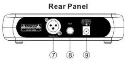
text_image
Rear Panel A250001 7 8 9RECEPTEUR DEUX CANAUX
text_image
Front Panel ⑤ ④ ⑤ Wires connected to the back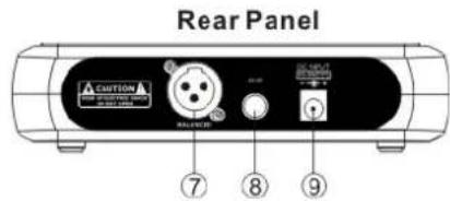
text_image
Rear Panel ACUTION AC-OUTPUT CONTROL RELAYER 7 8 9text_image
Technical diagram of two handheld devices with labeled parts, showing front and side views with numbered labels.text_image
Diagram of a mobile phone receiver with labeled components including front panel, rear panel, and internal display areas.natural_image
Technical line drawing of a handheld device with internal components and battery terminals (no text or symbols)text_image
Diagram showing battery connection to an electronic device with labeled ports and a close-up view of the component.BRANCHEMENTS EMETTEURS DE POCHE
natural_image
Line drawing of a handheld electronic device with a cable and connector (no text or symbols)(a)
text_image
Illustration showing a person holding a device with an inset image of a microphone labeled 'M' pointing to it.(b)
natural_image
Line drawing of a handheld electronic device with a cable and sensor attached (no text or symbols)(a)
(b)
BRANCHEMENT SYSTEME
natural_image
Technical line drawing of a rectangular electronic device with two leads and a central button (no text or symbols)natural_image
Blue glossy circular icon with a stylized white 't' symbol (no text or numbers)tronios
Sound & Light
CE Declaration of Conformity
Manufacturer:
Tronios
B.V.
Product Description: STWM-Series UHF Wireless Microphone System
Trade
Name:
SKYTEC
I hereby declare that the product meets the requirements stated in Directives:
LVD 2014/35/EU
■ EMC 2014/30/EU
■ RoHS 2011/65/EU
■ RED 2014/53/EU
Almelo,
19-09-2018
Name : M. Velders
Signature :

text_image
91Specifications and design are subject to change without prior notice..
www.tronios.com
Copyright © 2018 by TRONIOS the Netherlands