TSE Home 4001 - Lock Burg Wächter - Free user manual and instructions
Find the device manual for free TSE Home 4001 Burg Wächter in PDF.
| Product type | Electronic code lock (electronic cylinder) |
| Brand | Burg Wächter |
| Model | TSE Home 4001 |
| Keyboard power supply | 2 alkaline batteries LR6/AA (MIGNON) |
| Cylinder power supply | 2 alkaline batteries LR03/AAA (MICRO) |
| Opening code | 6 digits (administrator and user) |
| Number of E-KEY remote controls | 5 maximum |
| Communication range | 10 m maximum between keyboard and cylinder |
| Radio channels | 12 channels (factory setting channel 1) |
| Max. door thickness | 120 mm (60/60 mm measured from the middle of the fixing screw) |
| Operating temperature | -15°C to +50°C |
| Allowable humidity | Up to 95% (without condensation) |
| Blocking after incorrect codes | 1 min after 3 wrong entries, then 3 min after each subsequent error |
| Light indicators | Opening right (green), refusal (red), blocking (flashing red), programming mode (Prog), battery change, service call |
| Entering programming mode | Press ON, type 76, then Enter, then administrator code |
| Installation | Without drilling or cables, on any door with a profile cylinder bore |
| Maintenance | Change the batteries as soon as the change symbol lights up; do not grease or oil the lock |
| Spare parts | Alkaline batteries LR6/AA and LR03/AAA, optional remote control TSE 5103 E-KEY |
| Compliance | Directives 2014/53/EU (RED), 2014/30/EU (EMC), 2011/65/EU (RoHS) |
| General information | User manual available in multiple languages; declaration of conformity at www.burg.biz |
Frequently Asked Questions - TSE Home 4001 Burg Wächter
User questions about TSE Home 4001 Burg Wächter
0 question about this device. Answer the ones you know or ask your own.
Ask a new question about this device
Download the instructions for your Lock in PDF format for free! Find your manual TSE Home 4001 - Burg Wächter and take your electronic device back in hand. On this page are published all the documents necessary for the use of your device. TSE Home 4001 by Burg Wächter.
USER MANUAL TSE Home 4001 Burg Wächter
text_image
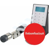
Code ✓ Prog Code X F G H IAbbildung
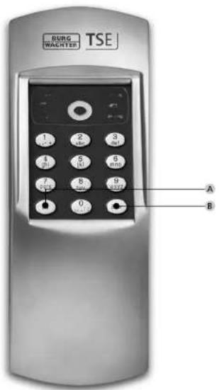
A On-Taste
B Enter-Taste
natural_image
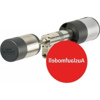
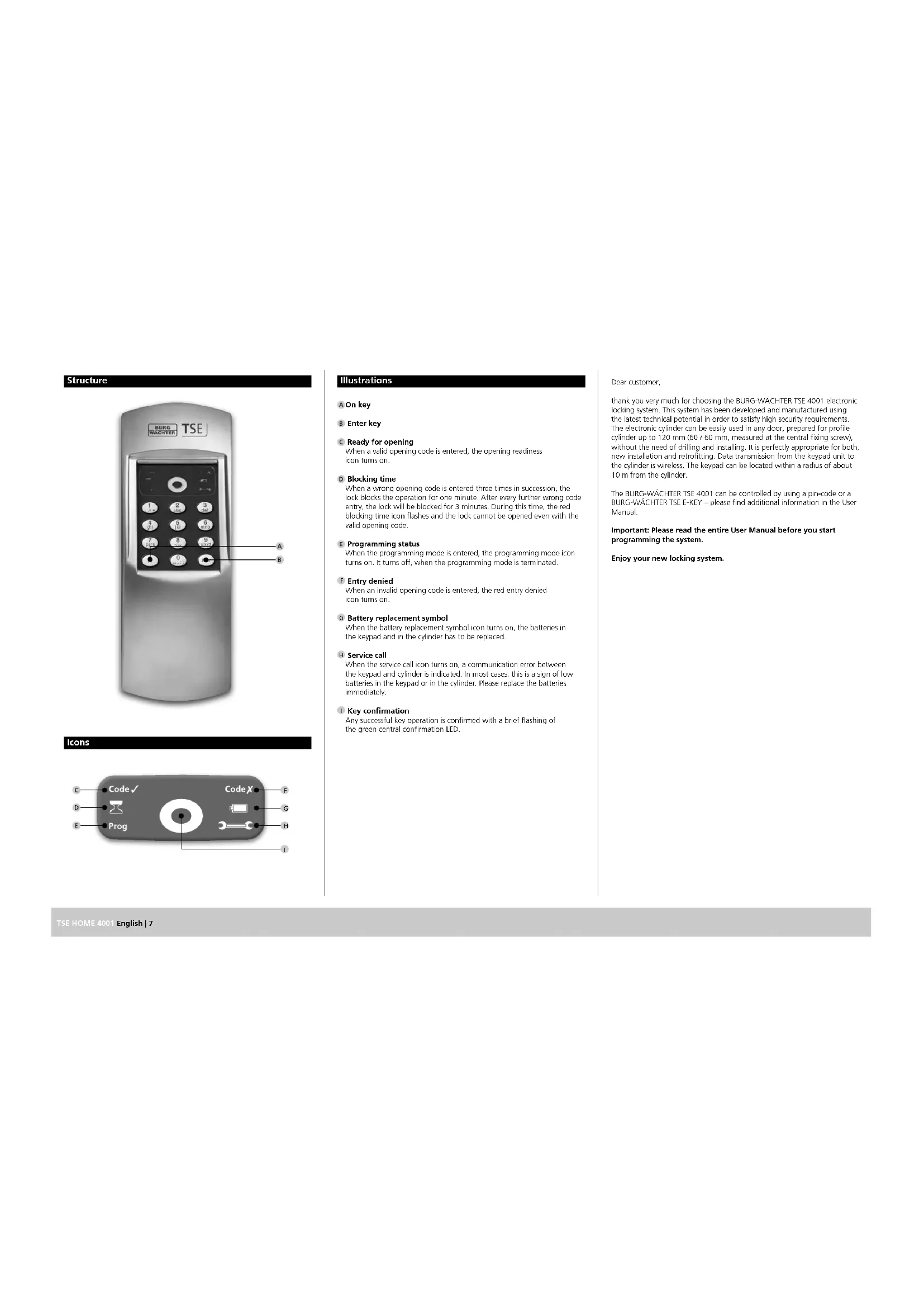
Mechanical assembly diagram showing a cylindrical component with internal shafts and mounting flanges (no text or labels)text_image
Code √ Prog Code X F G H IIllustrations
A On key
B Enter key
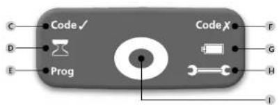
C Ready for opening
When a valid opening code is entered, the opening readiness icon turns on.
D Blocking time
When a wrong opening code is entered three times in succession, the lock blocks the operation for one minute. After every further wrong code entry, the lock will be blocked for 3 minutes. During this time, the red blocking time icon flashes and the lock cannot be opened oven with the valid opening code.
E Programming status
When the programming mode is entered, the programming mode icon turns on. It turns off, when the programming mode is terminated.
F Entry denied
When an invalid opening code is entered, the red entry denied icon turns on.
G Battery replacement symbol
When the battery replacement symbol icon turns on, the batteries in the keypad and in the cylinder has to be replaced.
H Service call
When the service call icon turns on, a communication error between the keypad and cylinder is indicated. In most cases, this is a sign of low batteries in the keypad or in the cylinder. Please replace the batteries immediately.
1 Key confirmation
Any successful key operation is confirmed with a brief flashing of the green central confirmation LED.
Dear customer,
thank you very much for choosing the BURG-WACHTER TSE 4001 electronic locking system. This system has been developed and manufactured using the latest technical potential in order to satisfy high security requirements. The electronic cylinder can be easily used in any door, prepared for profile cylinder up to 120 mm (60 / 60 mm, measured at the central fixing screw), without the need of drilling and installing. It is perfectly appropriate for both, new installation and retrofitting. Data transmission from the keypad unit to the cylinder is wireless. The keypad can be located within a radius of about 10 m from the cylinder.
The BURG-WÄCHTER TSE 4001 can be controlled by using a pin-code or a BURG-WÄCHTER TSE E-KEY – please find additional information in the User Manual.
Important: Please read the entire User Manual before you start programming the system.
Enjoy your new locking system.
TSE 4001 PINCODE
The electronic cylinder operates using a 6-digit pincode. In option to that, you can also use the TSE 5103 E-KEY.
Electronic cylinder TSE 4001
The TSE 4001 electronic cylinder includes
the following standard functions:
- Number of pincodes: 1
Number of E-KEYs: 5
Optional locking media
TSE 5103 E-KEY remote key
Administrator code
Factory setting: 123456 (you absolutely need to change this)
In the following description, the administrator code is referred to as "pincode".
Technical data
| Blocking times After | 3 x wrong pincode entry1 minute, then 3 minutes each time |
| Power supply for keypad | 2 x MIGNON LR6 AA ALKALINE |
| Power supply for cylinder | 2 x MICRO LR03 AAA ALKALINE |
| Permissible ambient conditions* | -15°C/+50°C/up to 95% relative air humidity (noncondensing) |
1. Commissioning
When the TSE 4001 pincode is first put into operation, it is necessary to perform a certain procedure, as the system is delivered from the factory in a special power saving mode.
- Press "On", the green "ready for opening"-icon flashes briefly
- Press "Enter" for approx. 5 seconds until the blocking time icon starts
flashing, while the green "ready for opening"-icon is on permanently - The blocking time icon turns off after approx. 20 seconds. Now enter the factory-set pincode (1-2-3-4-5-6).
When the procedure has been successfully finished, the "ready for
opening"-icon turns on, while in case of an incorrect procedure.
the "entry denied" icon flashes. In case, please repeat the procedure.
Menu functions
Besides numbers, the keypad also includes letters. In order to program individual functions, number or letter combinations must be typed. The initial letters of a program function create a code combination, intended for easy memorizing. Each submenu explicitly includes this.
1 Starting the programming mode to change the lock settings
- Press "On", then type in 76, press "Enter"
Enter the 6-digit pincode
- The green key confirmation LED flashes briefly and the program mode icon turns on.
The code combination "76" stands for "PM" - Programming Mode.
2 Changing the opening code (factory setting 1 2 3 4 5 6)
- Press "On", then type in 76, press "Enter
- Enter the current 6-digit pincode
- The green key confirmation LED flashes briefly and the program mode icon turns on.
- Type in your new 6-digit pincode and press "Enter"
- Repeat your new 6-digit pincode and press "Enter" briefly. If the green "ready for opening"-icon turns on, the code change was successful. In case the red "entry denied"-icon turns on, the code entry was wrong and the former settings persist.
3 Unblocking the lock
- Press the "On" key
- Type the 6-digit user code, then press the "Enter" key
- The green "ready for opening" icon goes on
- The lock can be opened by turning the door knob
4 Recording or overwriting an E-KEY in one
of the memory positions 1 to 5
- Press "On" then type in 76 press "Enter"
Enter the current 5-digit pincede
- The green key confirmation LED flashes briefly and the program mode icon turns on.
- Set the E-KEY into the programming mode hold the button on the E-KEY
until the green LED on the E-KEY flashes three times in succession)
- Type in 32X (X indicates the F-KEY position on the memory cell, numbers 1 to 5 are allowed), then press "Enter".
- You need to leave the programming code to activate the permission to access. Therefore press the button „On“ twice and enter the opening code via the keypad once.
As long as the programming mode is active, the icon „Prog“ is lit, other E-KEYS can be programmed without re-entering the code.
The combination "32" stands for "AE" - add E-KEY. When the action has been performed successfully, the green "ready for opening" LED turns on, while in case of rejection, the red "entry denied" one turns on.
You can note the names of the E-KEY users and the corresponding position numbers on page 16 of this User and Assembly Manual.
5 Deleting an E-KEY in one of the user positions 1 to 5
- Press "On", then type in 76, press "Enter"
- Enter the current 6-digit pincode
- The green key confirmation LED flashes briefly and the program mode icon turns on.
- Type 35X (X indicates the position of the E-Key, numbers 1 to 5 are allowed), then press the "Enter" key.
The code combination "35" stands for "RE" - remove E-KEY. When the action has been carried out successfully, the green "ready for opening" LED turns on, while in case of rejection the red "entry denied" one turns on.
6 Synchronising the E-KEY
- In this menu, the radio channel of the E-KEY can be synchronised to the channel of the keypad. This is necessary when the radio channel of the cylinder is modified, although E-KEYs with the old channel setup are still in use. - Set the E-KEY into the programming mode (hold the button on the E-KEY until the green LED on the E-KEY flashes three times in succession) - Type in "3/7", then press "Enter"
The combination "37" stands for "ES" – E-KEY sync. When the action has been carried out successfully, the green „ready for opening" LED turns on, while in case of rejection, the red „entry denied" one turns on.
7 Resetting the radio channel
- The radio channel can be reset here (12 channels to select from, factory setting: channel 1). This may be required when the radio channel is already used by another application, e.g. WLAN, which can possibly lead to interference. In such case, please select another channel with a spacing of at least 3 radio channels.
- Press "On", then type in 76, press "Enter"
- Enter the current 6-digit pincode
- The green key confirmation LED flashes briefly and the program mode icon turns on.
- Type 38X (X indicates the radio channel, numbers 1 to 12, also 01 etc., are allowed), then press the "Enter" key.
The combination "38" stands for "RC" - RF channel). When the action has been performed successfully, the green "ready for opening" LED goes on, while the red "entry denied" one goes on in case of error.
8 Registering the keypad
- Press "On", type in "82", then press "Enter".
- Type in the valid pincode
Attention: When registering a new cylinder, the factory code (123456) has to be entered.
When the action has been executed successfully, the green
„ready for opening" LED turns on, while in case of rejection,
the red "entry denied" one turns on.
In case a wrong key has been entered by mistake, the "On" key can generally be used to return to the initial lock setting. You can then restart the locking operation from the beginning.
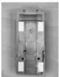
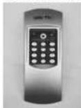
Keypad installation
1 Choose a place for fixing the keypad. Place the keypad within a maximum distance of approx. 10 m from the lock and carry out an opening test by entering the pincode. After a successful test, the keypad can be fixed using either the screws (3.9 x 22 and / or 3.9 x 12) or the attached adhesive pad. When using the screws, please remove the batteries before installation. Please install the keypad at a place, where it is protected against weather influences!
2 If required, replace the batteries and engage the housing cover onto the device box.
3 Carry out a function test of the unit while the door is open. In order to do so, enter the valid pincode several times.
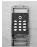
Keypad battery replacement
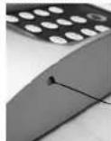
1 Remove the cover by pressing its detent notches on both sides with a pointed tool towards inside and pulling it up.
2 Insert the batteries into the keypad. Please check the correct polarity of the cells.
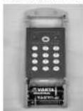
3 Place the cover on the keypad.
When inserting the new batteries, please check the correct polarity, which is indicated in the battery compartment of the keypad.
Installation instructions for TSE cylinder
The installation of the TSE cylinder is described below.
Please read this Manual carefully before the assembly and then store it at a safe place.
The cylinder is provided with a special detent system, offering you a possibility of using the cylinder for doors up to a thickness of 120 mm (60 / 60 mm, measured at the central fixing screws). No prior adjustment is necessary.
Attention:
Attention should be paid to prevent the door knob from being bumped, as the knob might be damaged.
The lock should not be greased or oiled.
The fixing of the knobs is provided with one incorporated hex screw in each knob.
Attention:
Never pull the outer knob completely from the shaft, as this will damage the electronics! The hex screw that fixes the knob onto the shaft must be loosened only slightly and it must always remain in the plastic knob, providing protection against pulling out the knob!
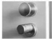
Outer side Inner side
Outer knob Inner knob
text_image
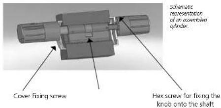
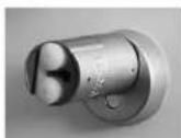
Schematic representation of an assembled gylinder. Cover Fixing screw Hex screw for fixing the knob onto the shaftRemark
The basic size of the cylinder is 30 mm for each side. When delivered, the cylinder is completely pushed together (smallest possible cylinder length). Before you embed the cylinder into the door, you need to adjust the exterior knob to door thickness.
To install the cylinder, proceed as follows:
1 Take a rough measurement of the door thickness (incl. fittings)
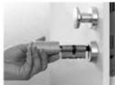
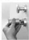
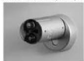
2 Pull the inner knob away from the shaft, move the outer knob over the detent system (spacing 2.85 mm) to the required dimension.

Schematic representation of adjustment of the outer knob
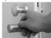
3 the TSE cylinder outside in through the mortise lock into the door and then tighten the fixing screw.
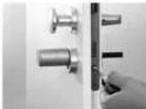
4 Shift the outer knob along the shaft until the required dimension is attained. Please make sure that the distance between the rotary knob and the door mounting is at least 1 mm. Then fix the knob using the hex key.
5 Shift the interior knob into the required position on the shaft and fix it with a distance of at least 1 mm from the strike plate by using the hex bolt.
Make sure that the interior knob is shifted on the shaft in a way that the fixing screw (inside the knob) faces the shaft with the little holes at the side.
6 The function test must be made while the door is open.
Replacing the knob batteries (exterior)
Attention: When replacing the batteries, make sure that no precipitations or humidity penetrate the batteries, as no water can escape when the compartment has been closed.
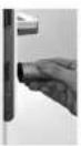
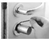
1 Loosen the hex screw on the cover and remove it. The fixing screw may be loosened only so far that the cover can be opened. It must never be unscrewed from the cover.
2 Pull the silicone cover out and replace the batteries. Check the correct polarity of the cells.
3 Place the silicone cover on the batteries, close the cover and tighten the fixing screw.
Disposal
Dear customer,
Please help us avoid unnecessary waste.
Should you intend to dispose of this device at any time, please remember that many components of this device contain valuable materials, which can be recycled.
Please be aware that electrical and electronic equipment and batonics shall not be disposed of as household waste, but rather collected separately. Please obtain information on the collecting points for electrical waste from the responsible authority of you municipality.


BURG-WÄCHTER KG hereby declares that this device complies with Directive 2014/53/EU, (RED) 2014/30/EU, (EMC), 2011/65/EU (RoHS).
The full text of the EU Declaration of Conformity can be found on www.burg.biz.
Structure
text_image
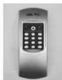
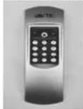
BURG WACHTER TSE 1 2 3 4 5 6 7 8 9 0 A BIcons
text_image
Code ✓ Prog Code X F G H IFigure
A Touche On
B Touche Enter
C Droit d'ouverture