ProfiScale MULTI PS 7455 - Measuring equipment Burg Wächter - Free user manual and instructions
Find the device manual for free ProfiScale MULTI PS 7455 Burg Wächter in PDF.
User questions about ProfiScale MULTI PS 7455 Burg Wächter
0 question about this device. Answer the ones you know or ask your own.
Ask a new question about this device
Download the instructions for your Measuring equipment in PDF format for free! Find your manual ProfiScale MULTI PS 7455 - Burg Wächter and take your electronic device back in hand. On this page are published all the documents necessary for the use of your device. ProfiScale MULTI PS 7455 by Burg Wächter.
USER MANUAL ProfiScale MULTI PS 7455 Burg Wächter
natural_image
Black-and-white photo of a mechanical device with a digital multimeter and foot, no visible text or symbolsBAJNA MULI 742957 (cm ^3 TACIB

200 mV
600 V

200μA
10A


Bedienungsanleitung

Operating instructions

Mode d'emploi

Gebruiksaanwijzing
www.burg.bizwww.burg.biz
Language
de Deutsch 4
en English 21
fr Français 38
nl. Nederlands 55
it Download: www.burg.biz/download
es Descarga: www.burg.biz/download
pt Download: www.burg.biz/download
50 Download: www.burg.biz/download
no Download: www.burg.biz/download
dk Download: www.burg.biz/download
natural_image
Close-up of a hand using a digital multimeter to test a small electronic component (no visible text or symbols)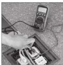
natural_image
Hand using a multimeter to test electrical components on a circuit board (no visible text or symbols)
text_image
0.0 MSR238C DIGITAL MULTIMETER SING HUBI TAN HCB TEMP +1.5V RUNG SELECTED COM +100%+100% +100%+100% any 10 sec.
natural_image
Digital multimeter with analog dial and control buttons (no visible text or labels)Einführung
natural_image
Symbol of a trash bin with crossed lines indicating no waste or discharge (no text or labels)Congratulations on the purchase of this BURG-WÄCHTER quality product! With the ProfiScale Multimeter PS 7455, you can perform measurements of voltage, electric current, resistance, temperature, diodes as well as continuity and battery checks. Easily and reliably measure all electric devices in the house – even sensitive electronic devices such as computers and television sets. With the help of the digital display, you can immediately read out the measurement results. A practical holder reassures an even more convenient reading of the display.
Safety instructions
Personal injuries can occur if following instructions are not being considered!
To ensure a safe working, please read the complete operating manual carefully before commissioning this device and store it away safely.
This digital meter PS 7455 has been conceptualised according to IEC-61010 1for electronical meters and belong to overvoltage category CAT III 600 V and to the insulation class II.
With appropriate handling and care, this digital meter will serve you well and satisfactorily for many years.
To assure a safe operation and to achieve the full range of functionality of the meter, please follow the instructions carefully.
- During usage of this meter, the user needs to consider these safety rules:
- Protection against hazards of electrical current.
- Protection against a misuse of the device.
- Please check the meter for damages before commissioning and only use the device if no damages are recorded.
- The measurement lines need to be in an immaculate condition.
Make sure that the insulation of the lines are not damaged and / or the conductors of the meter are not exposed. - Compliance with safety standards can be guaranteed only when using the included measurement lines.
- Before using, select the appropriate input jack, function and the measuring range.
- Always attach the black measurement line first, afterwards the red one. For removing, do so conversely.
- Only use the device with the backside casing and only if the casing is properly secured.
- Before you turn the selector switch to choose another measuring range, remove the measurement lines from the about to be tested circuit.
- Never exceed the prescribed limits of the respective ranges.
Be especially careful when measuring near the limit range. - If the meter is connected with another circuit, do not touch any free connectors.
- Do not measure electric voltage if the voltage of the connections exceeds 600V.
- Always be careful with measurements with a voltage of over 60 V DC or 30 V AC rms. During the measuring, hold your fingers behind the boundaries of the measurement lines.
- Never connect the measuring lines to a circuit if the selector switch is positioned on one of the following measuring ranges: Current measurement, electrical resistance measurement, temperature measurement and diode test or continuity check mode.
-
Never conduct resistance measurements, temperature measurements, diode tests and continuity checks on energised circuits.
-
Make sure that before measuring of diodes, electrical resistances or before continuity checks the about to be measured object is volt-free and all capacitors are fully discharged.
- Check the function of the meter with measuring a known circuit first. If you detect a deviation, do not use the meter any longer.
- If you detect any errors or anomalies, the device cannot be used anymore and needs to be professionally checked.
- Never try to fix the meter yourself.
- Do not dismount the device in order to avoid functional errors.
- Only let the meter be repaired by qualified professionals and only with genuine parts to obtain the device's safety and warranty.
- Before you open the battery case cover or the casing of the meter, always remove all measurement lines from all tested circuits.
- If you see the battery symbol ☐ on the display, immediately change the battery to avoid flawed measuring results. An accuracy of the meter is not reliable in this state which could lead to an electric shock.
- Always turn OFF the meter when not in use.
- If the meter is not used for a longer period of time, the battery should be removed to prevent damages of the device.
- To prevent fire, only use fuses with respective voltage and loading capacity: FF 400 mA H 600 V or FF 10 A H 600 V.
- Keep the device away from children and unauthorised persons.
- Do not use any abrasive cleaners or solvents for cleaning your device. Use a wet cloth and only mild cleaners.
- Do not use the device in approximate range of flammable or explosive gases.
- Handle the device carefully and do not drop it.
- Do not store the device in direct sunlight, at high temperatures, high humidity or precipitation.
- Store the device dry and safe.
- Avoid contact with water and dust.
Structure
text_image
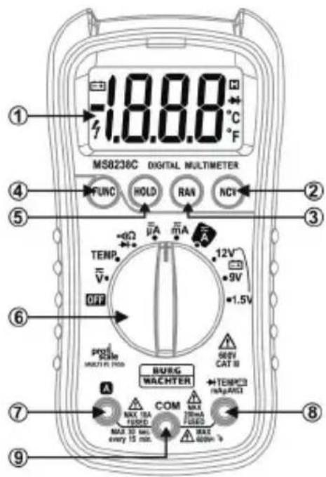
MS8238C DIGITAL MULTIMETER 1.8.8.0 °C F ① ② ③ ④ ⑤ ⑥ OFF TENP. V HOLD RAN NCI 12V 9V 1.5V PRO RATE MULTIPL FLOW BURG WACHTER MAX 10A FUSED MAX 30 sec. every 15 min. MAX 400mA MAX 10mA FUSED MAX 10mA COM MAX 10mA FUSED MAX 10mA COM MAX 10mA FUSED1 Display
2 NCV button
3 Range button RAN
4 Function button FUNC
5 Saving button HOLD
6 Selector switch
7 10 A input jack
8 Input jack (for all measurements, except for current measurement >200 mA)
9 Ground jack
Symbols
⚠️ Important safety information – Read the operating instructions
Attention, high safety risk
Double insulation (protection class II) CAT III overvoltage category III, contamination level 2 according to IEC61010-1
CE According to guidelines of the European Union
Earth lug Fuse
AC Alternating current/alternating voltage
DC Direct current/direct voltage
Diode
•)) Continuity buzzer
≈ AC or DC (alternating current or direct current)
v Volt
A Ampere
°C Celsius
°F Fahrenheit
DATA-H This indicates that the data of the display are being hold
AUTO Automatic measuring range

Battery change
Ω Electric resistance measurement
| Technical data | |
| Max. voltage between connections and earth | 600 V DC or AC rms |
| Fusing | μA / mA range: FF 400 mA H 600 V10 A range: FF 10 A H 600 V |
| Operating height | max. 2000 m (7000 ft.) |
| Display | 20 mm LCD |
| Max. display data | 1999 (3 1⁄2) |
| Polarity indicator | “-” shows negative polarity |
| Electrical overload limit | Display „OL" |
| Sampling time | Ca. 0.4 seconds |
| Device display | Display of functions and of electric capacity |
| Automatic shutdown | The device will turn off after 15 minutes when not in use |
| Power supply | 1x 9 V block battery |
| Measurement range selection | Automatic or manual |
| Operating temperature | 0 °C to 40 °C (32 °F to 104 °F) |
| Storage temperature | -10 °C to 60 °C (14 °F to 140 °F) |
| Relative humidity while operating | <80 % |
| Relative humidity while storage | <70 % |
| Accuracy | ±(% of display + number of decimal places); applies for temperatures from 18 °C to 28 °C with a relative humidity of < 80 %, for one year guaranteed |
| Measurement | 148 mm x 73,5 mm x 50 mm |
| Weight | Ca. 232 g |
Direct current voltage (DC)
Measurement range Resolution Accuracy
200mV 0.1 mV ± (0.5 % from rdg + 3 places)
2 V 0.001 V ± (0.5 % from rdg + 3 places)
20V 0.01 V± (0.5 % from rdg + 3 places)
200V 0.1 V ± (0.5 % from rdg + 3 places)
600V1V± (0.8 % from rdg + 3 places)
Input resistance: 10MΩ
Max. input voltage: 600 V DC
Overvoltage protection 600 V DC
Alternating voltage (AC)
Measurement range Resolution Accuracy
2 V 0.001 V ± (0.5 % from rdg + 5 places)
20V 0.01 V± (0.5 % from rdg + 5 places)
200V 0.1 V ± (0.5 % from rdg + 5 places)
600V1V± (1.0 % from rdg + 5 places)
Input resistance: 10MΩ
Max. input voltage: 600 V AC rms
Frequency range: 40 to 400 Hz
Responding qualities: average, calibrated in rms of the sine curve
Overvoltage protection: 600 V AC rms.
Direct current (DC)
| Measurement range Resolution Accuracy | ||
| 200μA | 0.1 μA | ± (0.8 % from rdg + 3 places) |
| 2000μA | 1 μA | ± (0.8% from rdg + 3 places) |
| 20 mA | 0.01 mA | ± (0.8 % from rdg + 3 places) |
| 200 mA | 0.1 mA | ± (0.8 % from rdg + 3 places) |
| 10 A | 10 mA | ± (1.0 % from rdg + 10 places) |
Max. input current: Input socket: 200 mA DC, 10 A socket: 10 A DC
Overvoltage protection: A, mA area: FF 400 mA H 600 V,
10 A area: FF 10 A H 600 V
If the measurement exceeds 2 A, do not measure continuously for more than 2 minutes. Wait 10 minutes until next measuring.
Alternating current
| Measurement range Resolution Accuracy | ||
| 200 μA | 0.1 μA | ± (1.0 % from rdg + 3 places) |
| 2000 μA | 1 μA | ± (1.0 % from rdg + 3 places) |
| 20 mA | 0.01 mA | ± (1.0 % from rdg + 3 places) |
| 200 mA | 0.1 mA | ± (1.2 % from rdg + 3 places) |
| 10 A | 10 mA | ± (1.5 % from rdg + 10 places) |
Max. input current: Input socket: 200mA AC rms, 10A socket: 10A AC rms
Frequency range: 40 to 400 Hz
Responding qualities: average, calibrated in rms of the sine curve
Overvoltage protection: A, mA area: FF 400 mA H 600 V,
10 A area: FF 10 A H 600 V
If the measurement exceeds 2 A, do not measure continuously for more than
2 minutes. Wait 10 minutes until next measuring.
Continuity check
Measurement range Function

The signal sounds when resistance is lower than 30
Open circuit voltage: ca. 0.5 V
Overvoltage protection: 600 V DC or AC rms
Resistance
Measurement range Resolution Accuracy
| 200Ω 0.1 Ω | ± (0.8 % from rdg + 4 places) |
| 2kΩ 0.001kΩ | ± (0.8 % from rdg + 4 places) |
| 20kΩ 0.01kΩ | ± (0.8 % from rdg + 4 places) |
| 200kΩ 0.1kΩ | ± (0.8 % from rdg + 4 places) |
| 2MΩ 0.001MΩ | ± (0.8 % from rdg + 4 places) |
| 20MΩ 0.01M | ± (1.0 % from rdg + 4 places) |
Overvoltage protection: 600 V DC or AC rms
Temperature
Measurement range Resolution Accuracy
| -20°C to 750°C | 1°C | ± (1% from rdg + 2 places) |
| -4°F to 1382°F | 1°F | ± (1% from rdg + 2 places) |
Overvoltage protection: 600 V DC or AC rms
Diode
Measurement range Resolution Accuracy
| 1,5V | 1 mV | The display shows the minimal forward bias of the diode. |
Overvoltage protection: 600 V DC or AC rms
Battery check
| Measurement range Resolution | Accuracy | |
| 1.5V | 0,001 V | ± (3.0% from rdg + 5 places) |
| 9V | 0,01 V | ± (0.8% from rdg + 7 places) |
| 12V | 0,01 V | ± (0.8% from rdg + 7 places) |
Overvoltage protection: 600 V DC or AC rms
Operating
General remarks on measuring
Choose a function according to the measured extent and turn the selector switch accordingly. If the voltage of the battery is lower than the normal operating voltage, this symbol appears. Change battery immediately.
The symbol ⚠ next to the input jack shows that the input voltage or input current should be lower than the maximum value listed on the meter – to protect the inner circuit. When connecting the measurement lines, please connect the earth lead (COM) first and only then the measurement lines. For loosening the measurement lines, remove the lines first and afterwards the earth lead (COM).
Automatic shutdown
After 14 minutes of disuse, the device announces the automatic shutdown with five short sounds. After another minute, the device shuts down automatically, signalised through a long signal at the end. After an automatic shutdown, to turn on the device again, you can turn the switch to any function. To deactivate the automatic shutdown, press "HOLD" button while you turn on the device.
Button functions
FUNC – function button for selecting measuring mode: When you are measuring current or voltage, you can switch with the “FUNC” button in between direct and alternating current measurement or direct and alternating voltage measurement. With temperature measurements, you can switch with the “FUNC” button between °C and °F. With the diodes and continuity checks, you can as well switch with “FUNC” between them.
HOLD – measurement storage: If you want to safe a measured value, please push the "HOLD" button. The symbol "DATA-H" appears on the display, the saved measured value is constantly displayed on the display. Pressing the button again, the measured value saving is being made void and the present value is being displayed.
RAN – range conversion: The automatic measuring range is being used with current-, voltage- and resistance measurements. Press the button “RAN” if a manual measuring range option is desired. Every actuating of the “RAN” button raises the measuring range. If the highest measuring range is reached, with pressing the button again, it starts with the lowest measuring range again. If you press the “RAN” button for more than 2 seconds, the automatic measuring range is being activated again.
NCV find contactless voltage source: Hold down the “NCV” button and move the Multimeter within the range of the about to be tested range. Very sensibly, the device indicates a possible voltage source with an acoustic signal and a flashing of the LED above the display. This function can be applied to every mode.
Measuring of direct current voltage
Attention! Input voltages over 600 V DC cannot be measured. Higher input voltages can lead to personal damages and / or to damages of the device. Be sure not to get an electric shock while measuring.
- Connect the black measurement line to the ground jack COM and the red measurement line to the input jack.
- Switch the selector switch to the voltage range. Determine the measuring range manually with the help of the RAN button or use the pre-set automatic measuring range option.
-
Connect the measurement lines for measuring voltage parallel to the voltage source.
-
The polarity of the red measurement line connection is displayed on the LC display.
- If a too low measuring range that is being exceeded during measuring is being selected, "OL" appears on the display. Then, please select a higher measuring range.
- With choosing a low measuring range and open measurement lines, "measured values" might be displayed through electric interfering fields. As soon as the measurement lines are being connected with the measured object, real measured values are being displayed.
Measuring of alternating voltage
Attention! Input voltages over 600 V AC rms cannot be measured. Higher measuring ranges can lead to personal damages and/or to damages of the device. Be sure not to receive an electric shock during high-voltage measurements.
- Connect the black measurement line to the ground jack COM and the red measurement line to the input jack.
- With the selecting switch, select the voltage range. Press the "FUNC" button to choose the alternating voltage measurement. Determine the measuring range manually with the help of the RAN button or use the pre-set automatic measuring range option.
- Connect the measurement lines for measuring voltage parallel to the voltage source.
- The measured values are being displayed on the LC display.
- If a too low measuring range that is being exceeded during measuring is being selected, "OL" appears on the display. Then, please select a higher measuring range.
- With choosing a low measuring range and open measurement lines, "measured values" might be displayed through electric interfering fields. As soon as the measurement lines are being connected with the measured object, real measured values are being displayed.
Measuring of direct current
Attention! Turn off the power of the about to be measured circuit before connecting the meter and make sure that all capacitors are fully discharged. Always check fuses prior to current measurements.
- For a max. current measuring of 200 mA, please connect the black measurement line to the ground jack COM and the red one to the input jack. For a max. measurement of 10 A, please remove the red measurement line and connect it to the 10 A jack.
- Turn the selector switch to the desired measuring range A, mA, or A. Determine the measuring range manually with the help of the RAN button or use the pre-set automatic measuring range option.
- Connect the measurement lines for measuring a current only in series with the current source, only then activate the circuit.
- The polarity of the red measurement line connection is displayed on the LCD display.
- If a too low measuring range that is being exceeded during measuring is being selected manually, "OL" appears on the display. Then, please select a higher measuring range.
- With the input jack of 200 mA, the max. input current should not exceed 200 mA as an overvoltage may damage the fuse. With a higher current, the input jack 10 A for max. 10 A input current needs to be used.
Measuring of alternating current
Attention! Turn off the power of the about to be measured circuit before connecting the meter and make sure that all capacitors are fully discharged. Always check fuses prior to current measurements.
- For a max. current measuring of 200 mA, please connect the black measurement line to the ground jack COM and the red one to the input jack. For a max. measurement of 10 A, please remove the red measurement line and connect it to the 10 A jack.
- Turn the selector switch to the desired measuring range A, mA, or A. Press "FUNC" to select alternating current measuring. Determine the measuring range manually with the help of the RAN button or use the pre-set automatic measuring range option.
-
Connect the measurement lines for measuring a current only in series with the current source, only then activate the circuit.
-
The measured values are displayed on the LCD display.
- If a too low measuring range that is being exceeded during measuring is being selected manually, "OL" appears on the display. Then, please select a higher measuring range.
- With the input jack of 200 mA, the max. input current should not exceed 200 mA as an overvoltage may damage the fuse. With a higher current, the input jack 10 A for max. 10 A input current needs to be used.
Measuring electrical resistance
Attention! Make sure when measuring internal resistance that the about to be measured object is volt-free and that all capacitors are fully discharged.
- Connect the black measurement line to the ground jack COM and the red line to the input jack.
- Turn the selector switch to the measuring range . Determine the measuring range manually with the help of the RAN button or use the pre-set automatic measuring range option.
- Connect the measurement lines for measuring the resistance parallel to the measured resistance.
- The measured values are displayed on the LCD display.
- With a disconnection of the measuring circuit, the symbol "OL" appears on the display. With this, the transgression of the measuring range value is being indicated.
Please note! During the measuring of a resistance, a slight deviating value to the data of the resistance can be displayed as the test current of the Multimeter runs parallel to the measured circuit. To increase the accuracy during measuring smaller resistances, connect both of the measurement lines short-time at first and note down the value. Afterwards, subtract the value from the value of the actual resistance measurement.
Measuring temperature
Attention! Do not connect the thermal element with voltage-carrying components to avoid an electric shock.
- Switch the selector switch to "TEMP".
- Press the "FUNC" button to select either °C or °F.
- The LCD display shows the current ambient temperature.
- For a temperature measurement, the included sensing element with a thermal element type "K" is to be used. Onto the plug of the thermal element, the positive and negative poles are marked. Connect the negative pole to the ground jack COM and the positive pole to the input jack, marked with TEMP. With the end of the temperature measuring sensor, touch the about to be measured object.
- The values are displayed on the LC display.
- To achieve a more accurate measured value, the meter and the temperature measuring sensor should be adjusted to the ambient temperature before measuring.
Diode check
Attention! Make sure that the about to be measured object is volt-free and that all capacitors are fully discharged.
- Connect the black measurement line to the ground jack COM and the red line to the input jack. (The polarity of the red measurement line is “+”).
- Select with the selector switch the function
- Press the "FUNC" button to change to diode check. The symbol appears on the display.
- For diode check, please connect the red measurement line with the anode (+) and the black line with the cathode (-) of the diode.
- The values are being displayed on the display.
- The meter shows a minimal forward bias of the diode.
- If the measurement connections are wrongly polarised, only "OL" appears on the display.
Continuity check
Attention! Make sure that during the continuity check, the about to be measured object is volt-free and hat all capacitors are fully discharged.
- Connect the black measurement line to the ground jack COM and the red line to the input jack.
- Switch the selector switch to the position •)))
- Press the button "FUNC" twice to select continuity check. The symbol appears on the display.
- During the continuity check, connect both of the measurement lines parallel to the object.
- If continuity exists (resistance is lower than 30 ), the built-in buzzer will sound.
- If the measurement lines are reversely polarised, only "OL" will appear on the display.
Battery check
Attention: Only connect the meter with batteries with max. 30 V DC or 60 V AC. A higher input voltage can be displayed but can lead to damages of the inner circuit.
- Connect the black measurement line to the ground jack COM and the red line to the input jack.
- Switch the selecting switch to the desired 1.5 V, 9 V or 12 V measuring range.
- During the battery check, connect the measuring lines parallel to the battery.
- Together with the values on the LC display, the state of charge is being displayed.
Replacing battery
Attention! Before opening the battery case cover of the meter, make sure that all measurement lines are removed and the device is turned off to prevent the hazard of an electric shock.
- If this symbol appears on the display, the battery should be changed immediately to prevent possible hazardous situations.
- Loosen the screw of the battery case cover on the back of the device and remove the case cover.
- Replace the empty battery with a 9 V block battery.
- Close the battery case with the cover again and screw it down.
Replacing fuses
Attention! Before opening the battery case cover of the meter, make sure that all measurement lines are removed and the device is turned off to prevent the hazard of an electric shock. Only use fuses with the required values: F1 FF 400 mA H 600 V, F2 FF 10 A H 600 V.
- Fuses only need to be replaced rarely. A blasting of a fuse is often a consequence to a faulty operation.
- Loosen the screw of the battery case cover and remove the battery.
- Remove the green rubber cover of the device. Loosen the four screws of the casing and remove it.
- Replace the blown fuse with a new fuse with the appropriate capacity.
- Close the casing again and screw it down. Place the device back in the green rubber cover again. Afterwards screw firm the battery case cover after placing the battery.
Replacing measurement lines
Attention! A warranty is only given when the included measurement lines are used according to the safety standards. If required, they are to be replaced with the help of the same model or with measurement lines of the same appropriate capacity.
- Required capacity of the measurement lines: 600 V 10 A.
- You have to remove the measurement lines if the insulation is damaged.
Cleaning instructions
For cleaning, neither alcohol-containing (spiritus, SIDOLIN ^® or cleaners alike) nor aggressive cleansers (acetone or likewise) must be used. Dusted or dirty surfaces can simply be cleaned with a wet cloth.
Dirt at the pins of the measurement lines can influence the measured values. For cleaning the measurement lines, the device needs to be turned off first and the measurement lines need to be removed. Remove dirt thoroughly. For cleaning of the pins, you can for example moisten a cloth with some lubricant (e.g. WD-40).
Warranty
To provide you with an impeccable and high-quality product and to optimally help you in case of service and repair, it is necessary to hand in defective devices at your retailer together with the original proof of purchase. For a return according to your cancellation right, all units of the device need to be undamaged. In a case of disregard, the warranty expires.
Disposal of the device
Dear customer,
Please help to reduce waste. If you consider to dispose of this device, please remember that many components are made of valuable materials that can be recycled.

natural_image
Symbol of a trash bin with crossed lines indicating no waste or restriction (no text or labels)We point to the fact that electronical and electronic devices, as well as batteries are not to be disposed via the household rubbish but need to be collected separately. Please inform yourself about collecting points for electric waste at your local competent authority.

For questions regarding the EG declaration of conformity, please contact info@burg.biz
Printing errors as well as technical alterations reserved.
Introduction
DC Courant continu/tension continue
Diode
Tension continue (CD)
natural_image
Simple line drawing of a trash bin with crossed lines indicating no waste or discharge (no text or symbols)Overspanningsbeveiliging: 600 V DC of AC rms
Weerstand
Overspanningsbeveiliging: 600 V DC of AC rms
Temperatuur
Overspanningsbeveiliging: 600 V DC of AC rms
Diode
Overspanningsbeveiliging: 600 V DC of AC rms
Batterijtest
Overspanningsbeveiliging: 600 V DC of AC rms