Tidal II AK7448AS - Basket Zephyr - Free user manual and instructions
Find the device manual for free Tidal II AK7448AS Zephyr in PDF.

User questions about Tidal II AK7448AS Zephyr
0 question about this device. Answer the ones you know or ask your own.
Ask a new question about this device
Download the instructions for your Basket in PDF format for free! Find your manual Tidal II AK7448AS - Zephyr and take your electronic device back in hand. On this page are published all the documents necessary for the use of your device. Tidal II AK7448AS by Zephyr.
USER MANUAL Tidal II AK7448AS Zephyr
EN Use, Care, and Installation Guide
natural_image
Isometric line drawing of a technical enclosure or cabinet with a circular component mounted on top (no text or symbols)
Zephyr Connect
ACT ^TM
Airflow Control Technology

Page Safety Information 4-6
Types of Safety Warnings 4
General Safety 4-5
Operation 6
Electrical Requirements 6
Federal Communication Commission Interface Statement ...... 6
List of Materials 7
Installation Instructions 8-20
Ducting Calculation Sheet 8
Mounting Height, Clearance, & Ducting 9-10
Ducting Options ....11
Hood Specifications ....12
Electrical Supply 13
Cable Lock 13
Horizontal Ducting Conversion 14-16
PBD-1300B Dual Blower Installation 17-19
Mounting the Hood 20
Features & Controls 21-27
Proximity Controls 21-23
Zephyr Connect 24-25
Optional RF Remote Control 26-27
Maintenance 28-30
Hood & Filter Cleaning 28-29
LumiLight LED 30
ACT™ Conversion 31-33
Airflow Control Technology (ACT™) 31
Enabling ACT™ 32-33
Wiring Diagram 34-35
Troubleshooting.... 36-38
List of Parts & Accessories ....39
Notes....40
Limited Warranty 41
Product Registration 42
READ AND SAVE THESE INSTRUCTIONS
Your safety and the safety of others are very important.
We have provided many important safety messages in this manual for your appliance. Always read and obey all safety messages.

This is the Safety Alert Symbol. This symbol alerts you to potential hazards that can cause severe bodily injury or death. All safety messages will follow the Safety Alert Symbol and either the words "DANGER" "WARNING" or "CAUTION"

DANGER

Danger means that failure to heed this safety statement may result in severe injury or death.

WARNING

Warning means that failure to heed this safety statement may result in extensive product damage, serious personal injury, or death.

CAUTION

Caution means that failure to heed this safety statement may result in minor or moderate personal injury, property or equipment damage.
General Safety

WARNING

To reduce the risk of fire or electric shock, do not use this fan with any solid-state control device.

WARNING

WARNING - TO REDUCE THE RISK OF FIRE, ELECTRIC SHOCK, OR INJURY TO PERSONS, OBSERVE THE FOLLOWING:
a) Use this unit only in the manner intended by the manufacturer. If you have questions, contact the manufacturer.
b) Before servicing or cleaning unit, switch power off at service panel and lock the service disconnecting means to prevent power from being switched on accidentally. When the service disconnecting means cannot be locked, securely fasten a prominent warning device, such as a tag, to the service panel.

CAUTION

For General Ventilating Use Only. Do Not Use To Exhaust Hazardous Or Explosive Materials And Vapors. Take care when using cleaning agents or detergents. Suitable for use in household cooking area.

WARNING

WARNING - TO REDUCE THE RISK OF A RANGE TOP GREASE FIRE:
a) Never leave surface units unattended at high settings. Boilovers cause smoking and greasy spillovers that may ignite. Heat oils slowly on low or medium settings.
b) Always turn hood ON when cooking at high heat or when flambeing food. (i.e. Crepes Suzette, Cherries Jubilee, Peppercorn Beef Flambe').
c) Clean ventilating fans frequently. Grease should not be allowed to accumulate on fan or filter.
d) Use proper pan size. Always use cookware appropriate for the size of the surface element.
READ AND SAVE THESE INSTRUCTIONS

WARNING

WARNING - TO REDUCE THE RISK OF INJURY TO PERSONS IN THE EVENT OF A RANGE TOP GREASE FIRE, OBSERVE THE FOLLOWING ^a :
a) SMOTHER FLAMES with a close-fitting lid, cookie sheet, or metal tray, then turn off the burner. BE CAREFUL TO PREVENT BURNS. If the flames do not go out immediately, EVACUATE AND CALL THE FIRE DEPARTMENT.
b) NEVER PICK UP A FLAMING PAN – You may be burned.
c) DO NOT USE WATER, including wet dishcloths or towels – a violent steam explosion will result.
d) Use an extinguisher ONLY if:
1) You know you have a Class ABC extinguisher, and you already know how to operate it.
2) The fire is small and contained in the area where it started.
3) The fire department is being called.
4) You can fight the fire with your back to an exit
°Based on "Kitchen Firesafety Tips" published by NFPA.

WARNING

WARNING
TO REDUCE THE RISK OF FIRE, USE ONLY METAL DUCTWORK.

CAUTION

To reduce risk of fire and to properly exhaust air outside, do not vent exhaust air into spaces within walls, ceilings, attics, crawl spaces, or garages.

WARNING

WARNING - TO REDUCE THE RISK OF FIRE, ELECTRIC SHOCK, OR INJURY TO PERSONS, OBSERVE THE FOLLOWING:
a) Installation work and electrical wiring must be done by qualified person(s) in accordance with all applicable codes and standards, including fire-rated construction.
b) Sufficient air is needed for proper combustion and exhausting of gases through the flue (chimney) of fuel burning equipment to prevent back drafting. Follow the heating equipment manufacturer's guideline and safety standards such as those published by the National Fire Protection Association (NFPA), and the American Society for Heating, Refrigeration and Air Conditioning Engineers (ASHRAE), and the local code authorities.
c) When cutting or drilling into wall or ceiling, do not damage electrical wiring and other hidden utilities.
d) Ducted fans must always be vented to the outdoors.
e) If this unit is to be installed over a tub or shower, it must be marked as appropriate for the application and be connected to a GFCI (Ground Fault Circuit Interrupter) - protected branch circuit.

WARNING

Prop. 65 Warning for California Residents: This product may contain chemicals known to the State of California to cause cancer, birth defects, or other reproductive harm.
READ AND SAVE THESE INSTRUCTIONS
Operation
▶ Always leave safety grilles and filters in place. Without these components, operating blowers could catch onto hair, fingers and loose clothing.
The manufacturer declines all responsibility in the event of failure to observe the instructions given here for installation, maintenance and suitable use of the product. The manufacturer further declines all responsibility for injury due to negligence and the warranty of the unit automatically expires due to improper maintenance.
NOTE: Please check www.zephyronline.com for revisions before doing any custom work.
Electrical Requirements
Important:
▶ Observe all governing codes and ordinances.
It is the customer's responsibility to be aware of these below:
▶ To contact a qualified electrical installer.
To assure that the electrical installation is adequate and in conformance with National Electrical Code, ANSI/NFPA 70 latest edition* or CSA standards C22.1-94, Canadian Electrical Code, Part 1 and C22.2 No.0-M91 - latest edition** and all local codes and ordinances.
If codes permit and a separate ground wire is used, it is recommended that a qualified electrician determine that the ground path is adequate.
▶ Do not ground to a gas pipe.
▶ Check with a qualified electrician if you are not sure the range hood is properly grounded.
▶ Do not have a fuse in the neutral or ground circuit.
This appliance requires a 120V 60Hz electrical supply and connected to an individual properly grounded branch circuit protected by a 15 or 20 ampere circuit breaker or time delay fuse. Wiring must be 2 wire with ground. Please also refer to Electrical Diagram on product.
▶ A cable locking connector (not supplied) might also be required by local codes. Check with local requirements, purchase and install appropriate connector if necessary.
* National Fire Protection Association Batterymarch Park, Quincy, Massachusetts 02269
** CSA International 8501 East Pleasant Valley Road, Cleveland, Ohio 44131-5575
Federal Communication Commission Interface Statement
This equipment has been tested and found to comply with the limits for a Class B digital device, pursuant to Part 15 of the FCC Rules. These limits are designed to provide reasonable protection against harmful interference in a residential installation.
This equipment generates, uses and can radiate radio frequency energy and, if not installed and used in accordance with the instructions, may cause harmful interference to radio communications. However, there is no guarantee that interference will not occur in a particular installation. If this equipment does cause harmful interference to radio or television reception, which can be determined by turning the equipment off and on, the user is encouraged to try to correct the interference by one of the following measures:
▶ Reorient or relocate the receiving antenna.
▶ Increase the separation between the equipment and receiver.
Connect the equipment into an outlet on a circuit different from that to which the receiver is connected.
Consult the dealer or an experienced radio/TV technician for help.
Parts Supplied
| Quantity Part | |
| 1 | H |
| 2 Pro baffle filters (AK7400AS, AK7436AS) | |
| 3 Pro baffle filters (AK7448AS) | |
| 2 LumiLight LED, 6W (pre-installed) (AK7400AS, AK7436AS) | |
| 4 LumiLight LED, 6W (pre-installed) (AK7448AS) | |
| 1 8" round backdraft damper (pre-installed) | |
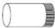
| 1 3-1/4" x 10" rectangular collar with damper | |
| 1 Single blower motor (pre-installed) | |
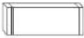
| 1 Top cover plate (for horizontal ducting) | |
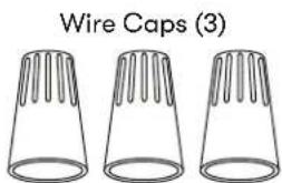
| 1 Hardware package | |
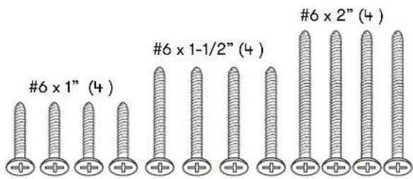
text_image
#6 x 1" (4) #6 x 1-1/2" (4) #6 x 2" (4)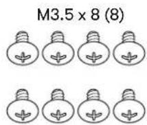
text_image
Wire Caps (3)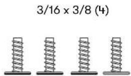
text_image
3/16 × 3/8 (4)Parts Not Supplied
| Ducting, conduit and all installation tools |
| Cable locking connector (if required by local codes) |
| Duct cover extension kit |
| Recirculating kit |
| RF remote control |
| Dual blower motor |
| Wood board to hang hood (WxDxH) |
AK7400AS: 27" × 1/2" × 4"
AK7436AS: 33" × 1/2" × 4"
AK7448AS : 45" x 1/2" x 4"
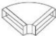
Ducting Calculation Sheet
| Duct pieces | Equivalent number length x used = | Total | |
 | 3-1/4"x 10" Rect., straight | 1 Ft. x( ) = | Ft. |
 | 6",7",8",10" Round, straight | 1 Ft. x( ) = | Ft. |
 | 3-1/4"x 10" Rect.90° elbow | 15 Ft. x( ) = | Ft. |
 | 3-1/4"x 10" Rect.45° elbow | 9 Ft. x( ) = | Ft. |
 | 3-1/4"x 10" Rect.90° flat elbow | 24 Ft. x( ) = | Ft. |
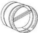
 | 7" to 6" or 8" to 7" Round tapered reducer | 25 Ft. x( ) = | Ft. |
 | 6",7",8" Round in-line damper | 15 Ft. x( ) = | Ft. |
 | 6",7",8",10" Round, 90° elbow | 15 Ft. x( ) = | Ft. |
 | 6",7",8",10" Round, 45° elbow | 9 Ft. x( ) = | Ft. |
| Subtotal column 1 = | Ft. | ||
Maximum Duct Length: For satisfactory air movement, the total duct length should not exceed 150 equivalent feet.
| Duct pieces | Equivalent number length x used = | Total | |
 | 3-1/4"x 10"Rect. to6" round transition | 5 Ft. x( ) = | Ft. |
 | 3-1/4"x 10"Rect. to6" round transition90° elbow | 20 Ft. x( ) = | Ft. |
 | 6" round to3-1/4"x 10"rect.transition | 1 Ft. x( ) = | Ft. |
 | 6" round to3-1/4"x 10"rect.transition90° elbow | 16 Ft. x( ) = | Ft. |
 | 7" round to3 1/4" x 10"rect.transition | 8 Ft. x( ) = | Ft. |
 | 7" round to3-1/4" x 10"rect.transition90° elbow | 23 Ft. x( ) = | Ft. |
 | 3-1/4"x 10"Rect.wall capwith damper | 30 Ft. x( ) = | Ft. |
 | 6",7",8",10"Round, wallcap withdamper | 30 Ft. x( ) = | Ft. |
 | 6",7",8",10"Roundroof cap | 30 Ft. x( ) = | Ft. |
| Subtotal column 2 =Subtotal column 1 =Total ductwork = | Ft. | ||
| Ft. | |||
| Ft. | |||
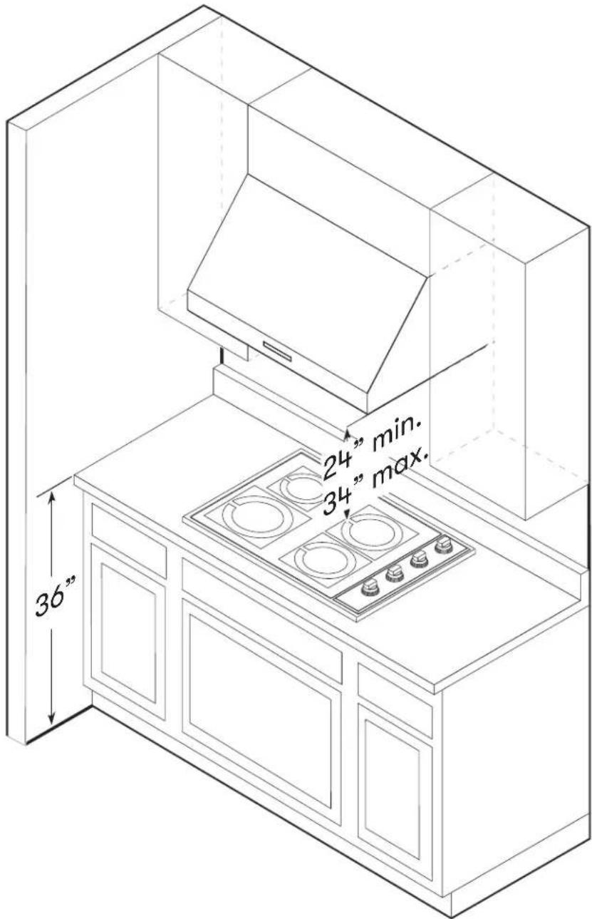
Mounting Height, Clearance, & Ducting
text_image
24" min. 34" max. 36"Mounting Height, Clearance, & Ducting
A minimum of 8" round duct or 3-1/4" x 10" rectangular duct is recommended to maintain maximum air flow efficiency for single blower and 10" round duct for dual internal blower for both vertical and horizontal ducting.
Always use rigid type metal ducts only. Flexible ducts could restrict air flow by up to 50%.
Also use the ducting calculation sheet (on page 11) to compute total available duct run when using elbows, transitions and caps.
ALWAYS, when possible, reduce the number or transitions and turns. If long duct run is required, increase duct size from 8" to 10".
If turns or transitions are required; install as far away from hood duct output and as far apart, between the two as possible.
Minimum mount height between range top to hood bottom should be no less than 24".
Maximum mount height should be no higher than 34".
It is important to install the hood at the proper mounting height. Hoods mounted too low could result in heat damage and fire hazard; while hoods mounted too high will be hard to reach and will lose its performance and efficiency.
If available, also refer range manufacturer's height clearance requirements and recommended hood mounting height above range. Always check your local codes for any differences.
Duct cover extension kit available for ceiling heights up to 12 feet. Turn to the list of parts and accessories section for part number and ordering information.
For shipment and installation damages:
▶ Please fully inspect unit for damage before installation.
If the unit is damaged in shipment, return the unit to the store in which it was bought for repair or replacement.
If the unit is damaged by the customer, repair or replacement is the responsibility of the customer.
If the unit is damaged by the installer (if other than the customer), repair of replacement must be made by arrangement between customer and installer.
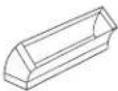
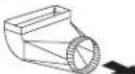
Ducting Options

WARNING

Fire Hazard: NEVER exhaust air or terminate ductwork into spaces between walls, crawl spaces, ceilings, attics, or garages. All exhaust must be ducted to the outside, unless using the recirculating option.
▶ Use single wall rigid metal ductwork only.
▶ Fasten all connections with sheet metal screws and tape all joints w/ certified Silver Tape or Duct Tape.
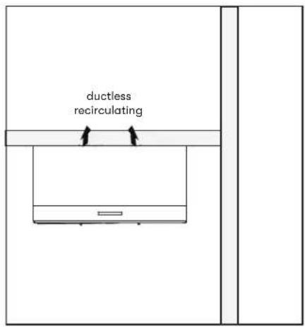
text_image
ductless recirculating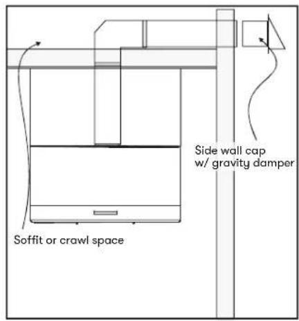
text_image
Side wall cap w/ gravity damper Soffit or crawl space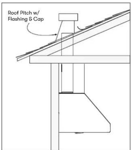
text_image
Roof Pitch w/ Flashing & Cap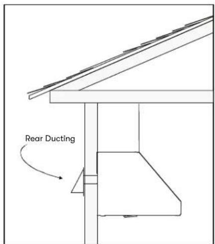
text_image
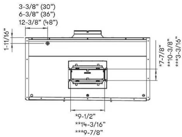
Rear DuctingHood Specifications
Top
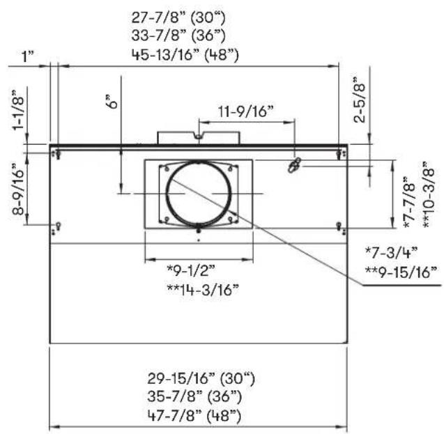
text_image
27-7/8" (30") 33-7/8" (36") 45-13/16" (48") 1" 6" 11-9/16" 2-5/8" 8-9/16" *7-7/8" **10-3/8" *9-1/2" **14-3/16" *7-3/4" **9-15/16" 29-15/16" (30") 35-7/8" (36") 47-7/8" (48")Side
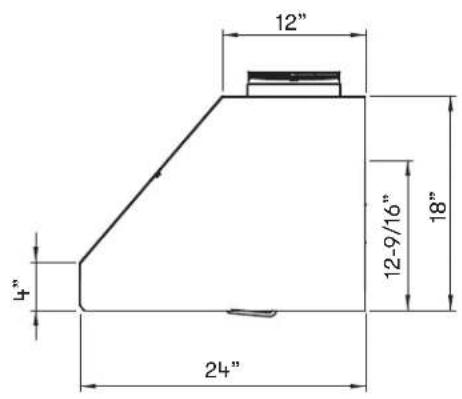
text_image
12" 4" 24" 12-9/16" 18"* 8" round ducting
** 10" round ducting
*** Rectangular ducting
Back
text_image
3-3/8" (30") 6-3/8" (36") 12-3/8" (48") 1-11/16" *7-7/8" **10-3/8" ***3-3/16" *9-1/2" **14-3/16" ***9-7/8"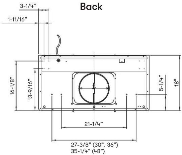
text_image
Back 3-1/4" 1-11/16" 16-1/8" 13-9/16" 5-1/4" 18" 21-1/4" 27-3/8" (30", 36") 35-1/4" (48")Electrical Supply

WARNING

Electrical wiring must be done by qualified person(s) in accordance with all applicable codes and standards. Turn off electrical power at service entrance before wiring.
For personal safety, remove house fuse or open circuit breaker before beginning installation. Do not use extension cord or adapter plug with this appliance.
Follow national electrical codes or prevailing local codes and ordinances.
This appliance requires a 120V 60Hz electrical supply, and connected to an individual, properly grounded branch circuit, protected by a 15 or 20 ampere circuit breaker or time delay fuse. Wiring must be 2 wire w/ ground. Please also refer to the Electrical Diagram labeled on product.
Cable Lock
A cable locking connector (not supplied) might be required by local codes. Check with local requirements and codes, purchase and install appropriate connector if necessary. (FIG. A)
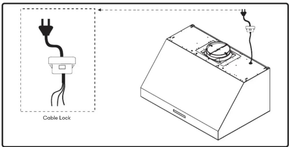
text_image
Cable LockFIG. A
Horizontal Ducting Conversion
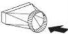
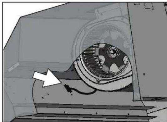
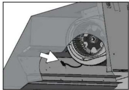
By default the Tidal II is pre-configured for 8" round vertical ducting. These steps are for 8" round and 3-1/4"x10" rectangular horizontal ducting. If you are continuing with vertical ducting, please skip these steps.
natural_image
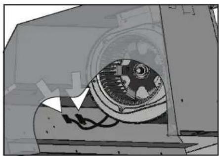
Illustration of a mechanical device inside a container with an arrow pointing to a component (no text or symbols visible)- Disconnect blower plug.
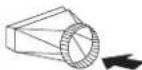
natural_image
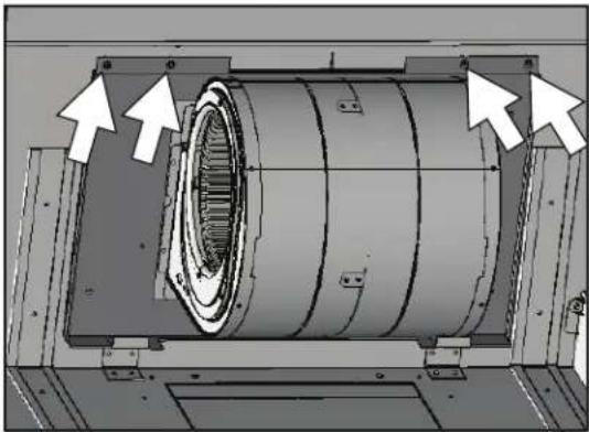
Technical diagram of a mechanical assembly with directional arrows indicating components (no text or symbols present)- Remove (4) screws from interior of hood body attaching single blower plate to top of hood body. Remove single blower and single blower plate.
text_image
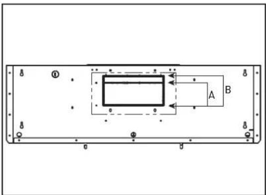
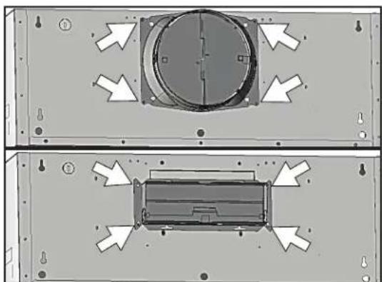
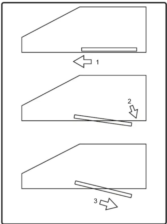
A B- Using a flat-head screwdriver, remove the smaller rectangular knock-out plate (A) for 3-1/4" x 10" rectangular ducting or the larger knock-out plate (B) for 8" round ducting located on the back of hood.
Horizontal Ducting Conversion
natural_image
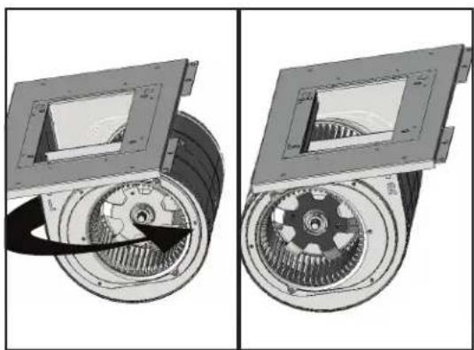
Mechanical assembly diagram showing two views of a gear assembly with no visible text or symbols- Remove (4) screws attaching blower to blower plate. Turn blower 180 degrees and reattach to blower plate.
natural_image
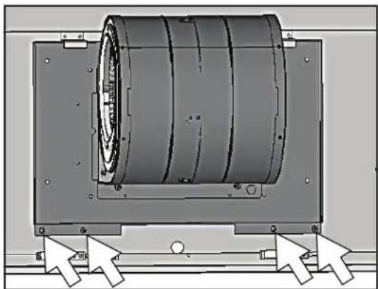
Mechanical assembly diagram showing a cylindrical component mounted on a frame with directional arrows indicating motion or force (no text or symbols present)- Position single blower with single blower plate as shown. Be sure to tuck back of single blower plate into tabs at back of hood. Secure single blower plate to back of hood using (4) screws removed from step 2.
natural_image
Technical diagram showing two views of a mechanical component with directional arrows indicating movement (no text or symbols present)- Attach 8" round duct collar or 3-1/4" x 10" rectangular duct collar to back of hood body using (4) M3.5 x 8 screws.
Horizontal Ducting Conversion
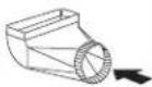
natural_image
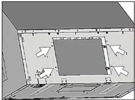
Diagram of a room interior with directional arrows indicating movement or flow (no text or symbols present)- From inside hood body, position top cover plate to top of hood body. From outside hood body, attach top cover plate to top of hood body using (4) 3/16 x 3/8 screws.
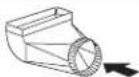
natural_image
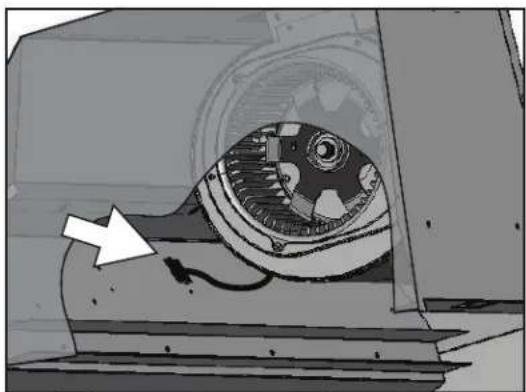
Illustration of a mechanical device inside a housing, showing internal components and a white arrow pointing to a component (no text or symbols present)- Connect blower plug.
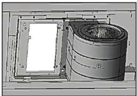
PBD-1300B Dual Blower Installation
This range hood is equipped standard with a single blower vertical duct option. To convert from single blower vertical ducting to dual blower vertical ducting please following the instructions below.
PBD-1300B dual blower kit is compatible with all Tidal II sizes.
natural_image
Diagram of a mechanical component with a rotating fan and directional arrow (no text or symbols)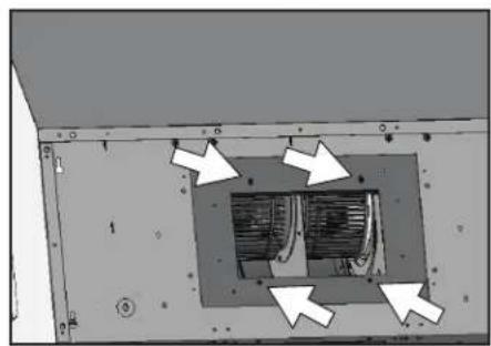
natural_image
Interior view of an industrial or mechanical component with a central chamber and directional arrows indicating flow or movement (no text or symbols present)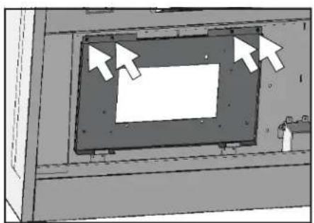
natural_image
Diagram of a mechanical component with arrows pointing to a rectangular frame (no text or symbols)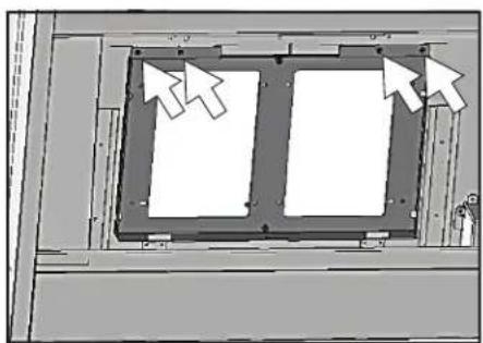
natural_image
Diagram of a mechanical assembly with two rectangular components and directional arrows indicating motion (no text or symbols)-
Remove the baffle filters and if applicable, remove the side panels. Disconnect blower plug.
-
Remove (4) screws at top of hood body attaching blower to blower plate. Remove blower from interior of hood body.
-
Remove (4) screws from interior of hood body attaching blower plate to hood body. Remove blower plate.
-
Install dual blower plate from PBD-1300B kit into hood body. Attach by (4) screws previously removed from step 3.
PBD-1300B Dual Blower Installation
natural_image
Technical illustration of a mechanical assembly with a cylindrical component and a rectangular frame (no visible text or symbols)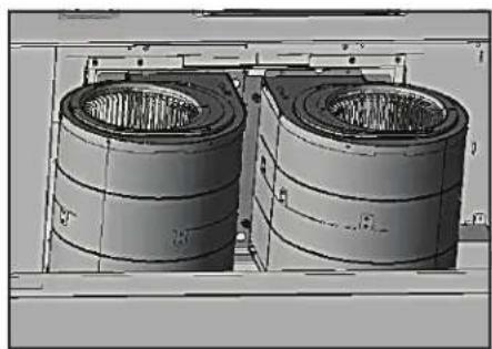
natural_image
3D rendering of two cylindrical industrial enclosures or storage tanks mounted on a platform (no visible text or symbols)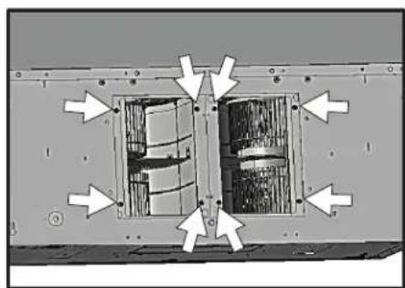
natural_image
Technical diagram of a mechanical assembly with directional arrows indicating movement or force (no text or symbols present)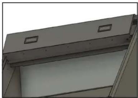
natural_image
Exterior view of a modern office building (no signage)-
Install previously removed blower onto one side of dual blower plate and attach by (4) previously removed screws from step 2.
-
Install blower from PBD-1300B kit onto other side of dual blower plate by (4) 3/16 x 3/8 screws.
-
Dual blower screw mount locations.
-
Remove (4) screws to remove the light panel. Remove the dual blower PCB from the component box. Discard the component box. Install dual blower PCB inside the hood body.
PBD-1300B Dual Blower Installation
natural_image
Abstract mechanical component diagram with no visible text or symbols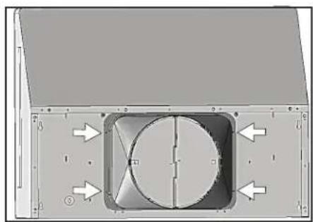
natural_image
Technical diagram of a mechanical component with directional arrows and a central circular feature (no text or symbols)-
Refer to page 32-33 section for this step. Connect the wiring from the dual blower including both blower plugs, blower cable 6 pin connector (E), dual blower switch cable (H), black single pin power cord from dual blower (K), and white single pin power cord (F) to dual blower PCB.
-
Place 10" round adapter (included with PBD-1300B) on top of hood and secure with (4) M3.5 x 8 screws.
NOTE: To secure the 10" transition adapter to top of hood a cut out of 14-1/2" width x 10-1/2" depth will need to be made in the cabinet bottom.
If internal cabinet dimensions prevent this size of a cut out then the 10" transition adapter may be mounted to the cabinet bottom rather than the top of the hood. Cut out dimensions for this type of installation are 13-1/4" width x 6-1/4" depth.
Mounting the Hood
If recirculating range hood refer to the manual included with ZRC-70xxC recirculating kit or on our website prior to installing hood.

CAUTION

At least two installers are required due to the weight and size of the hood.
- Select preferred ducting application (vertical or horizontal) and prepare hood. Remove the safety screw on top of hood body.
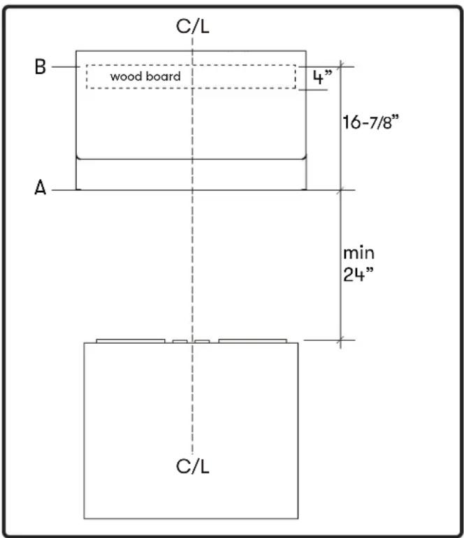
- Choose desired height above cooking surface (24" min). Level and mark hood bottom, line A (FIG. B)
- Plum and mark center line on wall.
- Level and mark top of wood board, line B (FIG. B) 16-7/8" from line A.
- Mark center line of wood board. Center and align top of board with line B. Secure wood board to studs using (4) #6 wood screws. Wood Board Dimensions: (W x D x H)
$$ 3 0": 2 7" \times 1 / 2" \times 4" $$
$$ 3 6 ^ {\prime \prime}: 3 3 ^ {\prime \prime} \times 1 / 2 ^ {\prime \prime} \times 4 ^ {\prime \prime} $$
$$ 4 8": 4 5" \times 1 / 2" \times 4" $$
text_image
C/L B wood board 4" 16-7/8" min 24" A C/LFIG. B
- Prepare duct pipe and duct cut outs in upper cabinet if needed or wall if horizontally ducting hood. Prepare electrical wiring and electrical cut outs in upper cabinet if needed or wall if horizontal electrical hook up is required. Refer to hood specifications on page 15 for dimensions.
- Mount hood onto wood board and secure using (4) #6 wood screws. Further secure hood onto wall through lower body screw holes by (2) #6 wood screws.
- Install electrical and duct work and seal with certified aluminum duct tape.
- If using RF remote control, remove baffle filters and remove the light panel by (4) screws and extend the blue antenna wire. There is no need to secure it. Reinstall light panel and baffle filters.
- Power up hood and check for leaks around duct tape.
Proximity Controls
text_image
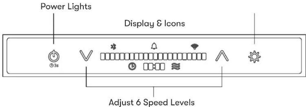
Power Lights Display & Icons Adjust 6 Speed LevelsPROXIMITY SENSOR
When approaching the hood while it is powered off, the Power, Fan Decrease, Fan Increase, and Light icons will illuminate, and "HELLO" will appear on the LCD display for 2 seconds.
If neither the fan nor lights are turned on within 60 seconds, the icons will turn off, and "GOODBYE" will appear on the LCD display for 2 seconds.
The icons will not disappear until the fan and lights are turned off.
CONTROL ICONS

Power
▶ Press the power icon to power on or off the fan and lights.
The hood has a memory function to remember the last used settings for the fan and lights.
▶ After pressing the power icon to power off the hood, "GOODBYE" will appear on the LCD display for 2 seconds.
The 3s icon under the power icon only illuminates when the fan is powered on. It is an indicator to enable Automatic Delay Off by pressing and holding the power button for 3 seconds.

Decrease Fan Speed
▶ Press the icon to decrease fan speed from 6, 5, 4, 3, 2, 1, off.

Increase Fan Speed
▶ Press the icon to increase fan speed from off, 1, 2, 3, 4, 5, 6.

Lights
▶ Press the lights icon to change lighting level from 1, 2, 3, off.
Proximity Controls
DISPLAY ICONS & FUNCTIONS

Notification Bell
The notification bell icon will illuminate when an action needs to be taken. Tapping the icon will cycle through the notifications. The notification bell will remain illuminated until all notifications are resolved. The notification bell will not illuminate when the hood and controls are powered off.

Bluetooth®
The Bluetooth® icon will illuminate the device when connected with the hood via Bluetooth®. The words “BLUETOOTH CONNECTED” or “BLUETOOTH DISCONNECT” will appear on the LCD display whenever the connection changes.

Wi-Fi
The Wi-Fi icon will illuminate when the hood is connected to the Wi-Fi. The words “WIFI CONNECTED” or “WIFI DISCONNECTED” will appear on the LCD display whenever the connection changes which will be managed via the Zephyr Connect app.

Automatic Delay Off
While the fan is on, press and hold ⏻ for 3 seconds to enable the delay off timer. The fan will change to speed 1, the timer display will illuminate, the LCD display will show “AUTOMATIC DELAY OFF”, and the timer will begin counting down from 10 minutes. After the timer reaches 0, the fan and lights will power off.
The automatic delay off function timer begins at 10 minutes by default. The Zephyr Connect app provides the options for either 5 or 10 minutes.

CleanAir
When the fan is off, press and hold √ and ∧ simultaneously for 3 seconds to enable or disable the CleanAir function. The LCD display will show “CLEAN AIR ENABLED” or “CLEAN AIR DISABLED”.
When enabled, the fan will turn on speed 1 every 4 hours for 10 minutes. While the fan is running, the LCD display will show “CLEAN AIR ACTIVE” and the CleanAir icon will illuminate.
Proximity Controls
ACT™ Verification
Airflow Control Technology (ACT™) allows the installer to set the maximum fan CFM to align with local codes and regulations. When the fan is off, press and hold ⏻ for 3 seconds to display ACT™ status.
▶ ACT 290 = 3 speeds, ACT 390 = 4 speeds, ACT 590 = 5 speeds.
Grease Filter Clean Reminder
▶ After 60 hours of fan use, the notification bell icon will illuminate. When the bell is tapped, the LCD display will cycle between showing “CLEAN GREASE FILTERS” and then “HOLD DOWN TO RESET” every 2 seconds. If no action is taken for 30 seconds, the display turns off and the notification bell icon will remain illuminated.
▶ To hold down and reset, press and hold the fan decrease button for 3 seconds to reset. The Zephyr Connect app provides the option to reset the reminder.
Recirculating Mode - Charcoal Filter Replacement Reminder
Hold ∧ and ⚙ for 3 seconds to enable or disable recirculating mode which will remind you to replace the charcoal filter. The LCD display will show “RECIRCULATING ENABLED” to enable and “RECIRCULATING DISABLE” to disable for 2 seconds.
▶ After 200 hours of fan use, the notification bell icon will illuminate. When the bell is tapped, the LCD display will cycle between showing “REPLACE CHARCOAL FLTR” and “HOLD UP TO RESET” every 2 seconds. If no action is taken for 30 seconds, the display turns off and the notification bell will remain illuminated.
▶ To hold up and reset, press and hold the fan increase button for 3 seconds to reset. The Zephyr Connect app provides the option to reset the reminder.
Remote Control Pairing Mode
Hold ⚙ for 3 seconds to enable remote control pairing mode. Once pairing mode is enabled, the LCD display will illuminate “REMOTE PAIRING”. Press a button on the remote control to synchronize it with the hood.
Zephyr Connect
Your range hood is compatible with our Zephyr Connect app. All you need is a WiFi connection with access to the Internet that can reach the location of your range hood. Zephyr Connect allows you to control your range hood from anywhere using a mobile device or your Amazon Alexa or Google Home smart speaker. Zephyr Connect also includes real time diagnostics and provides you with important product information.
The Zephyr Connect app is available on iOS devices using iOS 11.0 or later or Android devices using Android version 8 or later. Visit the Apple App Store or Google Play Store for more information.
If your range hood is not connected to WiFi, the functionality will operate similarly to a typical range hood without WiFi connectivity.
Please review the included Zephyr Connect Quick Start Guide for more information.
If you have connected your hood with either Amazon Alexa or Google Home smart speakers, you now have voice control capabilities. The list of commands for Amazon Alexa and Google Home are on the next page.
NOTE: Amazon Alexa and Google Home cannot support the voice commands in French.
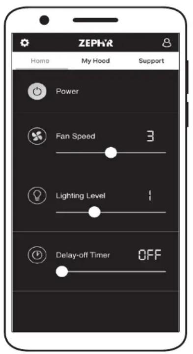
text_image
ZEPHR Home My Hood Support Power Fan Speed 3 Lighting Level 1 Delay-off Timer OFF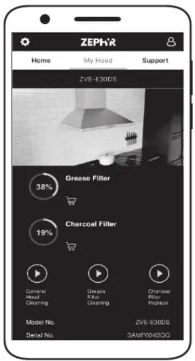
text_image
ZEPHR Home My Hood Support ZVE-E30DS Grease Filter 38% Charcoal Filter 19% General Hood Cleaning Grease Filter Cleaning Charcoal Filter Replace Model No. Serial No. ZVE-E30DS SAMP004BOQZephyr Connect
| Control Type Amazon Alexa Voice Commands Description | ||
| Power | Alexa, turn on [Hood Name] Turn on range hood power | |
| Alexa, turn off [Hood Name] Turn off range hood power | ||
| Fan | Alexa, increase [Hood Name] Fan Speed Increase fan speed on range hood | |
| Alexa, decrease [Hood Name] Fan Speed Decrease fan speed on range hood | ||
| Alexa, set [Hood Name] Fan Speed to [1-6] Set range hood to specific fan speed | ||
| Alexa, set [Hood Name] Fan Speed to Maximum Set fan speed to 6 on range hood | ||
| Alexa, set [Hood Name] Fan Speed to Minimum Set fan speed to 1 on range hood | ||
| Light | Alexa, turn on [Hood Name] Light Turn on the light on range hood | |
| Alexa, turn off [Hood Name] Light Turn off the light on range hood | ||
| Alexa, increase [Hood Name] Light(s) Increase light level on range hood | ||
| Alexa, decrease [Hood Name] Light(s) Decrease light level on range hood | ||
| Alexa, set [Hood Name] Light(s) to HighAlexa, set [Hood Name] Light(s) to Bright | Set light level to High on range hood | |
| Alexa, set [Hood Name] Light(s) to LowAlexa, set [Hood Name] Light(s) to Dim | Set light level to Low on range hood | |
| Alexa, set [Hood Name] Light(s) to [1-3] Set range hood to specific light level | ||
| Delay-Off | Alexa, set delay time to 1 minute on [Hood Name]Alexa, set delay time to 2-10 minutes on [Hood Name] | Enable delay timer for 1-10 minutes. After 1-10 minutes, the hood will be power off. |
| Alexa, [Start/Enable] [Hood Name] Delay Off Timer | Enable delay off timer for 10 minutes. After 10 minutes, the hood will power off. | |
| Alexa, [Stop/Disable] [Hood Name] Delay Off Timer | Disable delay off timer | |
| Control Type | Google Home Voice Command | Description |
| Power | Hey Google, turn on [Hood Name] | Turn on range hood power |
| Hey Google, turn off [Hood Name] | Turn off range hood power | |
| Fan | Hey Google, increase [Hood Name] speed | Increase fan speed on range hood |
| Hey Google, decrease [Hood Name] speed | Decrease fan speed on range hood | |
| Hey Google, set [Hood Name] to speed [1-6] | Set range hood to specific fan speed | |
| Hey Google, set [Hood Name] to maximum speed | Set fan speed to the maximum on range hood | |
| Hey Google, set [Hood Name] to minimum speed | Set fan speed to the minimum on range hood | |
| Light | Hey Google, turn on [Hood Name] light(s) | Turn on the light on range hood |
| Hey Google, turn off [Hood Name] light(s) | Turn off the light on range hood | |
| Hey Google, set [Hood Name] light(s) to High Hey Google, set [Hood Name] light(s) to Bright | Set light level to High on range hood | |
| Hey Google, set [Hood Name] light(s) to Low Hey Google, set [Hood Name] light(s) to Dim | Set light level to Low on range hood | |
| Hey Google, set [Hood Name] light(s) to 1-3 | Set range hood to specific light level | |
| Hey Google, Run [Hood Name] for 1-10 minutes | Enable delay timer for 1-10 minutes. After 1-10 minutes, the hood will be power off. | |
| Hey Google, Start 1-10 minute timer on [Hood Name] | Enable delay timer for 1-10 minutes. After 1-10 minutes, the hood will be power off. | |
| Delay-Off | Hey Google, Stop [Hood Name] timer | Disable delay timer |
| Hey Google, Cancel [Hood Name] timer | Disable delay timer |
Optional RF Remote Control
To order the RF remote control, the part number is 14000005. The blue antenna wire needs to be extended for optimal signal. Please refer to section, Mounting the Hood, for instructions.
FCC Caution
To assure continued compliance, any changes or modifications not expressly approved by the party responsible for compliance could void the user's authority to operate this equipment. (Example - use only shielded interface cables when connecting to computer or peripheral device. This device complies with Part 15 of the FCC Rules. Operation is subject to the following two conditions. (1) This device may not cause harmful interference, and (2) This device must accept any interference received, including interference that may cause undesired operation.
Synchronization
To create a unique link between your hood and remote control please follow these steps.
- With hood off, press and hold ⚙ on the hood until the controls display "REMOTE PAIRING".
- Press a button on the remote, and the remote control will be synchronized with the hood.
RF Remote Control Functions

text_image
Blower On/ Speed Selection Blower On/ Power Off 1 2 ZEPHYR 10 Min Delay Off 3 4 Lights 1/2/3/Off1 Blower On / Speed Selection
Press 80 to power on blower and cycle through all six blower speeds.
② Blower On / Power Off
By pressing ⏻ the blowers will power on at the last speed setting. Press 📍 again and the entire hood will power off, including lights.
③ Delay Off
By pressing ⬆, the blower and lights will enter Automatic Delay Off mode. The clock icon will illuminate and the controls will display "AUTOMATIC DELAY OFF". The blower will change to speed 1 and a 10 minute timer will begin counting down.
4 Lights 1/2/3/Off
Switch between light levels by pressing ⚙️. Turn off the lights by cycling through the different light levels.
Optional RF Remote Control
RF Remote Features
The RF remote control is equipped with a magnet on the back for easy storage. The remote may be placed on any magnetic surface such as a refrigerator or the Zephyr remote holder, FIG. C. The remote holder can be inserted into a standard electrical outlet for easy storage. Note: The remote holder does not charge the RF remote.
Maximum remote control communication distance is 15 feet from the liner.
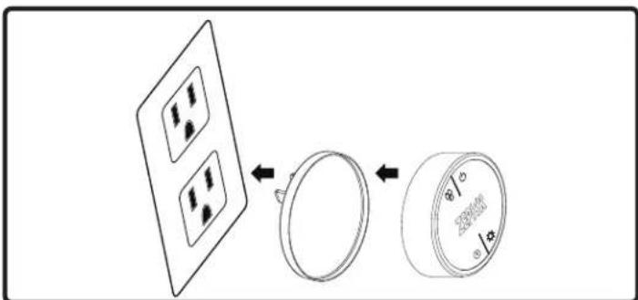
text_image
Diagram showing a device with four circular components and a magnified view of the circular dial with measurement markings.FIG. C
RF Remote Maintenance
Clean the remote control using non abrasive detergents.
Follow instructions below for replacing battery. Using a small flat head screwdriver, raise the cover of the battery door (A) in order to access the battery compartment. FIG. D.
Remove the battery and replace with battery type A23 12V. Negative end of battery should face the spring inside the remote.
Re-install battery door and recycle old battery.
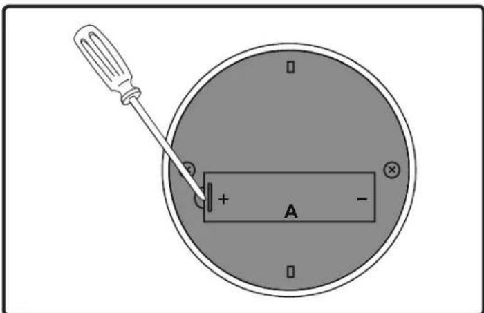
text_image
Diagram showing a screwdriver inserted into a circular device with labeled terminals and polarity indicatorsFIG. D
Hood & Filter Cleaning
Surface Maintenance
▶ Do not use corrosive detergents, abrasive detergents or oven cleaners.
▶ Do not use any product containing chlorine bleach or any product containing chloride.
▶ Do not use steel wool or abrasive scrubbing pads which will scratch and damage surface.
Cleaning Stainless Steel
Clean periodically with warm soapy water and clean cotton cloth or micro fiber cloth. Always rub in the direction of the stainless steel grain. To remove heavier grease build up use a liquid degreaser detergent.
After cleaning use a non-abrasive stainless steel polish/cleaners, to polish and buff out the stainless luster and grain. Always scrub lightly, with clean cotton cloth or micro fiber cloth and buff in the direction of the stainless steel grain.
Cleaning the Baffle Filters
The stainless steel baffle filters are intended to trap residue and grease from cooking. Although the filters should never need replacing, they are required to be cleaned every 30 days or more often depending on cooking habits.
Filters may be placed in dishwasher at low heat or soaked in hot soapy water Dry filters and re-install before using hood.
Removing Baffle Filters, FIG. E
- Push filter toward front of range hood using handles.
- Pivot back of filter downward.
- Remove filter by pulling away from hood.
Replacing Baffle Filters
| Hood Model Part Number Qty. to | Order | |
| AK7400AS 50210039 2 | ||
| AK7436AS 50210039 2 | ||
| AK7448AS 50210039 2 | ||
Recirculating Kit
(includes charcoal filters and air diverter)
| Hood Model Part Number Qty. to | Order |
| AK7400AS ZRC-7000C 1 | |
| AK7436AS ZRC-7036C 1 | |
| AK7448AS ZRC-7048C 1 |
Replacement Charcoal Filters also available by ordering part number Z0F-C002.
See manual included with recirculating kit for more information.
To order parts, visit us online at http://store.zephyronline.com.
flowchart
graph TD
    A["Step 1"] --> B["Step 2"]
    B --> C["Step 3"]
FIG. E
LumiLight LED
In the unlikely event that your LumiLight LED fails, please contact Zephyr to order replacement parts.
See the list of parts and accessories page for part numbers and contact information.
LED Removal (FIG. F):
-
Remove pro baffle filters.
-
(If applicable) Remove both spacer panels by 2 screws for each spacer panel.
-
Remove light panel by 4 screws.
-
Disconnect LED light quick connector.
-
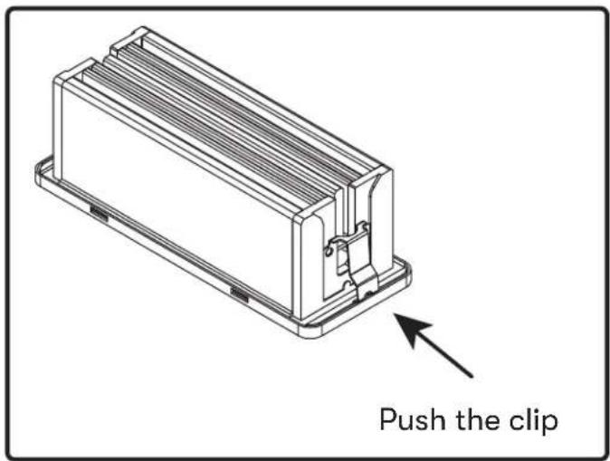
Push in the two side clips on the ends of the LED light.
-
Push LED light through the light panel opening.
text_image
Push the clipFIG. F
Airflow Control Technology (ACT™)
Some local codes limit the maximum amount of CFM a range hood can move. ACT ^™ allows you to control the maximum blower CFM of select Zephyr Ventilation range hoods without the need for expensive make up air kits. ACT ^™ enables the installer to easily set the maximum blower speed to one of two most commonly specified CFM levels; 590, 390, or 290 CFM. The usage of ACT ^™ may not be necessary for your installation. Please check your local codes for CFM restrictions.
ACT ^™ is not available with 1300 CFM dual internal blower option.

CAUTION

Hood must be disconnected from the main power prior to performing the conversion instructions listed below. Failure to do so could result in personal injury or damage to the product.

CAUTION

After re-positioning the jumper and powering on the hood, the CFM cannot be changed again.
Enabling ACT™
To enable ACT™:
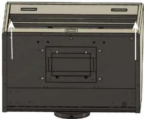
- Before hood installation, gain access to PC board by following the steps shown on FIG. J.
- Change plastic jumper positioning as shown in FIG. K to set the desired maximum blower CFM.
- Re-install PC board and continue with hood installation.
- Remove the appropriate foil CFM sticker included with the hood literature and place inside the hood body below the wiring diagram or in another clearly visible location.
To verify if your installer enabled ACT™:
- With hood off, hold the On/Off button for three seconds. The Display will show if ACT ^™ is disabled and set to the maximum CFM or if ACT ^™ is enabled and set to one of the restricted maximum CFM levels of 590, 390 or 290.
- There should also be a foil label located inside the hood body near the wiring diagram that indicates the blower CFM.
Enabling ACT™
- PC board located behind the light panel.
- (If applicable) Remove both spacer panels by
2 screws for each spacer panel. - Remove 4 screws attaching light panel.
natural_image
Diagram of a computer monitor with an open panel and internal components, showing no text or symbols.FIG. J
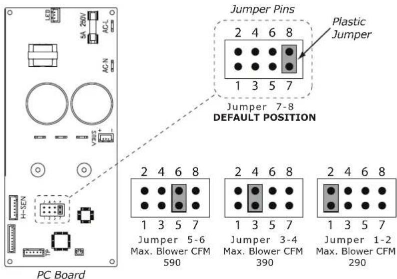
text_image
Jumper Pins Plastic Jumper 2 4 6 8 1 3 5 7 Jumper 7-8 DEFAULT POSITION 2 4 6 8 1 3 5 7 Jumper 5-6 Max. Blower CFM 590 Jumper 3-4 Max. Blower CFM 390 Jumper 1-2 Max. Blower CFM 290 PC BoardFIG. K
Single Blower

text_image
AK7400AS and AK7436AS Wiring Diagram Green White Black Body Black Red White Black Green Body Black Motor ANT S1 LED LED WIFIDual Blower
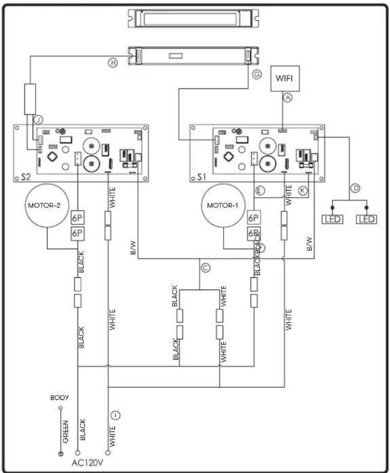
text_image
S2 MOTOR-2 6P 6P BLACK WHITE B/W BODY GREEN BLACK AC120V ① WHITE WIFI S1 MOTOR-1 6P 6P BLACK WHITE B/W ② LED LED WHITE BLACK WHITE WHITEA. Wi-Fi connection wire
C. Power wire for expansion PCB
D. Power wire for expansion PCB
E. Blower connection wire
F. Blower connection wire
G. Control connection wire
H. Dual blower PCB to switch wire
I. Power lead
J. Dual blower connection wire
K. Blower connection wire
Single Blower
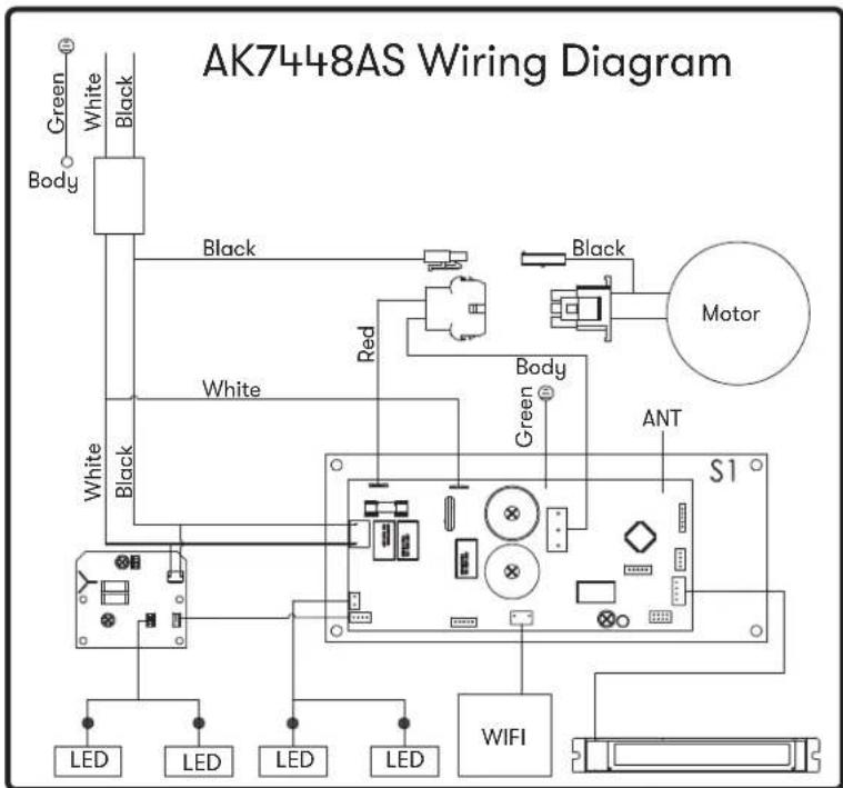
text_image
AK7448AS Wiring Diagram Green White Black Body Black White Black Red Black Motor White Body Green ANT S1 LED LED LED LED WIFIDual Blower
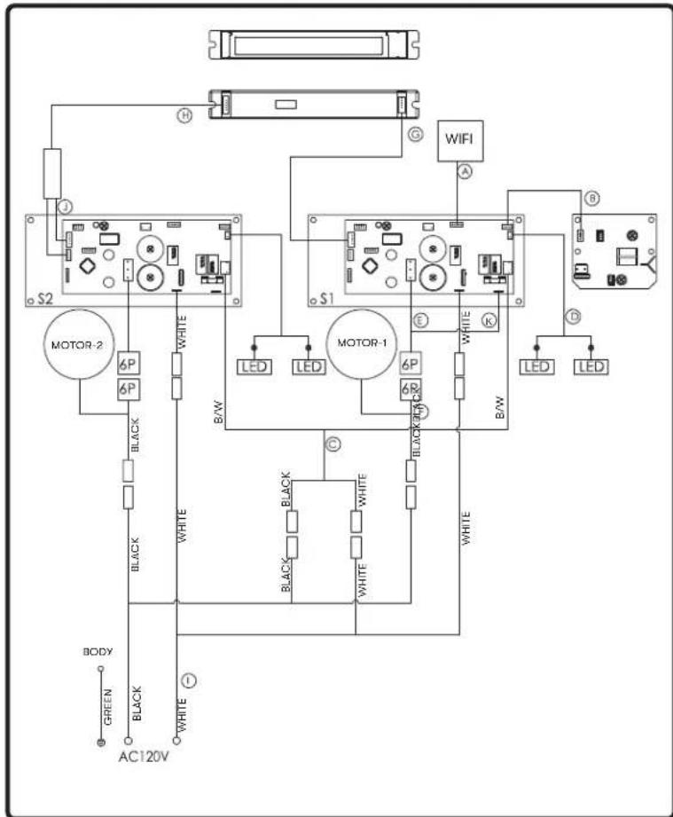
text_image
S2 MOTOR-2 6P BLACK WHITE B/W BODY GREEN BLACK WHITE AC120V G WIFI A S1 MOTOR-1 6P BLACK WHITE B/W C BLACK WHITE WHITE B LED LED LED LED S1 K E WHITE B/W B WHITEA. Wi-Fi connection wire
B. LED PCB wire
C. Power wire for expansion PCB
D. Power wire for expansion PCB
E. Blower connection wire
F. Blower connection wire
G. Control connection wire
H. Dual blower PCB to switch wire
- Power lead
J. Dual blower connection wire
K. Blower connection wire
Possible Problem Possible Cause Solutions
| After installation, the unit doesn't work. | The power source is not turned ON. Make sure the circuit breaker and the unit's power is ON. | |||
| The power line and the cable locking connector is not connecting properly. | Check the power connection with the unit is connected properly. | |||
| The switch board or control board wirings are disconnected. | Make sure the wirings at the switch board and control board are connected properly. | |||
| The switch board or control board is defective. | Change the switch board or control board. | |||
| The wires on control board are loose. | Make sure the wires on the control board are connected properly. | |||
| Light works, but blower is not turning. | The blower wire is not connected. Make sure the blower wire is plugged into the molex connector. | |||
| The thermally protected system detects if the blower is too hot to operate and shuts the blower down. | The blower will function properly after the thermally protected system cool down. | |||
| Damaged capacitor. Change the capacitor. | ||||
| Blower molex plug pin is not making contact. | Disconnect the blower molex plug, check pins inside plug to see if pin is pushed inside the plug too far. Reset pin if needed. | |||
| The blower is defective, possibly seized. | Change the blower. | |||
| The unit is vibrating. The | blower is not secured in place. Tighten the blower in place. | |||
| Damaged blower wheel. Replace the blower. | ||||
| The hood is not secured in place. Check the installation of the hood. | ||||
| The unit is whistling. A filter is not in the correct position. Adjust the filters until the whistling stops. | ||||
| The duct pipe connections are not sealed or connected properly. | Check the duct pipe connections to be sure all connections are sealed properly. | |||
| The blower is working, but the LumiLight LEDs are not. | The LumiLight LED connector is disconnected. | Connect the LumiLight LED connector. | ||
| Defective LumiLight LED. | Change the LumiLight LED. | |||
| The switch board or control board is defective. | Change the switch board or control board. | |||
| Possible Problem Possible Cause Solutions | ||||
| The hood is not venting out properly. | Using the wrong size of ducting. Change the ducting to the correct size. | |||
| The hood might be hanging to high from the cook top. | Adjust the distance between the cook top and the bottom of the hood within 24" and 34" range. | |||
| The wind from the opened windows or opened doors in the surrounding area are affecting the ventilation of the hood. | Close all the windows and doors to eliminate the outside wind flow. | |||
| Blockage in the duct opening or ductwork. | Remove all the blocking from the duct work or duct opening. | |||
| The unit turns on by itself. | Remote control may be paired incorrectly. | Resynchronize the remote control to connect to a different channel | ||
| Someone is controlling the hood via the Zephyr Connect app. | Determine who is controlling the hood with the app. | |||
| Filter is vibrating. Filter is | loose. Adjust or change the filter. | |||
| Spring clip is broken on the filter. Change the spring clip. | ||||
| RF Remote control does not work. | Battery is dead. Replace battery with type A23 12v. | |||
| Poor communication with the hood. Remote control must be within 15 ft of hood. | ||||
| RF Remote lost communication with the hood. | Reset hood and remote by switching power off at the circuit breaker for 5 minutes. Place remote on counter top near the hood and switch the circuit breaker back on. | |||
| Blue antenna wire is not extended. Extend the blue antenna wire behind the light panel. | ||||
| The range hood and user's device won't pair via Bluetooth®. | The user's phone does not have Bluetooth® enabled. | Enable Bluetooth® on the user's phone. | ||
| The user's phone may be out of range. | Move closer towards the range hood. | |||
| User hasn't inputted the Bluetooth® code to successfully pair. | Enter the pairing code, 123456. | |||
| Range hood is not in Bluetooth® pairing mode. | Hold √ and ⚙imultaneously for 5 seconds to put the hood into pairing mode. | |||
| There are multiple errors preventing the user's phone from pairing with the range hood. | Restart the user's phone and try again. | |||
| The range hood won't connect to Wi-Fi. | The user's router or modem is turned off. | Turn on the router or modem. | ||
| The user's router is connected to a 5 GHz wireless frequency. | Connect to the 2.4 GHz band and attempt to reconnect. | |||
| The user's coaxial cables are loose. Tighten the coaxial cables connecting to the router or modem. | ||||
| The Wi-Fi on the user's phone is disabled. | Enable Wi-Fi on the phone. | |||
| User is connecting to the wrong Wi-Fi network. | Verify that the correct Wi-Fi network is being connected to. The default Wi-Fi network name/SSID can be found on the router. | |||
| The range hood is not in range of the Wi-Fi connection. | Move the router and modem closer to the range hood to increase connection strength. | |||
| There are obstacles obstructing the Wi-Fi signal strength. | Move the router and modem closer to the range hood or move objects that are directly blocking the pathway to the range hood. Walls may reduce signal strength. | |||
| User cannot change Wi-Fi connections. | The range hood and user's phone have already connected. | Enter Bluetooth® settings and forget the device to reset the process on the phone. | ||
| Cannot bind the hood to my Zephyr Connect account. | Only one Zephyr Connect account can be bound to the hood. | Log in using the Zephyr Connect account that is already bound to the hood. Multiple devices can login using the same account. | ||
| Zephyr Connect app won't register user inputs. | Wi-Fi is unstable and the range hood may have disconnected. | Ensure the router and modem are both turned on. Allow the range hood to reconnect. | ||
| Range hood is experiencing difficulties connecting to the user's phone. | Check on the Wi-Fi connection and restart the application. | |||
| Zephyr Connect app stuck on “Loading”. | Wi-Fi is unstable and the range hood may have disconnected. | Ensure the router and modem are both turned on. Allow the range hood to reconnect. | ||
| Range hood is experiencing difficulties connecting to the user's phone. | Check on the Wi-Fi connection and restart the application. | |||
| Description Part Number | |
| Replacement Parts | |
| LumiLight LED, 6W Z0B0048 | |
| Pro Baffle Filter (each) 50210039 | |
| Optional Accessories | |
| Dual Internal Blower PBD-1300B | |
| Make-up Air Kit (Single Blower) MUA008A | |
| Make-up Air Kit (Dual Blower) MUA010A | |
| RF Remote Control 14000005 | |
| Duct Cover 30” x 12” AK0720 | |
| Duct Cover 36” x 12” AK0726 | |
| Duct Cover 48” x 12” AK0728 | |
| Duct Cover 30” x 24” AK1720 | |
| Duct Cover 36” x 24” AK1726 | |
| Duct Cover 48” x 24” AK1728 | |
To order parts, visit us online at http://store.zephyronline.com.
Notes
PRO
TIDAL II
WALL
TO OBTAIN SERVICE UNDER WARRANTY OR FOR ANY SERVICE RELATED QUESTIONS
United States Customers please call: 1-888-880-8368 or contact us at: zephyronline.com/contact
Canada Customers please call: 1-800-361-0799 or Email: service@distinctive-online.com
Zephyr Ventilation, LLC (referred to herein as “we” or “us”) warrants to the original consumer purchaser (referred to herein as “you” or “your”) of Zephyr products (the “Products”) that such Products will be free from defects in materials or workmanship as follows:
Three Year Limited Warranty for Parts: For three years from the date of your original purchase of the Products, we will provide, free of charge, Products or parts (including LED light bulbs, if applicable) to replace those that failed due to manufacturing defects subject to the exclusions and limitations below. We may choose, in our sole discretion, to repair or replace parts before we elect to replace the Products.
One Year Limited Warranty for Labor: For one year from the date of your original purchase of the Products, we will provide, free of charge, the labor cost associated with repairing the Products or parts to replace those that failed due to manufacturing defects subject to the exclusions and limitations below. After the first year from the date of your original purchase, you are responsible for all labor costs associated with this warranty.
Warranty Exclusions: This warranty covers only repair or replacement, at our option, of defective Products or parts and does not cover any other costs related to the Products including but not limited to: (a) normal maintenance and service required for the Products and consumable parts such as fluorescent, incandescent or halogen light bulbs, mesh and charcoal filters and fuses; (b) any Products or parts which have been subject to freight damage, misuse, negligence, accident, faulty installation or installation contrary to recommended installation instructions, improper maintenance or repair (other than by us); (c) commercial or government use of the Products or use otherwise inconsistent with its intended purpose; (d) natural wear of the finish of the Products or wear caused by improper maintenance, use of corrosive and abrasive cleaning products, pads, and oven cleaner products; (e) chips, dents or cracks caused by abuse or misuse of the Products; (f) service trips to your home to teach you how to use the Products; (g) damage to the Products caused by accident, fire, floods, acts of God; or (h) Custom installations or alterations that impact serviceability of the Products. If you are outside our service area, additional charges may apply for shipping costs for warranty repair at our designated service locations and for the travel cost to have a service technician come to your home to repair, remove or reinstall the Products. After the first year from the date of your original purchase, you are also responsible for all labor costs associated with this warranty. All Products must be installed by a qualified professional installer to be eligible for warranty repairs or service.
Limitations of Warranty. OUR OBLIGATION TO REPAIR OR REPLACE, AT OUR OPTION, SHALL BE YOUR SOLE AND EXCLUSIVE REMEDY UNDER THIS WARRANTY. WE SHALL NOT BE LIABLE FOR INCIDENTAL, CONSEQUENTIAL OR SPECIAL DAMAGES ARISING OUT OF OR IN CONNECTION WITH THE USE OR PERFORMANCE OF THE PRODUCTS. THE EXPRESS WARRANTIES IN THE PRECEDING SECTION ARE EXCLUSIVE AND IN LIEU OF ALL OTHER EXPRESS WARRANTIES. WE HEREBY DISCLAIM AND EXCLUDE ALL OTHER EXPRESS WARRANTIES FOR THE PRODUCTS, AND DISCLAIM AND EXCLUDE ALL WARRANTIES IMPLIED BY LAW, INCLUDING THOSE OF MERCHANTABILITY AND FITNESS FOR A PARTICULAR PURPOSE.
Some states or provinces do not allow limitations on the duration of an implied warranty or the exclusion or limitation of incidental or consequential damages, so the above limitations or exclusions may not apply to you. To the extent that applicable law prohibits the exclusion of implied warranties, the duration of any applicable implied warranty is limited to the same three-year and one-year periods described above if permitted by applicable law. Any oral or written description of the Products is for the sole purpose of identifying the Products and shall not be construed as an express warranty. Prior to using, implementing or permitting use of the Products, you shall determine the suitability of the Products for the intended use, and you shall assume all risk and liability whatsoever in connection with such determination. We reserve the right to use functionally equivalent refurbished or reconditioned parts or Products as warranty replacements or as part of warranty service. This warranty is not transferable from the original purchaser and only applies to the consumer residence where the Product was originally installed located in the United States and Canada. This warranty is not extended to resellers.
To Obtain Service Under Limited Warranty: To qualify for warranty service, you must: (a) notify us at the address or telephone number stated below within 60 days of the discovery of the defect; (b) give the model number and serial number; and (c) describe the nature of any defect in the Product or part. At the time of the request for warranty service, you must present evidence of your proof of purchase and proof of the original purchase date. If we determine that the warranty exclusions listed above apply or if you fail to provide the necessary documentation to obtain service, you will be responsible for all shipping, travel, labor and other costs related to the services. This warranty is not extended or restarted upon warranty repair or replacements.
Please check our website for any additional Product information, www.zephyronline.com
Zephyr, 2277 Harbor Bay Parkway, Alameda, CA 94502
JAN21.0501
Congratulations on the purchase of your Zephyr product! Please take a moment to register your new Zephyr product at www.zephyronline.com/registration
IT'S IMPORTANT
Prompt registration helps in more ways than one.
- Ensures warranty coverage should you need service.
- Ownership verification for insurance purposes.
- Notification of product changes or recalls.

text_image
STOPZephyr Ventilation | 2277 Harbor Bay Pkwy. | Alameda, CA 94502 | 1.888.880.8368
Tidal II
AK7400AS, AK7436AS, AK7448AS
EN Use, Care, and Installation Guide
natural_image
Isometric line drawing of a technical enclosure or fan assembly with mounting flanges and a central circular component (no text or symbols)
Zephyr Connect

Airflow Control Technology

* National Fire Protection Association Batterymarch Park, Quincy, Massachusetts 02269
** CSA International 8501 East Pleasant Valley Road, Cleveland, Ohio 44131-5575
natural_image
Simple line drawing of a plug with a black terminal and three wires (no text or symbols)Raccord de câble
natural_image
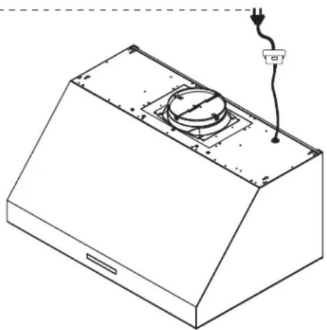
Isometric line drawing of a kitchen chimney with a mounted power outlet (no text or symbols)FIG. A
natural_image
Illustration of a mechanical device inside a container with an arrow pointing to a component (no text or symbols visible)natural_image
Technical diagram of a mechanical assembly with directional arrows indicating motion or force directions (no text or symbols present)natural_image
Mechanical assembly diagram showing two views of a gear assembly with no visible text or symbolsnatural_image
Mechanical assembly diagram showing a cylindrical component mounted on a frame with directional arrows indicating motion (no text or symbols present)natural_image
Technical diagram showing two views of a mechanical component with directional arrows indicating movement (no text or symbols present)natural_image
Interior view of a technical enclosure with directional arrows indicating movement or flow (no text or symbols present)natural_image
Illustration of a mechanical device inside a chamber with an arrow pointing to a component (no text or symbols present)natural_image
Close-up of a mechanical component with a highlighted circular feature and an arrow pointing to it (no text or symbols visible)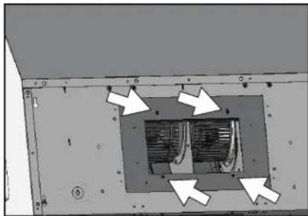
natural_image
Interior view of a room with a central air vent and directional arrows indicating flow or movement (no text or symbols present)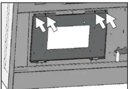
natural_image
Diagram of a mechanical component with arrows pointing to a rectangular housing (no text or symbols)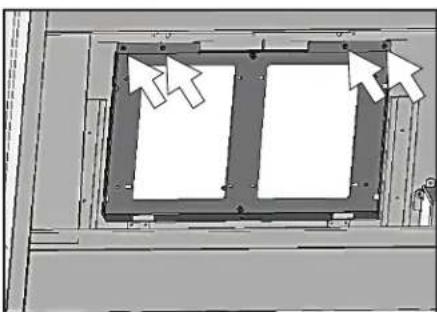
natural_image
Diagram of a mechanical assembly with two rectangular components and directional arrows indicating movement (no text or symbols)natural_image
Technical illustration of a mechanical assembly with a cylindrical component and a rectangular frame (no visible text or symbols)natural_image
3D rendering of two cylindrical industrial enclosures mounted on a platform (no visible text or symbols)natural_image
Technical diagram of a mechanical assembly with directional arrows indicating movement or force (no text or symbols present)natural_image
Exterior view of a modern office building (no signage)natural_image
Illustration of a mechanical gear assembly inside a vehicle (no text or symbols visible)natural_image
Technical diagram of a mechanical component with directional arrows indicating movement or force (no text or symbols present)text_image
ZEPHR Home My Hood Support Power Fan Speed 3 Lighting Level Delay-off Timer OFF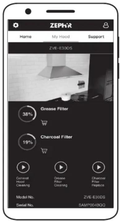
text_image
ZEPHR Home My Hood Support ZVE-E30DS Grease Filter 38% Charcoal Filter 19% General Hood Cleaning Grease Filter Cleaning Charcoal Filter Heptace Model No. ZVE-E30DS Serial No. SAMP004BQGZephyr Connect
text_image
Diagram showing a device with four circular components and a magnified view of a circular component labeled '20000'.FIG. C
text_image
Diagram showing a screwdriver inserted into a circular device with labeled terminals and polarity indicatorsFIG. D
text_image
WIFI S2 MOTEUR-2 6P 6P NOIR NOIR BLANC BLANC/NOIR MOTEUR-1 6P 6P NOIR BLANC BLANC/NOIR E K B LED LED LED LED CORPS VERT NOIR AC120V IA. Fil de connexion Wi-Fi
POUR OBTENIR UN SERVICE SOUS GARANTIE OU POUR TOUTE QUESTIONS LIÉES AU SERVICE
Zephyr, 2277 Harbor Bay Parkway, Alameda, CA 94502
JAN21.0601
www.zephyronline.com/registration