
E 435 A - Speaker HK AUDIO - Free user manual and instructions
Find the device manual for free E 435 A HK AUDIO in PDF.
| Product Type | Professional active loudspeaker (wall-mount installation kit) |
| Brand | HK Audio |
| Model | E 435 A (Active Install Kit) |
| Component Units | 1 EA 600 IL amplifier module + 1 lower E 435 IL mid/high module + 1 upper E 435 IL module + wall brackets |
| Amplifier Power | 600 W RMS at 4 ohms (Class D) |
| Speaker Module Power | 150 W RMS (nominal load) |
| Frequency Response (-10 dB) | 140 Hz – 20 kHz |
| Sensitivity (1 W / 1 m) | 97 dB (half space) |
| Nominal Impedance Module | 16 ohms |
| Speakers | 4 × 3.5" full-range |
| Directivity | 70° horizontal |
| Cutoff Frequency | 140 Hz, 12 dB/octave, passive |
| Amplifier Connections | Combo XLR/balanced jack input, Through XLR output, Speakon NL4 speaker output, E-Connect output |
| Power Supply | Mains 230 V~ (V-Lock locking connector) |
| Total Kit Weight (amplifier + 2 modules + brackets) | Approx. 7.85 kg (amplifier 2.75 kg + module 2.35 kg × 2) |
| Dimensions (full kit, height) | 848 mm (Install Kit only), up to 2376 mm with 4 modules |
| Built-in Protections | RMS limiter, DC protection, impedance protection, thermal protection, subsonic filter |
| Cooling | Thermostatically controlled fan |
| Input Sensitivity (switchable) | +4 dBu / -10 dBu |
| Mounting | Wall mounting only, brackets included, orientation +/- 90° horizontal |
| Maintenance | Clean with a dry cloth; do not open; entrust repairs to a qualified specialist |
| Safety | Do not expose to water or moisture; follow assembly and operating instructions |
Frequently Asked Questions - E 435 A HK AUDIO
User questions about E 435 A HK AUDIO
0 question about this device. Answer the ones you know or ask your own.
Ask a new question about this device
Download the instructions for your Speaker in PDF format for free! Find your manual E 435 A - HK AUDIO and take your electronic device back in hand. On this page are published all the documents necessary for the use of your device. E 435 A by HK AUDIO.
USER MANUAL E 435 A HK AUDIO
Instruction Sheet 1.2
- English
- Deutsch
- Français
Italiano - Espanol
Install Kit E 435
passive
11
E 435 IL-O
Mid/High Unit
10
E 435 IL-U
Mid/High Unit
5
3
Install Kit E 435 A
self powered
12
EA 600 IL
Power Amp
10
E 435 IL-U
Mid/High Unit
5
3
1
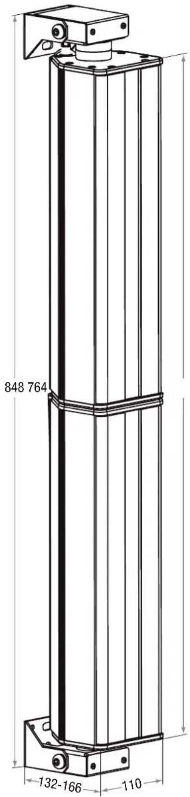
Measures in mms
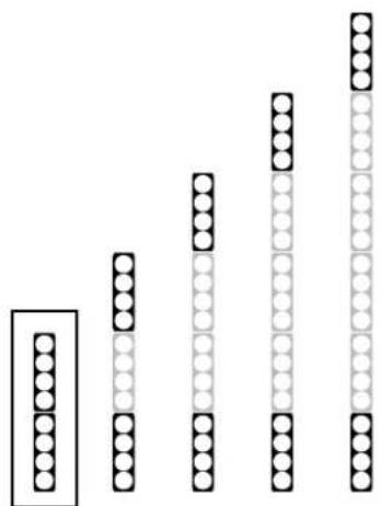
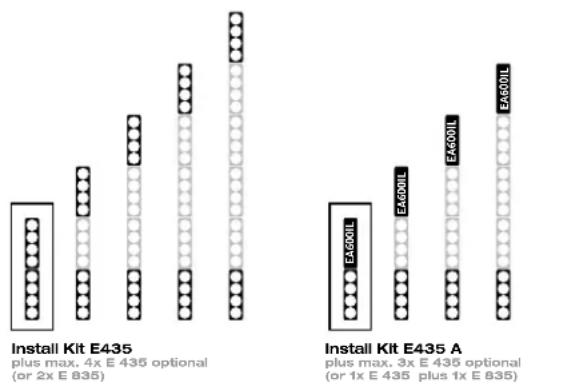
Install Kit Column Configurations
Install Kit E435 plus max. 4x E 435 optional (or 2x E 835)
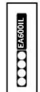
EAG00IL
EA600IL
EA600IL
Install Kit E435 A plus max. 3x E 435 optional (or 1x E 435 plus 1x E 835)
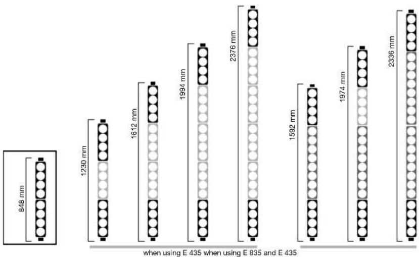
Install Kit Column Dimensions (incl. wall brackets)
Important Safety Instructions! Read before connecting!
This product has been built by the manufacturer in accordance with IEC 60065 and left the factory in safe working order. To maintain this condition and ensure non-risk operation, the user must follow the advice and warning comments found in the operating instructions. If this product shall be used in vehicles, ships or aircraft or at altitudes exceeding 2000m above sea level, take care of the relevant safety regulations which may exceed the IEC 60065 requirements.
WARNING: To prevent the risk of fire and shock hazard, do not expose this appliance to moisture or rain. Do not open case - no user serviceable parts inside. Refer service to qualified service personnel.

This symbol, wherever it appears, alerts you to the
presence of uninsulated dangerous voltage inside the enclosure - voltage that may be sufficient to constitute a risk of shock.

This symbol, wherever it appears, alerts you to the
presence of externally accessible hazardous voltage. External wiring connected to any terminal marked with this symbol must be a "ready made cable" complying with the manufacturers recommendations, or must be a wiring installed by instructed persons only.

This symbol, wherever it appears, alerts you to Important
operating and maintenance instructions in the accompanying literature. Read the manual.

This symbol, wherever it appears, tells you: Take care!
Hot surface! To prevent burns you must not touch.
- Read these instructions.
- Keep these instructions.
- Follow all warnings and instructions marked on the product and in this manual.
- Do not use this product near water. Do not place the product near water, baths, wash basins, kitchen sinks, wet areas, swimming pools or damp rooms.
- Do not place objects containing liquid on the product - vases, glasses, bottles etc.
Clean only with dry cloth. - Do not remove any covers or sections of the housing.
- The set operating voltage of the product must match the local mains supply voltage. If you are not sure of the type of power available consult your dealer or local power company.
- To reduce the risk of electrical shock, the grounding of this product must be maintained. Use only the power supply cord provided with this product, and maintain the function of the center (grounding) pin of the mains connection at any time. Make sure the mains outlet used provides a proper protective ground connection.
- Protect the power cord from being walked on or pinched particularly at plugs, convenience receptacles, and the point where they exit from the device! Power supply cords should always be handled carefully. Periodically check cords for cuts or sign of stress, especially at the plug and the point where the cord exits the device.
- Never use a damaged power cord.
- Unplug this product during lightning storms or when unused for long periods of time.
- This product can be fully disconnected from mains only by pulling the mains plug at the unit or the wall socket. The product must be placed in such a way at any time, that disconnecting from mains is easily possible.
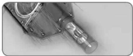
Fuses: Replace with IEC127 (5x20mm) type and rated fuse for best performance only! It is prohibited to use "patched fuses" or to short the fuse-holder. Replacing any kind of fuses must only be carried out by qualified service personal.
Refer all servicing to qualified service personnel. Servicing is required when the unit has been damaged in any way, such as: - When the power cord or plug is damaged or frayed.
- If liquid has been spilled or objects have fallen into the product.
- If the product has been exposed to rain or moisture.
- If the product does not operate normally when the operating instructions are followed.
- If the product has been dropped or the cabinet has been damaged.
- Do not connect external speakers to this product with an impedance lower than the rated impedance given on the product or in this manual. Use only cables with sufficient cross section according to the local safety regulations.
-
Keep away from direct sunlight.
-
Do not Install near heat sources such as radiators, heat registers, stoves or other devices that produce heat.
- Do not block any ventilation openings. Install in accordance with manufacturer's instructions. This product must not be placed in a built-in installation such as a rack unless proper ventilation is provided.
- Always allow a cold device to warm up to ambient temperature, when being moved into a room. Condensation can form inside it and damage the product, when being used without warming up.
- Do not place naked flame sources, such as lighted candles on the product.
- The device must be positioned at least 20cm / 8 away from walls.
- Use only with the cart, stand, tripod, bracket or table specified by the manufacturer or sold with the product. When a cart is used, use caution when moving the cart/product combination to avoid injury from tip-over.
- Use only accessories recommended by the manufacturer, this applies for all kind of accessories, for example protective covers, transport bags, stands, wall or ceiling mounting equipment. In case of attaching any kind of accessories to the product, always follow the instructions for use, provided by the manufacturer. Never use fixing points on the product other than specified by the manufacturer.
- This appliance is NOT suitable to be used by any person or persons (including children) with limited physical, sensorial or mental ability, or by persons with insufficient experience and/or knowledge to operate such an appliance. Children under 4 years of age must be kept away from this appliance at all times.
- Never push objects of any kind into this product through cabinet slots as they may touch dangerous voltage points or short out parts that could result in risk of fire or electric shock.
- This product is capable of delivering sound pressure levels in excess of 90 dB, which may cause permanent hearing damage! Exposure to extremely high noise levels may cause a permanent hearing loss. Wear hearing protection if continuously exposed to such high levels.
- The manufacturer only guarantees the safety, reliability and efficiency of this product if:
Assembly, extension, re-adjustment, modifications or repairs are carried out by the manufacturer or by persons authorized to do so.
- The electrical installation of the relevant area complies with the requirements of IEC (ANSI) specifications.
- The unit is used in accordance with the operating instructions.
- This product is optimized for use with music and speech signals. Using this product with sine wave, square wave or other kind of measuring signals at higher level may lead to severe damage of the product.
General Notes on Safety for Loudspeaker
Systems

Mounting systems may only be used for those loudspeaker systems authorized by the manufacturer and only with the existing accessories specified by the manufacturer in the installation instructions. Read and heed the manufacturer's installation instructions. The indicated load-bearing capacity is not guaranteed and the manufacturer will not be liable for damages in the event of improper installation or the use of unthorized mounting accessories.
The system's load-bearing capacity cannot be guaranteed and the manufacturer will not be liable for damages in the event that loudspeakers, mounting accessories, and connecting and attaching components are modified in any way.
Components affecting safety may only be repaired by the manufacturer or authorized agents, otherwise the operating permit will be voided.
Installation may be performed qualified personnel only, and then only at pick-points with sufficient load-carrying capacity and in compliance with local building regulations. Use only the mounting hardware specified by the manufacturer in the installation instructions (screws, anchors, etc.). Take all the precautions necessary to ensure bolted connections and other threaded locking devices will not loosen.

Fixed and portable installations (in this case, speakers and folding accessories) must be secured by two independent ties to prevent them from falling. Safeties must be able to access accessories or parts that are loose or may become loose. The compliance with the given national regulations when connecting, attaching, and rigging devices. Factor potential electric forces (jerk) into the equation when determining the motor size and load-bearing capacity of safeties.
Be sure to observe speaker stands' maximum load-bearing capacity. Note that for reasons of design and construction, most speaker stands are approved to bear centric loads only; that is, the speakers' mass has to be precisely centered and balanced. Ensure speaker stands are set up stably and securely. Take appropriate added measures to secure speaker stands, for example when:
- the floor or ground surface does not provide a stable, secure base.
- they are extended to heights that impede stability.
- high wind pressure may be expected.
- there is the risk that they may be knocked over by people. Special measures may become necessary as precautions against unsafe audience behavior. Do not set up speaker stands in evacuation routes and emergency exils. Ensure corridors are wide enough and put proper barriers and markings in place when setting speaker stands up in passageways. Mounting and dismounting are especially hazardous tasks. Use aids suitable for this purpose. Observe the given national regulations when doing so.

Wear proper protection (in particular, a helmet, gloves, and shoes) and use only suitable means of ascent (ladders, lifts, etc.) during installation. Compliance with this element is the sole responsibility of the company performing installation.

WARNING
After installation, inspect the system comprised of the mounting fixtures and loudspeakers to ensure it is properly secured. The operator of loudspeaker systems (fixed or portable) must regularly inspect or task a third party to regularly inspect all system components in accordance with the given country's regulations and have possible defects repaired immediately. We also strongly recommend maintaining a logbook or the like to document all inspections.
When installing speakers for longer lasting or permanent outdoor operation, be sure to take into account the stability and load-bearing capacity of platforms and surfaces; loads and forces exerted by wind, snow, and ice; as well as thermal influences. Also be sure to provide sufficient safety margins for the rigging points used for flow systems. Observe the given national regulations when doing so.
- Ask the manufacturer if your product is allowed for outdoor usage!

Professional loudspeaker systems can produce harmful noise levels. Even prolonged exposure to seemingly harmless (starting at about 95 dBA SPL) can cause permanent hearing damage! Therefore we recommend that everyone who is exposed to high volume levels produced by loudspeaker systems be professional hearing protection (earplugs or earmuffs).
Manufacturer: Stamer Musikanlagen GmbH, Magdeburger Str. 8, 66606 St. Wendel, Germany
1 General Information
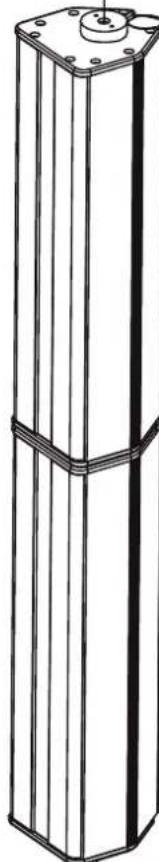
The two E 435 and E 435 A ELEMENTS INSTALL KITs consist of ELEMENT modules that have been modified for installation. Wall mounts are included. The INSTALL KIT may be extended with standard ELEMENTS E 435 and E 835 mid/high units. The mounting fixture lets you aim the speakers horizontally at any angle +/-90°.
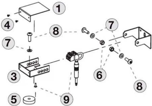
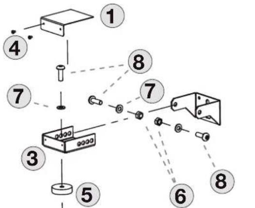
1.1. Inventory
The table below lists the parts that come with the ELEMENTS INSTALL KIT for passive and active ELEMENT modules:
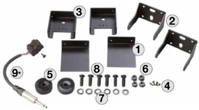
| Item no. | Name Quantity | |
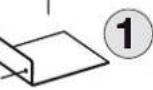
| 1 Cover plate 2 | ||
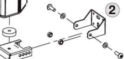
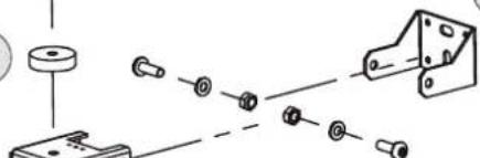
| 2 Mounting bracket 2 | ||
| 3 Retaining plate 2 | ||
| 4 M3 screws 4 | ||
| 5 Spacer sleeve 2 | ||
| 6 Locknut 4 | ||
| 7 Washers 6 | ||
| 8 M8 bolt 6 | ||
| 9* Terminal block with \( 1/4^u \) (6.3 mm) jack plug + 3.5 mm x 13 mm screw * | 1 | |
| 10 | ELEMENTS E 435 IL-U (pictured on page 2) | 1 |
| 11* | ELEMENTS E435 IL-O (pictured on page 2) | 1 |
| 12** | ELEMENTS EA 600 IL (pictured on page 2) | 1 |
) in Install Kit for passive units only *) in Install Kit for active units only
1.2 Application
The ELEMENTS INSTALL KIT is designed for one purpose only - attaching Elements components to a wall. It is the responsibility of the person installing the units to ensure the given walls and selected pickpoints are sound and able to handle the load, and that suitable screws and dowels are used.
2 Components
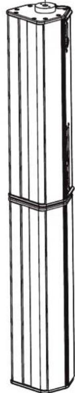
2.1 The E 435 Mid/High Unit
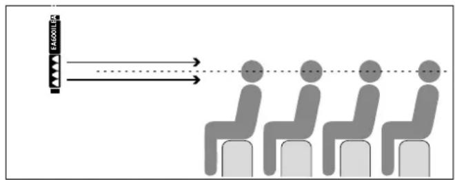
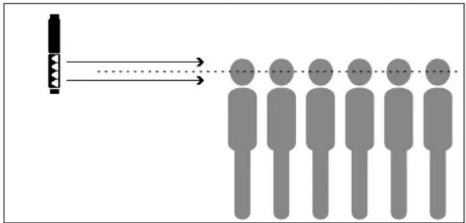
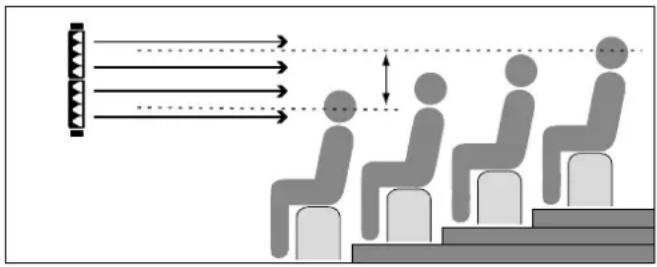
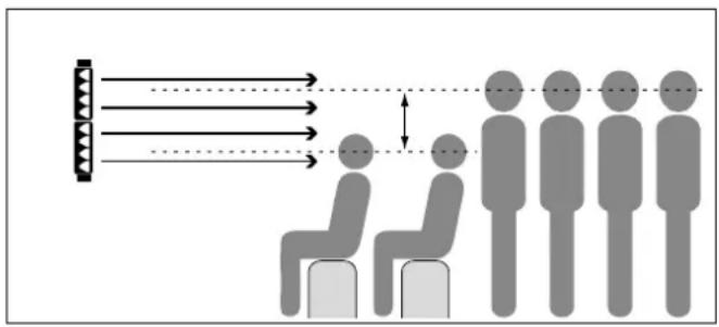
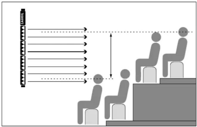
The E 435 mid/high unit is loaded with four 3.5^ high-performance speakers developed specifically for ELEMENTS. These four vertically arrayed speakers achieve a very even pattern of throw, with the volume, frequency spectrum, and audio image remaining uniform throughout the audience area. One column made up of passive units may comprise up to six E 435 mid/high units (and four E 435s with the Install Kit for active units), which are quickly and reliably connected via the E-Connect coupler.
2.2 The EA 600 IL Amp
Housed in an enclosure that shares the same design as the E 435 mid/ high unit, the EA 600 IL amp module delivers 600 watts at 4 ohms. You can use it to drive up to four E 435 mid/high units. The power amp module is ventilated from the front.
Connections and Control Features:
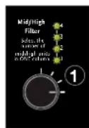
1 Mid/ High Filter with four LED indicators
Twist this rotary selector to select the correct EQ setting for one to four connected E 435 mid/high units. Set the switch to 2 when connecting two E 435 mid/high units; set it to 4 when connecting four mid/high units. The four LEDs indicate the selected EQ setting - one LED lights up to show the EQ setting for one mid/high unit; two LEDs light up for the EQ for two mid/high units, and so forth. The
unit of measure for this display is the smaller of the ELEMENTS mid/high units; that is, the E 435. The E 835 mid/high unit is twice as large and therefore counts as two E 435s.
2 Sensitivity Switch
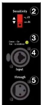
Use this selector to match the preamp's input gain to the mixer's output signal level. Engage it to select either -10 dBu, for example, for unbalanced 14 (6.3 mm) jacks and consumer level devices, or +4 dBu, which is standard for balanced XLR ports, professional mixers, and the like. Our recommendation: Select +4 dB when using a mixer equipped with balanced outputs. This lets you take advantage of console faders' full control range and helps prevent overloads. Opt for -10 dB when using a console with a lower output level (such as an unbalanced 14 (6.3 mm) output). Heads up: When using several amps in the same system, be sure to set all their Sensitivity switches to the same position; that is, +4 dBu or -10 dBu.
3 Status LED
This dual-color LED shows the signal's status: green = signal; red = limiter. The LED lights up red when amp's incoming signal level is too high or there is an error. If it lights up red briefly or intermittently, this simply indicates that the limiter is responding to signal peaks.
Caution! The system is being overloaded if the Status LED is constantly in the red. If the LED remains red but no audio signal is audible, there is an error.
4 Combination XLR/14" (6.3 mm) jack
This dual-purpose port accepts both XLR and 1/4 (6.3 mm) jack plugs. Use a mic cord equipped with XLR connectors to route the signal from your mixer (via master left/right, line out, or a similar circuit) to the balanced inputs. The XLR connectors' pin assignments must be as follows: 1 = ground, 2 = + , 3 = - . You may also use a 1/4 (6.3 mm) stereo jack plug to route signals via balanced circuits. Unbalanced signals can be patched in via a mono plug.
5 Through Port
This parallel output routes the line signal on to further EA600 IL amps or other components such as active monitors, monitor power amps, and the like via a cord equipped with XLR connectors.
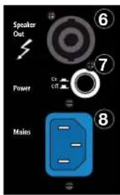
6 Speaker Out
This Speakon NL4 output is not used in conjunction with the Install Kit E 435 A.
7 Power Switch
When you switch the system's amp on, the Signal LED lights up red for about five seconds and then changes to green, indicating the amp is ready to operate.
8 Mains Input
Use the factory-included IEC cord to connect this socket to a wall outlet. Note: The EA 600 IL is equipped with a V-Lock mains cord retainer. If you use an optionally available Volex locking cord or another brand of cord with a compatible design, you can lock the mains cord in place to prevent accidental disconnection.
Caution! Make sure the local mains voltage matches the voltage specified on the EA 600 IL. Connecting it to the wrong mains voltage may destroy its electronic components.
2.3 E-Connect
The E-Connect audio bus/ mechanical coupler connects ELEMENTS components without any additional loudspeaker cords.
The mid/high unit's E-Connect shaft has a detent button that locks in place in the other unit's E-Connect sleeve. This coupler connects the two components mechanically and the integrated bus routes the audio signal through without requiring any outside cords. To separate the two components, press the detent button and disengage the two modules.
3 Mounting
You will need these tools to proceed:
- Phillips head screwdriver
13 mm SW open-end wrench - 5 mm hex key
| Mounting units using a) up to four 5 mm screws or b) one or two 8 mm screws | Screw the two mounting brackets (2) to the wall, spacing them vertically to match the number and size of the Elements module you want to mount (see page 3 for dimensions). | |
| Install Kit for passive units only: Attach the terminal block (9) with the included screw to the retaining plate (3), which will later be mounted on top. | ||
| Attach the retaining plates (3) to the cover and base of the Install Kit using the M8 bolts (8), washers (7) and spacer sleeves. | ||
| Install Kit for passive units only: Insert the 14" (6.3 mm) plug into the mid/high unit's E-Connect port. | ||
| Align the Install Kit horizontally to aim the speakers, and then tighten all screws. Install Kit for passive units only: Connect a speaker cord (not included) to the Install Kit by way of the terminal block. | ||
| Now bolt the Install Kit with the attached retaining plates (3) to the mounting yokes. | The four holes let you adjust the unit to determine the desired distance from the wall. | |
| Use the M3 screws (4) to attach the cover plates to the two retaining plates. | ||
4 Alignment
5 Configurations
| Configuration Overall height | |
| Install Kit E 435/E 435 A 8 48 mm | *) HEADS UP: If you use one E 835 instead of two E 435 units, the overall height will decrease 20 mm for each E 835 in the array (see page 3 for more on this) |
| Installkit + 1x E 435 1230 mm | |
| Installkit + 2x E 435 1612 mm* | |
| Installkit + 3x E 435 1994 mm* | |
| Installkit + 4x E 435** 2376 mm* |
6 Technical Data
| EA 600 IL Power Amp |
| Continuous power output, EIA: 600 watts Class D @ 4 ohms |
| Input sensitivity: +4 dBi/ -10 dBi (switchable) |
| Active protective circuit: RMS Limiter |
| Protection: DC, Load, Thermal |
| Filter: Subsonic filter, 4 system filters |
| Cooling: Temperature-controlled fan |
| Connections: Combination XLR/ 1/4" In, XLR Out, Speakon Parallel Out, E-Connect Out |
| Weight: 2.75 kg / 6.1 lbs |
| E 435 IL U/O Mid/High Unit |
| Nominal power handling: 150 W RMS |
| Frequency response -10 dB: 140 Hz - 20 kHz |
| Axial sensitivity 1W@1m: 97 dB half-space |
| Nominal Impedance: 16 ohms |
| Connections: 1 E-Connect in, 1 E-Connect out |
| Woofers: Four 3.5" wideband speakers |
| Directivity: 70° horizontal |
| X-over frequency: 140 Hz, 12 dB/ oct. passive |
| Weight: 2.35 kg / 5.2 lbs |
-性和 the hours per day.