PCE341 - Saw Porter-Cable - Free user manual and instructions
Find the device manual for free PCE341 Porter-Cable in PDF.

| Product type | Electric jigsaw |
| Brand | Porter-Cable |
| Model | PCE341 |
| Supply voltage | 120 V AC |
| Frequency | 60 Hz |
| Variable speed | Yes, with electronic speed control |
| Pendulum action | Yes, 3 positions (0, 1, 2) adjustable while in use |
| Blade change | Tool-less, with blade lock |
| Bevel angle | Adjustable from 0° to 45° left and right, with preset stops |
| Switch | With lock-on for continuous operation |
| Dust blower | Built-in |
| Anti-scratch sole plate | Removable to protect sensitive surfaces |
| Weight | Approximately 2 kg |
| Cord length | Approximately 2 m |
| Compatible materials | Wood, steel, aluminum, plastic, ceramic |
| Warranty | 3-year limited (material and manufacturing defects) |
| Recommended maintenance | Cleaning with compressed air, periodic lubrication of guide roller |
| Spare parts | Available via website or customer service |
| Optional accessories | Additional blades, parallel guide, compass bar |
Frequently Asked Questions - PCE341 Porter-Cable
User questions about PCE341 Porter-Cable
0 question about this device. Answer the ones you know or ask your own.
Ask a new question about this device
Download the instructions for your Saw in PDF format for free! Find your manual PCE341 - Porter-Cable and take your electronic device back in hand. On this page are published all the documents necessary for the use of your device. PCE341 by Porter-Cable.
USER MANUAL PCE341 Porter-Cable
natural_image
Technical line drawing of a mechanical device with mounting brackets and internal components (no text or symbols)PCE341
SAFETY GUIDELINES - DEFINITIONS
▲DANGER: indicates an imminently hazardous situation which, if not avoided, will result in death or serious injury.
⚠ WARNING: indicates a potentially hazardous situation which, if not avoided, could result in death or serious injury.
⚠️CAUTION: indicates a potentially haz ard ous situation which, if not avoided, may result in minor or moderate injury.
NOTICE: used without the safety alert symbol indicates potentially hazardous situation which, if not avoided, may result in property damage.

A WARNING:
risk of injury, read the instruction manual.
GENERAL POWER TOOL SAFETY WARNINGS
WARNING:
Read all safety warnings and all instructions Failure to follow the warnings and instructions may result in electric shock, fire and/or serious injury.
SAVE ALL WARNINGS AND INSTRUCTIONS FOR FUTURE REFERENCE
The term “power tool” in the warnings refers to your mains-operated (corded) power tool or battery-operated (cordless) power tool.
1) WORK AREA SAFETY
a) Keep work area clean and well lit. Cluttered or dark areas invite accidents.
b) Do not operate power tools in explosive atmospheres, such as in the presence of flammable liquids, gases or dust. Power tools create sparks which may ignite the dust or fumes.
c) Keep children and bystanders away while operating a power tool. Distractions can cause you to lose control.
2) ELECTRICAL SAFETY
a) Power tool plugs must match the outlet. Never modify the plug in any way. Do not use any adapter plugs with earthed (grounded) power tools. Unmodified plugs and matching outlets will reduce risk of electric shock.
b) Avoid body contact with earthed or grounded surfaces such as pipes, radiators, ranges and refrigerators. There is an increased risk of electric shock if your body is earthed or grounded.
c) Do not expose power tools to rain or wet conditions. Water entering a power tool will increase the risk of electric shock.
d) Do not abuse the cord. Never use the cord for carrying, pulling or unplugging the power tool. Keep cord away from heat, oil, sharp edges or moving parts. Damaged or entangled cords increase the risk of electric shock.
e) When operating a power tool outdoors, use an extension cord suitable for outdoor use. Use of a cord suitable for outdoor use reduces the risk of electric shock.
f) If operating a power tool in a damp location is unavoidable, use a ground fault circuit interrupter (GFCI) protected supply. Use of a GFCI reduces the risk of electric shock.
3) PERSONAL SAFETY
a) Stay alert, watch what you are doing and use common sense when operating a power tool. Do not use a power tool while you are tired or under the influence of drugs, alcohol or medication. A moment of inattention while operating power tools may result in serious personal injury.
b) Use personal protective equipment. Always wear eye protection. Protective equipment such as dust mask, non-skid safety shoes, hard hat, or hearing protection used for appropriate conditions will reduce personal injuries.
c) Prevent unintentional starting. Ensure the switch is in the off-position before connecting to power source and/or battery pack, picking up or carrying the tool. Carrying power tools with your finger on the switch or energizing power tools that have the switch on invites accidents.
d) Remove any adjusting key or wrench before turning the power tool on. A wrench or a key left attached to a rotating part of the power tool may result in personal injury.
e) Do not overreach. Keep proper footing and balance at all times. This enables better control of the power tool in unexpected situations.
f) Dress properly. Do not wear loose clothing or jewelry. Keep your hair, clothing and gloves away from moving parts. Loose clothes, jewelry or long hair can be caught in moving parts.
g) If devices are provided for the connection of dust extraction and collection facilities, ensure these are connected and properly used. Use of dust collection can reduce dust-related hazards.
4) POWER TOOL USE AND CARE
a) Do not force the power tool. Use the correct power tool for your application. The correct power tool will do the job better and safer at the rate for which it was designed.
b) Do not use the power tool if the switch does not turn it on and off. Any power tool that cannot be controlled with the switch is dangerous and must be repaired.
c) Disconnect the plug from the power source and/or the battery pack from the power tool before making any adjustments, changing accessories, or storing power tools. Such preventive safety measures reduce the risk of starting the power tool accidentally.
d) Store idle power tools out of the reach of children and do not allow persons unfamiliar with the power tool or these instructions to operate the power tool. Power tools are dangerous in the hands of untrained users.
e) Maintain power tools. Check for misalignment or binding of moving parts, breakage of parts and any other condition that may affect the power tool's operation. If damaged, have the power tool repaired before use. Many accidents are caused by poorly maintained power tools.
f) Keep cutting tools sharp and clean. Properly maintained cutting tools with sharp cutting edges are less likely to bind and are easier to control.
g) Use the power tool, accessories and tool bits etc., in accordance with these instructions taking into account the working conditions and the work to be performed. Use of the power tool for operations different from those intended could result in a hazardous situation.
5) SERVICE
a) Have your power tool serviced by a qualified repair person using only identical replacement parts. This will ensure that the safety of the power tool is maintained.
ADDITIONAL SPECIFIC SAFETY INSTRUCTIONS FOR JIG SAWS
- Hold power tool by insulated gripping surfaces, when performing an operation where the cutting accessory may contact hidden wiring or its own cord. Cutting accessory contacting a "live" wire may make exposed metal parts of the power tool "live" and could give the operator an electric shock.
- Use clamps or another practical way to secure and support the workpiece to a stable platform. Holding the work by hand or against your body leaves it unstable and may lead to loss of control.
- Allow the motor to come to a complete stop before withdrawing the blade from the kerf (the slot created by cutting). A moving blade may impact the workpiece causing a broken blade, workpiece damage or loss of control and possible personal injury.
- Keep handles dry, clean, free from oil and grease. This will enable better control of the tool.
- Keep blades sharp. Dull blades may cause the saw to swerve or stall under pressure.
- Clean out your tool often, especially after heavy use. Dust and grit containing metal particles often accumulate on interior surfaces and could create an electric shock hazard.
- Do not operate this tool for long periods of time. Vibration caused by the operating action of this tool may cause permanent injury to fingers, hands, and arms. Use gloves to provide extra cushion, take frequent rest periods, and limit daily time of use.
- Air vents often cover moving parts and should be avoided. Loose clothes, jewelry or long hair can be caught in moving parts.
- An extension cord must have adequate wire size (AWG or American Wire Gauge) for safety. The smaller the gauge number of the wire, the greater the capacity of the cable, that is 16 gauge has more capacity than 18 gauge. An undersized cord will cause a drop in line voltage resulting in loss of power and overheating. When using more than one extension to make up the total length, be sure each individual extension contains at least the minimum wire size. The following table shows the correct size to use depending on cord length and nameplate ampere rating. If in doubt, use the next heavier gauge. The smaller the gauge number, the heavier the cord.
| Minimum Gauge for Cord Sets | ||||||
| Ampere Rating | Volts Total Length of Cord in Feet (meters) | |||||
| 120V 25 (7.6) 50 (15.2) 100 (30.5) 150 (45.7) | ||||||
| 240V 50 (15.2) 100 (30.5) 200 (61.0) 300 (91.4) | ||||||
| More Than | Not More Than | AWG | ||||
| 0 6 18 | 16 16 14 | |||||
| 6 | 10 | 18 | 16 | 14 | 12 | |
| 10 | 12 | 16 16 14 12 | ||||
| 12 | 16 | 14 12 | Not Recommended | |||
⚠ WARNING: ALWAYS use safety glasses. Everyday eyeglasses are NOT safety glasses. Also use face or dust mask if cutting operation is dusty. ALWAYS WEAR CERTIFIED SAFETY EQUIPMENT:
• ANSI Z87.1 eye protection (CAN/CSA Z94.3),
• ANSI S12.6 (S3.19) hearing protection,
• NIOSH/OSHA/MSHA respiratory protection.
WARNING:
Some dust created by power sanding, sawing, grinding, drilling,
and other construction activities contains chemicals known to the State of California to cause cancer, birth defects or other reproductive harm. Some examples of these chemicals are:
- lead from lead-based paints,
• crystalline silica from bricks and cement and other masonry products, and
• arsenic and chromium from chemically-treated lumber.
Your risk from these exposures varies, depending on how often you do this type of work. To reduce your exposure to these chemicals: work in a well ventilated area, and work with approved safety equipment, such as those dust masks that are specially designed to filter out microscopic particles.
- Avoid prolonged contact with dust from power sanding, sawing, grinding, drilling, and other construction activities. Wear protective clothing and wash exposed areas with soap and water. Allowing dust to get into your mouth, eyes, or lay on the skin may promote absorption of harmful chemicals.
WARNING:
Use of this tool can generate and/or disburse dust, which may
cause serious and permanent respiratory or other injury. Always use NIOSH/OSHA approved respiratory protection appropriate for the dust exposure. Direct particles away from face and body.
WARNING:
Always wear proper personal hearing protection that conforms
to ANSI S12.6 (S3.19) during use. Under some conditions and duration of use, noise from this product may contribute to hearing loss.
- The label on your tool may include the following symbols. The symbols and their definitions are as follows:
V.....volts A.....amperes
Hz......hertzW......watts
min......minutes \~ ......alternating current
---.....direct current .....alternating or direct
Class I Construction current
(grounded)
n_0 ..... no load speed
☐...... Class II Construction) ⊕...... earthing terminal
(double insulated) A...... safety alert symbol
SAVE THESE INSTRUCTIONS
MOTOR
Be sure your power supply agrees with nameplate marking. 120 Volts AC means your tool will operate on alternating current. As little as 10% lower voltage can cause loss of power and can result in overheating. All PORTER-CABLE tools are factory-tested; if this tool does not operate, check the power supply.
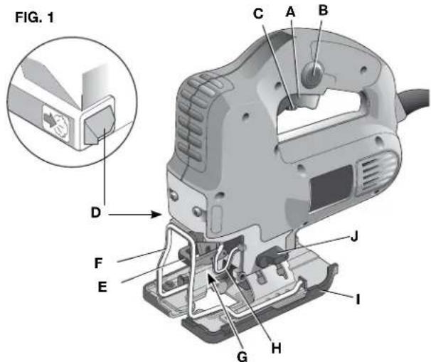
COMPONENTS (FIG. 1)
⚠ WARNING: Never modify the power tool or any part of it. Damage or personal injury could result.
Your PCE341 jigsaw has been designed for professional cutting of wood, steel, aluminium, plastic and ceramic material.
A. On/off switch G. Blade holder
B. Lock-on button H. Guide roller
C. Speed control dial I. Shoe
D. Sawdust blower J. Pendulum stroke selector
E. Blade latch
F. Finger guard
text_image
FIG. 1 C A B D F J E I G HASSEMBLY AND ADJUSTMENT
⚠ WARNING: To reduce the risk of injury, turn unit off and disconnect it from power source before installing and removing accessories, before adjusting or when making repairs. An accidental start-up can cause injury.
CHECKING AND CHANGING THE SAW BLADE
- Only use saw blades conforming to the specifications contained in these operating instructions.
- Only sharp saw blades in perfect working condition should be used; cracked or bent saw blades should be discarded and replaced at once.
• Ensure that the saw blade is securely fixed. - The saw blade may be hot due to usage. When changing the blade make sure the blade is cool or wear protective gloves when touching the blade.
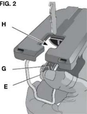
FITTING AND REMOVING A SAW BLADE (FIG. 2)
⚠ WARNING: The saw blade may be hot due to usage. When changing the blade make sure the blade is cool or wear protective gloves when touching the blade.
The tool-free blade exchange system ensures quick and easy changing of saw blades.
- Open the blade holder (G) by fully retracting the blade latch (E).
- Insert the saw blade into the blade holder (G) guiding the back of the blade into the groove of the guide roller (H).
- Release the blade latch (E).
To remove the saw blade, fully retract the blade latch and pull the blade out of the holder.
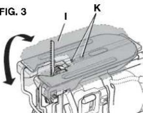
SETTING THE BEVEL ANGLE (FIG. 3)
The adjustable shoe (l) allows cutting of LH and RH bevel angles up to 45°. The bevel scale has preset positions at 0° and 45°.
- Loosen the screws (K) using the supplied wrench.
- Slide the shoe (l) toward the saw blade.
- Tilt the shoe and set the desired bevel angle using the scale.
- Tighten the screws.
FIG. 2
text_image
FIG. 2 H G EFIG. 3
text_image
FIG. 3 I KSETTING THE PENDULUM STROKE (FIG. 1)
The adjustable pendulum stroke guarantees a perfect cutting stroke for different materials.
Slide the selector (J) to the desired position referring to the table below. The selector can be manipulated during operation.
| 2 Fast cuts – PVC | ||
| 2 Thick workpieces – Fibreglass | Acrylic | |
| 1 Plywood Aluminium - Chipboard Non-ferrous | ||
| 0 Thin workpieces Fine cuts | Sheet metal | - |
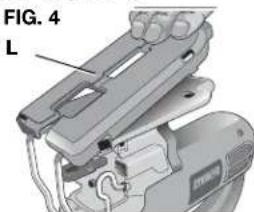
MOUNTING THE PLASTIC ANTI-SCRATCH SHOE COVER (FIG. 4)
The anti-scratch shoe cover (L) reduces damage to the surface of (sensitive) workpieces.
Click the cover onto the shoe as shown.
text_image
FIG. 4 LINSTRUCTIONS FOR USE
⚠ WARNING: To reduce the risk of injury, turn unit off and disconnect it from power source before installing and removing accessories, before adjusting or when making repairs. An accidental start-up can cause injury.
WARNING:
• Always observe the safety instructions and applicable regulations.
- Make sure your workpiece is well secured. Remove nails, screws and other fasteners that may damage the blade.
- Check that there is sufficient space for the blade underneath the workpiece. Do not cut materials that exceed the maximum cutting depth of the blade.
- Use sharp saw blades only. Damaged or bent saw blades must be removed immediately.
- Do not use the tool for sawing pipes or tubes.
- Never run your tool without a saw blade.
- For optimal results, move the tool smoothly and constantly over the workpiece. Do not exert lateral pressure on the saw blade. Keep the shoe flat on the workpiece and lead the cord away in line with the tool. When sawing curves, circles or other round shapes, push the tool gently forward.
- Wait until the tool has come to a standstill before removing the saw blade from the workpiece. After sawing the blade may be very hot. Do not touch.
TURNING ON AND OFF (FIG. 1)
To run the tool, press the on/off switch (A).
To stop the tool, release the switch.
For continuous operation, press and hold down the switch (A), press the lock-on button (B) and release the switch.
To stop the tool in continuous operation, press the switch briefly and release it. Always switch off the tool when work is finished and before unplugging.
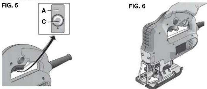
SETTING THE ELECTRONIC SAWING SPEED (FIG. 5)
⚠ WARNING: After using the tool for an extended period on low speed settings, run it for approx. 3 minutes on maximum no-load speed.
The sawing speed varies with the pressure exerted on the on/off switch (A).
To preset the sawing speed, turn the control dial (C) to the desired level. The higher the rate, the higher the sawing speed. The required setting depends on the thickness and kind of material.
Use high speeds for sawing soft materials such as wood. Use low speeds for sawing metal.
HOLDING THE TOOL (FIG. 6)
Hold the tool as shown.
8 - ENG
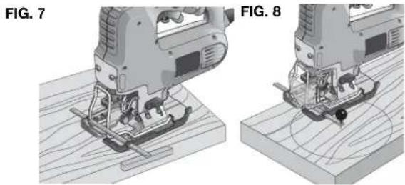
SAWING IN WOOD (FIG. 7)
- If necessary, draw a cutting line.
- Switch the tool on.
- Hold the tool against the workpiece and follow the line.
For sawing parallel to the edge of your workpiece, install the parallel fence and guide your jigsaw along the workpiece a shown in Figure 7.
SAWING IN WOOD USING A PILOT HOLE (FIG. 8)
- If necessary, draw a cutting line.
- Drill a hole (ø 12 mm minimum) and introduce the saw blade.
- Switch the tool on.
- Follow the line.
For cutting perfectly round shapes, install the trammel bar and set it to the required radius.
natural_image
Technical illustration of two views (FIG. 7 and FIG. 8) showing a hand operating a wooden tool with no visible text or symbols.SAWING IN METAL
⚠ WARNING: Use a cooling lubricant (cutting oil) to prevent overheating of the saw blade or the workpiece.
- Mount an appropriate saw blade.
- Proceed as described above.
TROUBLESHOOTING
For assistance with your tool, visit our website at www.portercable.com for a list of service centers, or call the PORTER-CABLE Customer Care Center at (888) 848-5175
MAINTENANCE
⚠ WARNING: To reduce the risk of injury, turn unit off and disconnect it from power source before installing and removing accessories, before adjusting or when making repairs. An accidental start-up can cause injury.
CLEANING
⚠ WARNING: Blow dirt and dust out of all air vents with dry air at least once a week. Wear proper ANSI Z87.1 (CAN/CSA Z94.3) eye protection and proper NIOSH/OSHA/MSHA respiratory protection when performing this.
⚠ WARNING: Never use solvents or other harsh chemicals for cleaning the non-metallic parts of the tool. These chemicals may weaken the materials used in these parts. Use a cloth dampened only with water and mild soap. Never let any liquid get inside the tool; never immerse any part of the tool into a liquid.
FAILURE TO START
Should your tool fail to start, check to make sure the prongs on the cord plug are making good contact in the outlet. Also, check for blown fuses or open circuit breakers in the line.
LUBRICATION
LUBRICATING THE GUIDE ROLLER (FIG. 2)
Apply a drop of oil to the guide roller (H) at regular intervals to prevent jamming.
SERVICE
REPLACEMENT PARTS
Use only identical replacement parts. For a parts list or to order parts, visit our service website at www.portercable.com. You can also order parts from your nearest PORTER-CABLE Factory Service Center or PORTER-CABLE Authorized Warranty Service Center. Or, you can call our Customer Care Center at (888) 848-5175.
SERVICE AND REPAIRS
All quality tools will eventually require servicing and/or replacement of parts. For information about PORTER-CABLE, its factory service centers or authorized warranty service centers, visit our website at www.portercable.com or call our Customer Care Center at (888) 848-5175. All repairs made by our service centers are fully guaranteed against defective material and workmanship. We cannot guarantee repairs made or attempted by others.
You can also write to us for information at PORTER-CABLE, 4825 Highway 45 North, Jackson, Tennessee 38305 - Attention: Product Service. Be sure to include all of the information shown on the nameplate of your tool (model number, type, serial number, etc.).
ACCESSORIES
WARNING:
Since accessories, other than those offered by PORTER-CABLE,
have not been tested with this product, use of such accessories with this tool could be hazardous. To reduce the risk of injury, only PORTER-CABLE recommended accessories should be used with this product.
A complete line of accessories is available from your PORTER-CABLE Factory Service Center or a PORTER-CABLE Authorized Warranty Service Center. Please visit our Web Site www.portercable.com for a catalog or for the name of your nearest supplier.
OPTIONAL ACCESSORIES
Consult your dealer for a complete list of appropriate accessories.
These include:
PC1203-3
Blade
PC1200H-3
Blade
PC1215H-3
Blade
PC1212H-3
Blade
PC1224M-3
Blade
THREE YEAR LIMITED WARRANTY
PORTER-CABLE will repair, without charge, any defects due to faulty materials or workmanship for three years from the date of purchase. This warranty does not cover part failure due to normal wear or tool abuse. For further detail of warranty coverage and warranty repair information, visit www.portercable.com or call (888) 848-5175. This warranty does not apply to accessories or damage caused where repairs have been made or attempted by others. This warranty gives you specific legal rights and you may have other rights which vary in certain states or provinces.
In addition to the warranty, PORTER-CABLE tools are covered by our:
1 YEAR FREE SERVICE: PORTER-CABLE will maintain the tool and replace worn parts caused by normal use, for free, any time during the first year after purchase.
90 DAY MONEY BACK GUARANTEE: If you are not completely satisfied with the performance of your PORTER-CABLE Power Tool, Laser, or Nailer for any reason, you can return it within 90 days from the date of purchase with a receipt for a full refund – no questions asked.
LATIN AMERICA: This warranty does not apply to products sold in Latin America. For products sold in Latin America, see country specific warranty information contained in the packaging, call the local company or see website for warranty information.
To register your tool for warranty service visit our website at www.portercable.com.
WARNING LABEL REPLACEMENT
If your warning labels become illegible or are missing, call (888) 848-5175 for a free replacement.
Model PCE341 VS Jigsaw
SER.
WARNING
TO REDUCE THE RISK OF INJURY, USER MUST READ INSTRUCTION MANUAL.
ALWAYS USE PROPER EYE AND RESPIRATORY PROTECTION. ADVERTENCIA: PARA DISMINUIR EL RIESGO DE LESIONES, EL USUARIO DEBERÁ LEER EL MANUAL DE INSTRUCCIONES. SIEMPRE SE DEBERÁ LLEVAR LA PROTECCIÓN APROPIADA PARA LA VISTA Y PARA LAS VIAS RESPIRATORIAS. AVERTISSEMENT; A TITRE PRÉVENTIF, LIRE LE GUIDE. IL FAUT TOUJOURS PORTER DE L'ÉQUIPEMENT DE PROTECTION OCULAIRE ET RESPIRATIORE APPROPRIE. PORTER-CABLE, JACKSON, TENNESSEE 38305 U.S.A.
MESURES DE SÉCURITÉ - DÉFINITIONS
text_image
FIG. 1 C A B D F J E I G Htext_image
FIG. 3 I KRÉGLAGE DU MOUVEMENT PENDULAIRE (Fig. 1)
text_image
FIG. 5 A C
natural_image
Illustration of a hand operating a small electronic device labeled FIG. 6 (no text or symbols on the device itself)COUPE DU BOIS (Fig. 7)
natural_image
Two technical diagrams showing a hand operating a wooden surface with a moving tool, labeled FIG. 7 and FIG. 8 (no text or symbols on the diagram itself)COUPE DU MÉTAL
PORTER-CABLE, JACKSON, TENNESSEE 38305 U.S.A.
--- ...corriente directa ....corriente alterna o directa
text_image
FIG. 1 C A B D F J E I G H27 - SP
MONTAJE Y AJUSTES
ADVERTENCIA:
text_image
FIG. 2 H G EAJUSTE DEL ÁNGULO DE BISEL (FIG. 3)
text_image
FIG. 3 I KAJUSTE DE LA CARRERA DEL PÉNDULO (FIG. 1)
natural_image
Mechanical assembly diagram showing a clamping device with labeled component (FIG. 4), no readable text or symbols present.text_image
FIG. 5 A C
natural_image
Illustration of a hand operating a manual fDelta tool (no text or symbols visible)CORTE DE MADERA (FIG. 7)
natural_image
Two 3D diagrams showing a hand operating a wooden surface with a cutaway view of the mechanism (no text or symbols present)CORTE DE METAL
Local D, Col. Obrera (55) 5588 9377
MERIDA, YUC
Calle 63 #459-A - Col. Centro (999) 928 5038
MONTERREY, N.L.
Av. Francisco I. Madero 831 Poniente - Col. Centro (818) 375 23 13
PUEBLA, PUE
17 Norte #205 - Col. Centro (222) 246 3714
QUERETARO, QRO
Av. San Roque 274 - Col. San Gregorio (442) 2 17 63 14
SAN LUIS POTOSI, SLP
The following are PORTER-CABLE trademarks for one or more power tools and accessories: a gray and black color scheme; a ♦ “four point star” design; and three contrasting/outlined longitudinal stripes.
Trademarks noted with ® are registered in the United States Patent and Trademark Office and may also be registered in other countries. Other trademarks may apply.
4825 Highway 45 North
Jackson, TN 38305
(888) 848-5175
www.portercable.com