CHLA250EVC - Garage door CHAMBERLAIN - Free user manual and instructions
Find the device manual for free CHLA250EVC CHAMBERLAIN in PDF.
| Product type | Swing gate opener for garage doors |
| Brand | Chamberlain |
| Model | CHLA250EVC |
| Dimensions (piston stroke) | 300 mm |
| Kit weight | 19.6 kg |
| Power supply | 220-240 VAC, 50/60 Hz |
| Motor voltage | 24 VDC |
| Rated motor power | 100 W (2 x 50 W) |
| Maximum push/pull force | 1250 N |
| Maximum opening angle | 110° |
| Maximum weight per leaf | 200 kg (for 1.5 m width) |
| Main functions | 24 VDC motorization, integrated remote controls, photocells, optional backup battery, programming via control panel, close timer, myQ compatible |
| Maintenance | Check monthly the fastenings and the proper functioning of the gate |
| Safety | Infrared photocells, 8.2 kΩ safety edge, automatic reversal in case of obstacle, emergency manual release |
| Spare parts and repairability | Backup battery SKU 490EV, remote controls TX4REV-F, photocells, electronic/magnetic lock |
| General information | Warranty at www.chamberlain.eu, CE compliance per directives 2006/42/EC and 2014/53/EU |
Frequently Asked Questions - CHLA250EVC CHAMBERLAIN
User questions about CHLA250EVC CHAMBERLAIN
0 question about this device. Answer the ones you know or ask your own.
Ask a new question about this device
Download the instructions for your Garage door in PDF format for free! Find your manual CHLA250EVC - CHAMBERLAIN and take your electronic device back in hand. On this page are published all the documents necessary for the use of your device. CHLA250EVC by CHAMBERLAIN.
USER MANUAL CHLA250EVC CHAMBERLAIN
natural_image
Line drawing of a mechanical tool or device with no visible text, numbers, or symbolsen Swing Gate Operator Installation Manual*
* For GB (UK, NI) specific information on national regulations and requirements see English part of the manual.
NOTE: The original installation and operating instructions were compiled in English. Any other available language is a translation of the original English version.
- SAFETY INSTRUCTIONS AND INTENDED USE....2
- DELIVERY SCOPE....4
- TOOLS NEEDED......4
- OVERVIEW OF GATE OPERATOR....4
- MECHANICAL INSTALLATION....5
5.1 Dimensions of Gate and Operator....5
5.2 Post Bracket Position and A&B Dimensions....5
5.3 Post Bracket Installation....6
5.4 Operator Mounting and Travel Distance Adjustment....6
5.5 Hardstop Installation....7
5.6 Emergency Release Mechanism....8
5.7 Control Box Installation....8
5.8 Power Wiring....8
-
WIRING DIAGRAM....9
-
PROGRAMMING....10
7.1 Display, Programming Buttons and Function Setting....10
7.2 General Programming Overview....10
7.3 Wing Movement Direction....11
7.4 Basic Settings....11
7.4.1 Application Settings....11
7.4.2 Direction Motor 1 Settings....11
7.4.3 Direction Motor 2 Settings....11
7.4.4 Limit Learning....11
7.5 Stand-by Mode....12
7.6 Programming and Erasing of Remote Controls, Radio Accessories and myQ Devices....13
7.7 Advanced Settings....14
7.7.1 Overview Advanced Settings....14
7.7.2 Transmitter Settings....14
7.7.3 Infrared Photocells Settings....14
7.7.4 Input Settings....14
7.7.5 Partial Opening Motor 1....15
7.7.6 Delay Motor 2 in Open Direction....15
7.7.7 Delay Motor 1 in Close Direction....15
7.7.8 Timer to Close....15
7.7.9 Reversal Time after Impact....15
7.7.10 E-Lock / Mag-Lock Settings....15
7.7.10a Relief Motor 1 for E-Lock....16
7.7.11 Flashing Light Settings....16
7.7.11a Pre-Flashing....16
7.7.12 Special Contact Settings....16
7.7.13 Start Speed in Open and Close Directions....16
7.7.14 Maintenance Counter....16
7.8 Factory Default Settings....16
7.9 Finish and Exit....16
BATTERY BACKUP....16
ERROR CODES....17
TECHNICAL DATA....18
MAINTENANCE....19
DISPOSAL....19
WARRANTY....19
DECLARATION OF CONFORMITY....19
1. SAFETY INSTRUCTIONS AND INTENDED USE
About this Manual – Original Manual
These instructions are the original operating instructions according to the machinery directive 2006/42 EC. The instruction manual must be read carefully to understand important product information. Pay attention to the safety and warning notices. Keep the manual in safe place for future reference and to make it available to all persons for inspection, service, maintenance and repair. After installation pass the complete documentation to the responsible person/owner.
Qualification of a competent installer
Only correct installation and maintenance by a competent installer (specialist) / competent company, in accordance with the instructions, must understand and ensure the safe and intended function of the installation. Specialist is, who on the basis of their technical training and experience, has sufficient knowledge in the field of powered gates and moreover is familiar with relevant state occupational safety regulations and generally accepted rules of technology in such an extent that he is also able to assess the safe working condition of powered gates according to EN 13241, 12604, 12453 (EN12635)
The installer must understand the following:
Before installing the drive, check that the driven part is in good mechanical condition, opens and closes properly and correctly balanced where applicable. Before first use and at least annually a specialist must inspect powered gate regarding their safe condition. After installation, the installer must ensure that the mechanism is properly adjusted and that the protection system and any manual release function correctly (EU: EN 13241, EN12604, EN 12453, EN 12635; GB (UK, NI) BS EN 13241, BS EN12604, BS EN 12453, BS EN12635). A regular maintenance, inspection must be carried out according to the standards. The installer must instruct other users on the safe operation of the drive system.
After successful installation of the drive system, the responsible installer, in accordance with the EU: Machinery Directive 2006/42/EC; GB (UK, NI): Supply of Machinery (Safety) Regulations 2008 SI 2008 No. 1597, must issue the EU: CE / GB (UK,NI): UK declaration of conformity for the gate system. The EU: CE / GB (UK,NI): UKCA mark label must be attached to the gate system. This is also obligatory in the process of retrofitting on a manually operated gate. Further, a handover pack and an inspection book must be completed.
After successful installation of the drive system, the responsible installer, in accordance with the EU: Machinery Directive 2006/42/EC; GB (UK, NI): Supply of Machinery (Safety) Regulations 2008 SI 2008 No. 1597, must issue the EU: CE / GB (UK,NI): UK declaration of conformity for the gate system. The EU: CE / GB (UK,NI): UKCA mark label must be attached to the gate system. This is also obligatory in the process of retrofitting on a manually operated gate. Further, a handover pack and an inspection book must be completed.
Please read the operating instructions and especially the precautions. The following symbols are placed in front of instructions to avoid personal injury or damage to property. Read these instructions carefully.
Warnings Symbols
The general warning symbol indicates a danger that can lead to injuries or death. In the text section, the general warning symbols are used as described below.
| DANGER Symbol WARNING Symbol | CAUTION Symbol ATTENTION Symbol | ||
 DANGER DANGER |  WARNING WARNING |  CAUTION CAUTION |  |
| Indicates a danger that leads directly to death or serious injuries. | Indicates a danger that can lead to death or serious injuries. | Indicates a danger that can lead to damage or destruction of the product. | Indicates a danger that can lead to damage or destruction of the product. |
Intended use
The swing gate operator is exclusively designed and tested for the operation of smooth-running swing gates in the residential, non-commercial sector.
Specification for gates are defined under mechanical requirements according EU: EN12604 / GB (UK, NI): BS EN 12604.
The maximum permissible gate size and the maximum weight must not be exceeded. The gate must open and close smoothly by hand. Use the operator on gates which comply with the applicable standards and guidelines. Regional conditions of wind loads must be taken into account when using door or gate panels EU: EN13241 / GB (UK, NI): BS EN 13241. Observe the manufacturer's specifications regarding the combination of door and operator. Possible hazards within the meaning of EU: EN13241 / GB (UK, NI): BS EN 13241 are to be avoided by designing and installing the door/gate according to the relevant instructions. This gate mechanism must be installed and operated in accordance with the appropriate safety rules.
Improper use
It is not intended for continuous operation and use in a commercial application.
The construction of the drive system is not designed for the operation of gates outside of manufacturers specification.
It is not permitted on gates that travel with incline/decline.
Any improper use of the drive system could increase the risk of accidents. The manufacturer assumes no liability for such usage. With this drive, automated gates must comply with the current, valid international and country-specific/local standards, guidelines and regulations (EU: EN 13241, EN12604, EN 12453; GB (UK, NI) BS EN 13241, BS EN12604, BS EN 12453).
Only Chamberlain and approved accessories may be connected to the drive. Incorrect installation and/or failure to comply with the following instructions may result in serious personal injury or damage to property.
Gate systems located in public areas and have only force limitation, can only be operated under full supervision.
Additional safety devises should be considered in accordance with EU: EN 12453; GB (UK, NI) BS EN 12453.
1. SAFETY INSTRUCTIONS AND INTENDED USE
During operation, the gate should not under any circumstances obstruct public path ways and roads (public area).
When using tools and small parts to install or carry out repair work on a gate exercise caution and do not wear rings, watches or loose clothing.
To avoid serious personal injury due to entrapments, remove any locking device fitted to the gate in order to prevent damage to the gate.
Installation and wiring must be in compliance with your local building and electrical installation regulations. Power cables must only be connected to a properly earthed supply.
Disconnect electric power to the system before installation, maintenance, repairs or removing covers. A disconnecting device must be provided to the mains power supply (permanently-wired installation) to guarantee all-pole disconnection (isolating switch or by a separate fuse). The repairs and electrical installations may be performed only by an authorised electrician. Emergency Stop Button must be installed for emergency case based on the risk assessment.
Ensure that entrapment between the driven part and the surrounding fixed parts due to the opening movement of the driven part is avoided by respecting the given safety distances in accordance with the EU: EN 13241, EN12604, EN 12453, EN 12635; GB (UK, NI) BS EN 13241, BS EN12604, BS EN 12453, BS EN12635 and/or with safety devices (e.g. safety edge).
Testing of the safety function of the drive system is recommended to be carried out at least once a month. Refer also to manufacturers instruction of the gate system components.
After the installation a final test of the full function of the system and the of the safety devices must be made and all users must be instructed in the function and operation of the swing gate operator.
Gate systems must meet the force limitation according EU: EN 12453, EN 60335-2-103; GB (UK, NI) BS EN 12453, BS EN 60335-2-103.
Additional safety device (safety edge,) must be considered in accordance to the standard by changes to the system.
It is important to make sure that the gate always runs smoothly. Gates which stick or jam must be repaired immediately. Employ a qualified technician to repair the gate, never attempt to repair it yourself. This device is not intended for use by persons (including children) with restricted physical, sensory or mental abilities or lack of experience or knowledge, unless they are supervised by a person responsible for their safety or have received instruction in how to use the device. If necessary, control equipment MUST be mounted within sight of the gate and out of reach of children. Children should be supervised to ensure that they do not play with the device. Do not allow children to operate push button(s) or remote(s). Misuse of the gate operator system can result in serious injury.
The warning signs should be placed in clearly visible locations.
The gate opener should ONLY be used if the user can see the entire gate area and is assured that it is free of obstacles and the gate operator is set correctly. No one may pass through the gate area while it is moving. Children must not be allowed to play in the vicinity of the gate.
The full protection against potential crushing or entrapment must work immediately when the drive arms are installed.
There may be existing hazards on mechanical, electrical installation or the closing edges of the gate by crushing, impact points:
- Structural failure, leaf, hinges, fixings, travel stops, wind load
- Crush, hinge area, under the gate, safety distance on fixed object
- Electrical failure (Control – faults in safety systems)
- Impact, swept area, hold to run, force limitation, presence detection
Appropriate measures must be taken to ensure safe operation of the gate system according the standards.
Never start up a damaged drive.
Use the manual release only to disengage the drive and – if possible – ONLY when is gate closed. Operation of the emergency manual release can lead to uncontrolled movements of the gate. The Timer-to-Close (TTC) feature, the myQ Smartphone Control app, are examples of unattended operation of the gate.
Any device or feature that allows the gate to close without being in the line of sight of the gate is considered as unattended open/close.
The Timer-to-Close (TTC) feature, the myQ Smartphone Control, and any other myQ devices can ONLY be activated when Chamberlains photo cells are installed (TTC works only in close direction). The gate shall only be operated in the direct sight line to the gate.
IMPORTANT INFORMATION!
• This procedure is also required on private installations (new or retrofitted to a manually operated gate).
This installation and operating manual must be retained by the user.
• The manufacturer accepts no liability/warranty claims resulting from use other than intended use and after the warranty expires.
- The legal remedy is the sole responsibility for all associated rights.
NOTE: Observe the installation and operating manual.
• Always monitor the function of the system and rectify the cause immediately in the event of a malfunction.
- Carry out an annual inspection of the system. Call a specialist.
- Safety distances must be respected between the gate leaf and the environment in accordance with related standards.
• The operator can be installed Only on stable and rigid gate leaves. Gate leaves must not bend or twist when opening and closing.
- Assure that the hinges of the gate leaf are installed and working correctly and not creating any obstacles.
• Installation of two operators on same door leaf is strictly prohibited.
- Observe the corresponding requirements of the local, national regulations for compliance with the measures to protect human health, which must be observed when contacting other people, including employees, suppliers and customers (e.g. safety distance, mask requirement, etc).
- Precise information can be requested from the local authorities.

2. DELIVERY SCOPE
CHLA250EVC (2 x motor units)
natural_image
Line drawing of a welding torch (no text or symbols)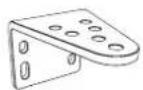
Post Mounting Bracket (2x)
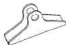
Gate Mounting Bracket (2x)

Pin (4x) Clevis Pin (4x)

Control Box Remote

Control (2x)


Photocell Release Key (4x)

Installation Manual
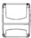
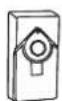
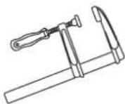
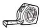
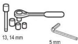
3. TOOLS NEEDED
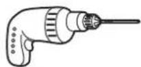

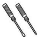
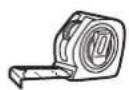
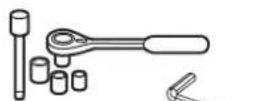
13, 14 mm
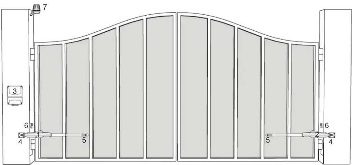
4. OVERVIEW OF GATE OPERATOR

- Motor 1
- Motor 2
- Control board
- Post bracket
- Gate bracket
- Infrared photocells
- Flashing lamp
5. MECHANICAL INSTALLATION
Herewith you start mechanical installation of the gate operator.
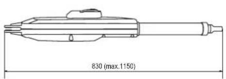
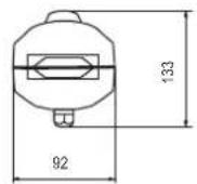
5.1 Dimensions of Gate and Operator
CHLA250EVC
| CHLA250EVC | |
| 1.5 m 200 kg | |
| 2.0 m 150 kg | |
| 2.5 m 100 kg |
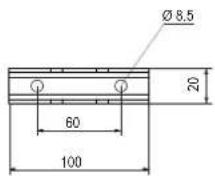
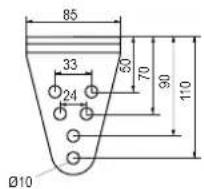
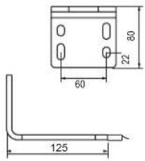
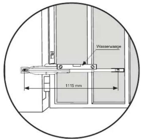
5.2 Post Bracket Position and A&B Dimensions
Determine the A and B dimension based on the opening angle provided in Table 1 to confirm the position where the post bracket will be mounted.
- To ensure that the motor does not touch the pillar, please define your C dimension using B-60 mm formula.
- For optimal mechanical advantage A and B dimension shall be equal or not differ by more than 40 mm.
NOTE: Smaller A and B dimensions determine higher peripheral speed of the leaf. Higher differences between A and B dimensions cause greater speed and force variations during the gate opening and closing movement. It is always good practice to use all available travel of the operator.
All crushing points must be secured by an entrapment protection according to EU: EN 12453, EN 60335-2-103; GB (UK, NI): BS EN 12453, BS EN 60335-2-103.
Example installation
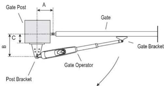
Gate leaf bracket extension shall be co- sidered in case the pivoting point of the gate is not centered with the gate leaf.
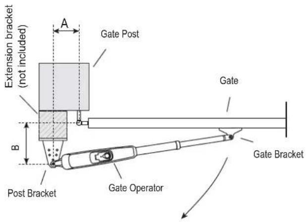
Table 1:
CHLA250EVC with external hardstop, using max 300 mm travel
| mm | A | |||||
| 100 120 140 160 180 | ||||||
| B | 100 n.a. 110^ 105^ 105^ 100^ | |||||
| 120 110° 110^ 100^ 95^ 95^ | ||||||
| 140 100° 100^ 100^ 90^ 80^ | ||||||
| 160 95^ 95^ 90^ 85^ 75^ | ||||||
| 180 90^ 90^ 80^ 75^ 70^ | ||||||
5. MECHANICAL INSTALLATION
5.3 Post Bracket Installation
CHLA250EVC
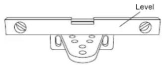
- Using the post bracket as a reference, mark and drill the holes for the post bracket.
- Attach the post bracket using the correct fastening material based on existing installation (building / material substance). Please consult the gate manufacturer.
- The slots on the post bracket allow for alignment. When the post bracket is level tighten the nuts.
NOTE: For brick or concrete posts please use correct dowels and screws. Please maintain correct distance to the post edges. For metal posts please consider the post thickness and weld or bolt the bracket directly to post. For timber posts please use correct screws and if required use reinforcement plates.
Caution: The fastened brackets must not loosen after installation and during operation.
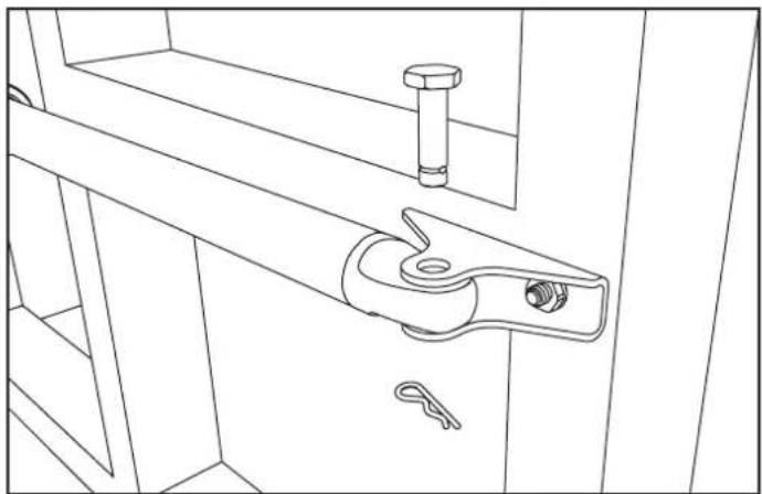
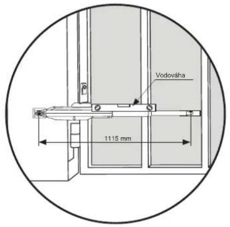
5.4 Operator Mounting and Travel Distance Adjustment
- Align the holes on the operator to the post bracket holes and connect using the circlip pin and circlip.
- Release the operator clutch with the release key (see page 8).
- Bring gate leaf to the CLOSED position.
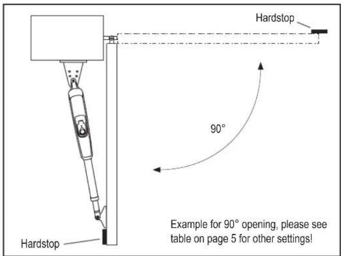
NOTE: The system must operate with:
CHLA250EVC only with external gate hard stops in both directions.
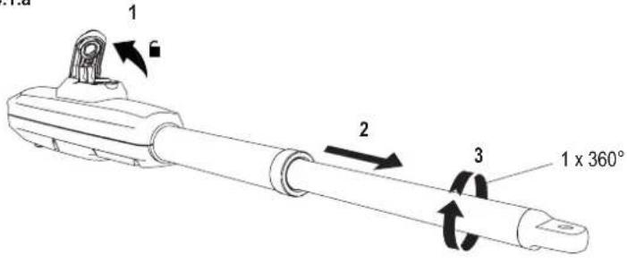
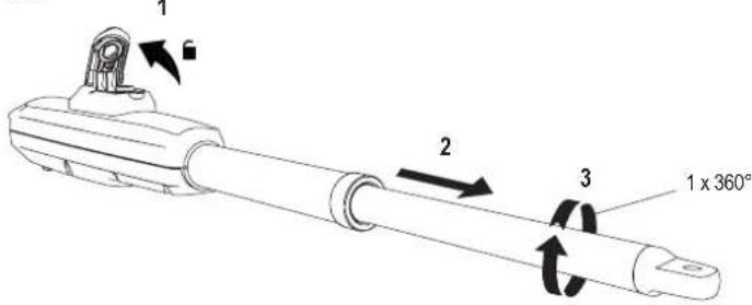
4.1 Installation with external gate hard stops: (gate hard stops already installed):
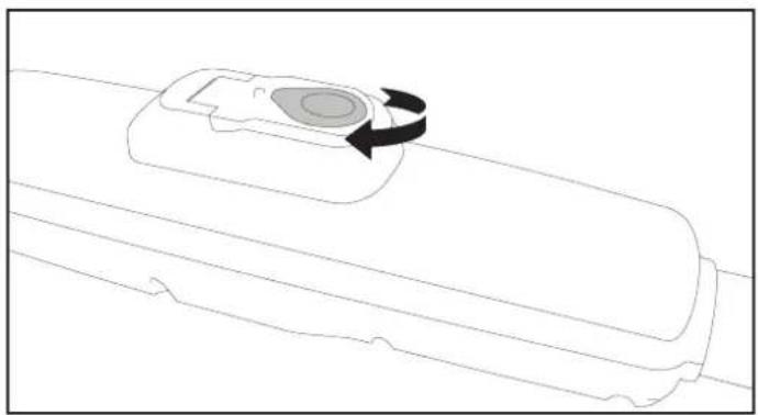
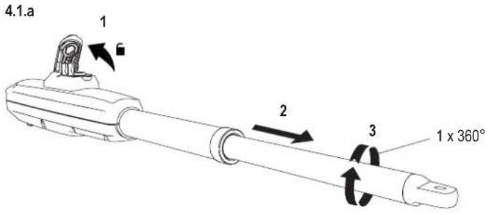
a. Pull out the tube completely and make 1 complete turn of the tube in clockwise direction see (picture 4.1.a).
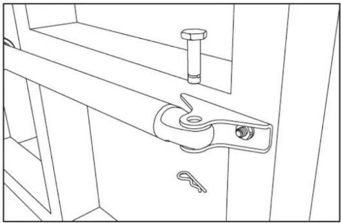
b. Connect the operator arm with the gate leaf bracket (see picture 4.1.b or 4.1.c).
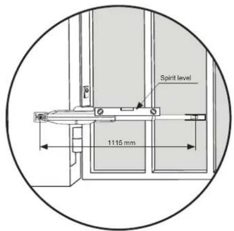
c. Preliminary fix the gate bracket on the gate leaf. Ensure that the gate touches the external hard stop. Consider the dimensions A and B from Table 1.
d. Manually open and close the gate to the required positions. Ensure the operator arm does not bind and gate is moving smoothly.
e. Make permanent connection of the gate bracket at chosen correct position.
- Repeat the procedure for the unit on the opposite side.
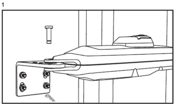
natural_image
Technical line drawing of a mechanical assembly with bolts and a bolt (no text or symbols)5. MECHANICAL INSTALLATION
4.1.a
4.1.b

natural_image
Line drawing of a mechanical latch or lever assembly with no text or symbols5.5 Hardstops Installation
5. MECHANICAL INSTALLATION
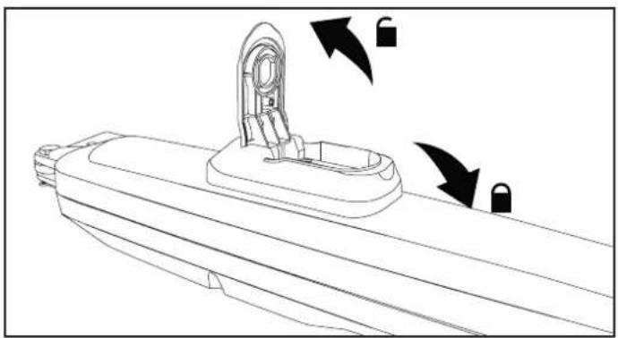
5.6 Emergency Release Mechanism
To disengage the release mechanism turn protection cap to the side, enter the key and turn it 90°. Pull the clutch up. To re-engage the release mechanism, push the clutch down and turn the key 90°.
NOTE: Same procedure applies for left and right hand units.
natural_image
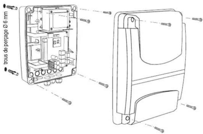
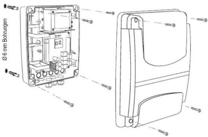
Line drawing of a mechanical component with a circular feature and rotational arrow (no text or symbols)5.7 Control Box Installation
The control box must be installed at a safe location that enables the installer to have access at all times to the logic board without the risk of the gates crushing or trapping.
It is advised that you must have full view of the gates when programming the logic board.
Install the control box in an appropriate and accessible position. The installation has to be done in accordance with local electrical regulation.
Motor 1 Connection
NOTE: The operator wired to the MOTOR 1 terminal will always open first and close last. Consider this for Basic and Advanced Settings (see Programming section).
- Feed the motor1 cable through a cable gland.
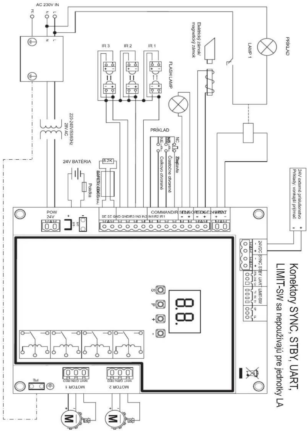
- Connect motor cables to the MOTOR 1 terminals as follows: red cable to RED terminal, green cable to GRN terminal, white cable to WHT terminal on control board.
Motor 2 Connection
NOTE: The operator wired to the MOTOR 2 terminal will always open last and close first. Consider this for Basic and Advanced Settings (see Programming section).
- Feed the motor 2 cable through a cable gland.
- Connect motor cables to the MOTOR 2 terminals as follows: red cable to RED terminal, green cable to GRN terminal, white cable to WHT terminal on control board.
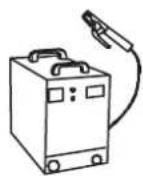
5.8 Power Wiring
Power wiring must be done by a certified electrician specialist.

natural_image
Line drawing of a mechanical component with lock indicators and directional arrows (no text or symbols)

Congratulations! Herewith the mechanical installation of your gate operator is finished. Please proceed with Programming and Basic Settings to be able to start operation.
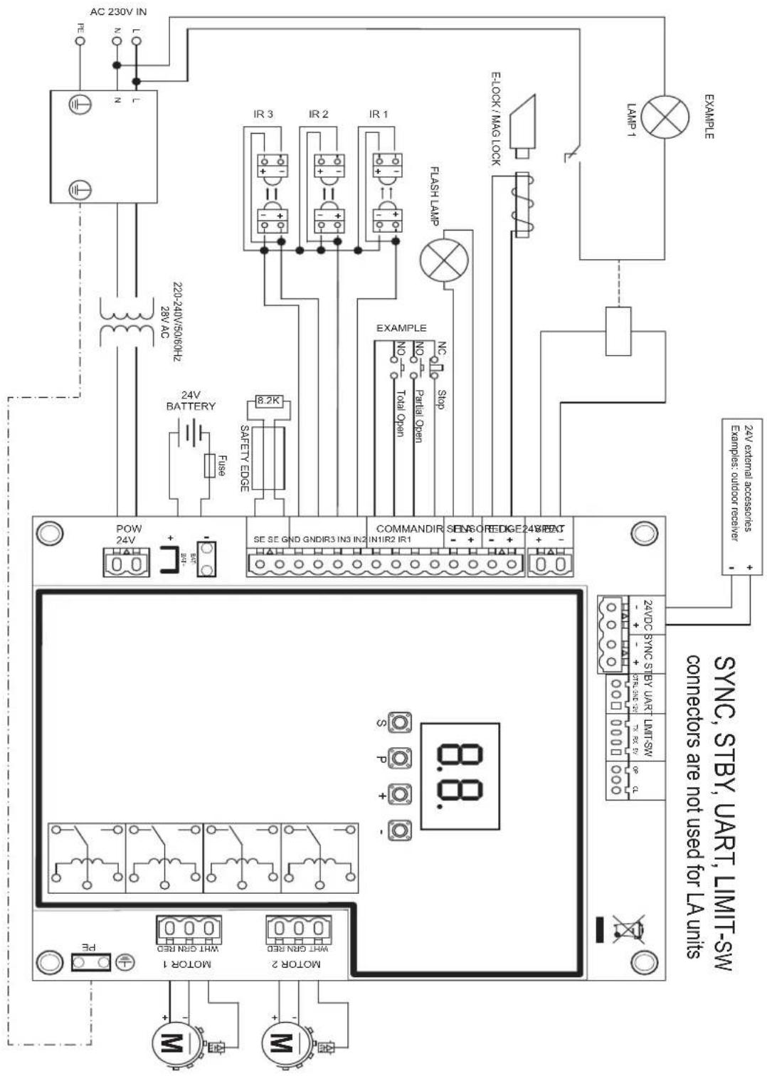
6. WIRING DIAGRAM
7. PROGRAMMING
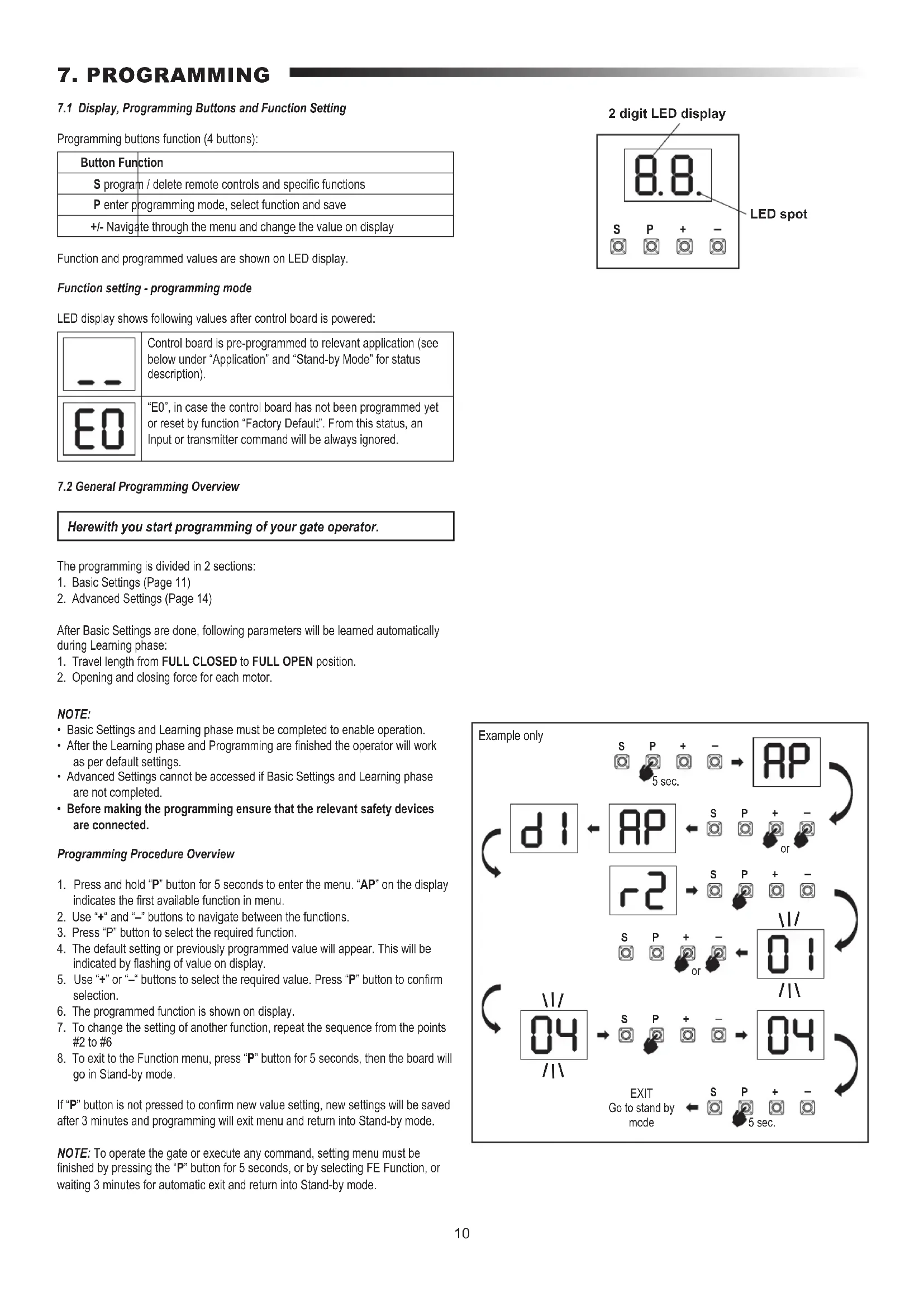
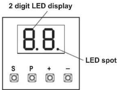
7.1 Display, Programming Buttons and Function Setting
Programming buttons function (4 buttons):
| Button Function |
| S program / delete remote controls and specific functions |
| P enter programming mode, select function and save |
| +/- Navigate through the menu and change the value on display |
Function and programmed values are shown on LED display.
Function setting - programming mode
LED display shows following values after control board is powered:
| Control board is pre-programmed to relevant application (see below under “Application” and “Stand-by Mode” for status description). | |
| “E0”, in case the control board has not been programmed yet or reset by function “Factory Default”. From this status, an Input or transmitter command will be always ignored. |
7.2 General Programming Overview
Herewith you start programming of your gate operator.
The programming is divided in 2 sections:
- Basic Settings (Page 11)
- Advanced Settings (Page 14)
After Basic Settings are done, following parameters will be learned automatically during Learning phase:
- Travel length from FULL CLOSED to FULL OPEN position.
- Opening and closing force for each motor.
NOTE:
- Basic Settings and Learning phase must be completed to enable operation.
• After the Learning phase and Programming are finished the operator will work as per default settings. - Advanced Settings cannot be accessed if Basic Settings and Learning phase are not completed.
- Before making the programming ensure that the relevant safety devices are connected.
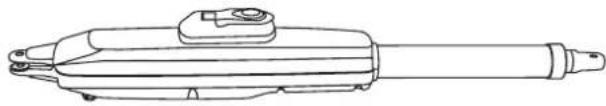
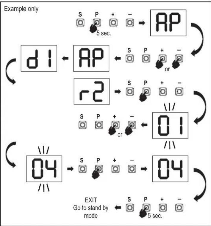
Programming Procedure Overview
- Press and hold "P" button for 5 seconds to enter the menu. "AP" on the display indicates the first available function in menu.
- Use "+" and "-" buttons to navigate between the functions.
- Press "P" button to select the required function.
- The default setting or previously programmed value will appear. This will be indicated by flashing of value on display.
- Use "+" or "-" buttons to select the required value. Press "P" button to confirm selection.
- The programmed function is shown on display.
- To change the setting of another function, repeat the sequence from the points #2 to #6
- To exit to the Function menu, press "P" button for 5 seconds, then the board will go in Stand-by mode.
If "P" button is not pressed to confirm new value setting, new settings will be saved after 3 minutes and programming will exit menu and return into Stand-by mode.
NOTE: To operate the gate or execute any command, setting menu must be finished by pressing the "P" button for 5 seconds, or by selecting FE Function, or waiting 3 minutes for automatic exit and return into Stand-by mode.
flowchart
graph TD
    A["Start"] --> B["d1"]
    B --> C["r2"]
    C --> D["04"]
    D --> E["Exit"]
    style A fill:#f9f,stroke:#333
    style B fill:#ccf,stroke:#333
    style C fill:#ccf,stroke:#333
    style D fill:#ccf,stroke:#333
    style E fill:#ccf,stroke:#333
7. PROGRAMMING
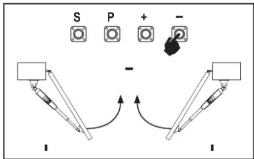
7.3 Wing Movement Direction
Before programming, move the gate manually in the middle position and re-engage release mechanism (see page 8).
Press and hold the “-” button on the control board and ensure that the motors are moving in CLOSE direction. If correct, immediately let go of the “-” button and gate stops.
If motors are moving in OPEN direction, go to the functions "d1" and "d2" and change the direction settings.
Once CLOSE direction is set correctly, leave the gate in the middle position. The operator is ready for the Learning phase.
Note: gate can be moved with „+“ and „-” buttons prior to final settings if required. Press and hold the “+” button on the control board to move the gate into OPEN position. When button is released operator stops.
Press and hold the “-” button on the control board to move the gate into CLOSE position. When button is released operator stops.
7.4 Basic Settings
Basic Settings Overview
| LED Function | ||
| Basic Settings (mandatory) | ||
 | AP Application | |
 | d1 Direction Motor 1 | |
 | d2 Direction Motor 2 | |
 | LL Limit Learning Phase | |
7.4.1 Application Settings
Application function shown on display.
This function is already pre-set at factory at value 05.


Swing gate, two motors for CHLA250 application (default)
More settings available on demand:
| 00 | No application selected |
| 04 | Swing gate, one motor for CHLA250 application |
Values 01-03 are not suitable for CHLA250 application and shall not be chosen.
7.4.2 Direction Motor 1 Settings

Direction Motor 1 function shown on display Defines movement direction of the Motor 1.
| 01 | Motor 1 is moving in closing direction |
| 02 | Motor 1 is moving in opening direction |
7.4.3 Direction Motor 2 Settings
Direction Motor 2 function shown on display. Defines movement direction of the Motor 2. Not available for "one motor" application.

| 01 | Motor 2 is moving in closing direction |
| 02 | Motor 2 is moving in opening direction |
flowchart
graph TD
    A["Component 1"] --> B["Component 2"]
    B --> C["Component 3"]
    C --> D["Component 4"]
    D --> E["Component 5"]
    E --> F["Component 6"]
    F --> G["Component 7"]
    G --> H["Component 8"]
    H --> I["Component 9"]
    I --> J["Component 10"]
    J --> K["Component 11"]
    K --> L["Component 12"]
    L --> M["Component 13"]
    M --> N["Component 14"]
    N --> O["Component 15"]
    O --> P["Component 16"]
    P --> Q["Component 17"]
    Q --> R["Component 18"]
    R --> S["Component 19"]
    S --> T["Component 20"]
    T --> U["Component 21"]
    U --> V["Component 22"]
    V --> W["Component 23"]
    W --> X["Component 24"]
    X --> Y["Component 25"]
    Y --> Z["Component 26"]
    Z --> AA["Component 27"]
    AA --> AB["Component 28"]
    AB --> AC["Component 29"]
    AC --> AD["Component 30"]
    AD --> AE["Component 31"]
    AE --> AF["Component 32"]
    AF --> AG["Component 33"]
    AG --> AH["Component 34"]
    AH --> AI["Component 35"]
    AI --> AJ["Component 36"]
    AJ --> AK["Component 37"]
    AK --> AL["Component 38"]
    AL --> AM["Component 39"]
    AM --> AN["Component 40"]
    AN --> AO["Component 41"]
    AO --> AP["Component 42"]
    AP --> AQ["Component 43"]
    AQ --> AR["Component 44"]
    AR --> AS["Component 45"]
    AS --> AT["Component 46"]
    AT --> AU["Component 47"]
    AU --> AV["Component 48"]
    AV --> AW["Component 49"]
    AW --> AX["Component 50"]
7.4.4 Limit Learning

Before starting a Learning phase ensure that:
- Other Basic Settings are completed
- Internal / external hard stops are installed (for swing gates)
- First movement will be in CLOSE direction.
Available Learning methods:
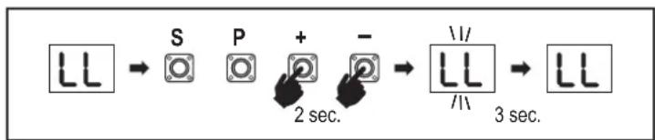
Standard Learning Mode (Automatic)
- Press and hold "+ and −" buttons for 2 seconds.
- Automatic learning process starts. LL will flash on the display during complete process.
- Wing 2 moves in CLOSE direction until the hard stop is reached, and stops.
- Wing 1 moves in CLOSE direction until the hard stop is reached, and stops for 2 seconds. Then Wing 1 starts in OPEN direction until the hard stop is reached.
- Wing 2 moves in OPEN direction until hard stop is reached, stops for 2 seconds and then moves in CLOSE direction until hard stop is reached, and stops.
- Wing 1 moves in CLOSE direction until hard stop is reached, and stops.
- Standard Learning phase is finished. LL will appear on display and board will return in stand-by mode after 3 seconds.
flowchart
graph LR
    A["LL"] --> B["S"]
    B --> C["P"]
    C --> D["+"]
    D --> E["-"]
    E --> F["LL /1"]
    F --> G["LL 3 sec."]
NOTE: In single motor application, "Wing 2" actions are not used. Following settings are done during Standard Learning Mode:
- Travel length from FULL CLOSED to FULL OPEN position.
- Opening and closing force for each motor.
- 15% of total travel in both directions is assigned for Soft Stop.
- Wing delay in opening and closing position is 2 seconds. Shall you need to change the delay please go to Advanced Settings: Delay Motor 2 (d0) and Delay Motor 1 (dC).
7. PROGRAMMING
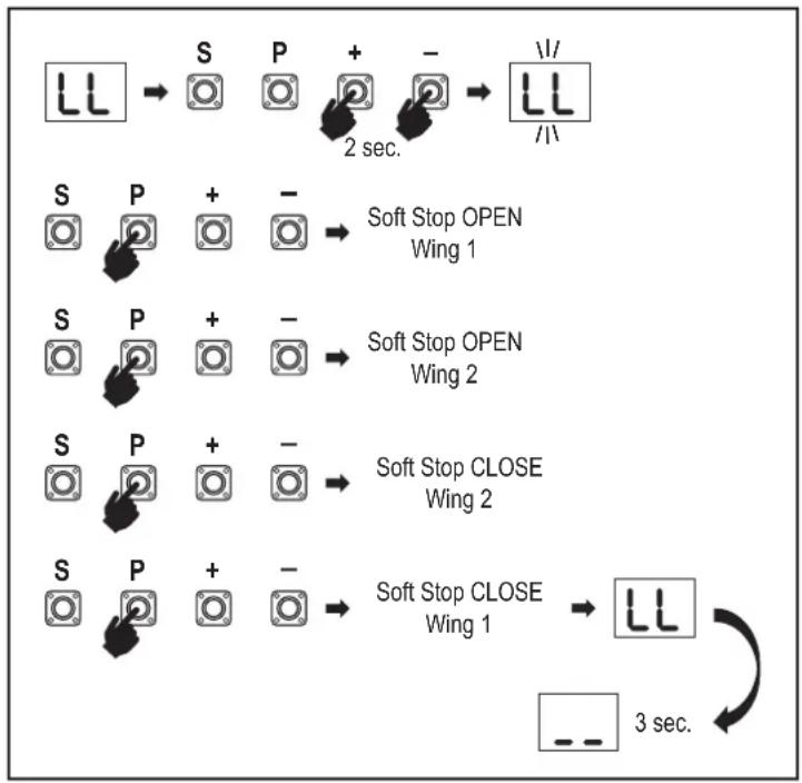
Advanced Learning Mode (manual setting of Soft Stop position)
- Press and hold "+ and −" buttons for 2 seconds.
- Automatic learning starts. LL will flash on the display during complete process.
- Wing 2 moves in CLOSE direction until hard stop is reached, and stops.
-
Wing 1 moves in CLOSE direction until hard stop is reached, and stops for 2 seconds.
-
Wing 1 starts in OPEN direction at default speed. To define start of the Soft Stop for Wing 1 in OPEN direction press "P" button at required start point. Wing 1 will continue opening until hard stop is reached, and stops.
-
Wing 2 moves in OPEN direction at default speed.
-
To define start of the Soft Stop for Wing 2 in OPEN direction press "P" button at required start point. Wing 2 will continue opening until hard stop is reached, stops for 2 seconds and then moves in CLOSE direction at default speed.
-
To define start of the Soft Stop for Wing 2 in CLOSE direction press "P" button at required start point. Wing 2 will continue closing until hard stop is reached, and stops.
-
Wing 1 moves in CLOSE direction at default speed.
-
To define start of the Soft Stop for Wing 1 in CLOSE direction press "P" button at required start point. Wing 1 will continue closing until hard stop is reached, and stops.
-
Advanced Learning phase is finished. LL will appear on display and board will return in stand-by mode after 3 seconds.
NOTE: In single motor application, "Wing 2" actions are not used.
Following settings are programmed during Advanced Learning mode:
- Travel length from FULL CLOSED to FULL OPEN position.
- Opening and closing force for each motor.
- Starting positions of the Soft Stops.
- Wing delay in opening and closing position is 2 seconds. Shall you need to change the delay please go to Advanced Settings: Delay Motor 2 (d0) and Delay Motor 1 (dC).
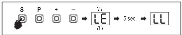
NOTE: To stop Learning phase press "S" button. The Learning process will be interrupted, "LE" will flash on LED display. After 5 seconds "LL" will appear on display indicating readiness to start Learning phase again.
If Learning process was not completed, it needs to be re-done.
ATTENTION: Learning phase must be completed to enable operation.
7.5 Stand-by Mode
After the control board is powered on and programming is finished, the LED display lights completely for 2 seconds and goes into the stand-by mode. During Stand-by mode the LED display shows current gate status.
| Two motors (default) | One motor | |
| Motor is opening, upper section of the display flashes. | ||
| Motor stops at the opening position, upper section of the display is on. | ||
| Motor is closing, lower section of the display flashes. | ||
| Motor stops at the closed position, lower section of the display is on. | ||
| Motor stops in the middle, middle of the display is on. |
flowchart
graph TD
    A["LL"] --> B["S"]
    B --> C["P"]
    C --> D["+"]
    D --> E["-"]
    E --> F["LL/II"]
    G["S"] --> H["P"]
    H --> I["+"]
    I --> J["-"]
    J --> K["Soft Stop OPEN Wing 1"]
    L["S"] --> M["P"]
    M --> N["+"]
    N --> O["-"]
    O --> P["Soft Stop OPEN Wing 2"]
    Q["S"] --> R["P"]
    R --> S["+"]
    S --> T["-"]
    T --> U["Soft Stop CLOSE Wing 2"]
    V["S"] --> W["P"]
    W --> X["+"]
    X --> Y["-"]
    Y --> Z["Soft Stop CLOSE Wing 1"]
    AA["LL"] --> AB["3 sec."]
    AC["--"] --> AD["3 sec."]
Herewith the Basic Settings are completed. You can leave Programming and operate your gate or proceed with Advanced Settings.
7. PROGRAMMING
7.6 Programming and Erasing of Remote Controls, Radio Accessories and myQ Devices
Program remote control devices (transmitters and wireless wall controls): NOTE: the remote controls delivered with the operator are already factory pre-learned to the operator (top button near the LED) and do not require extra programming.
- Press and release "S" button. An LED spot turns ON in the display. The operator will stay in Radio programming mode for 3 minutes. Any radio accessory device can be learned within first 30 seconds. During the remaining 2.5 minutes only myQ devices can be learned.
- Chose the required button on your transmitter and hold it until the dot in the display turns off.
To program a new remote control repeat the sequence.
To program a wireless keypad, please follow the respective manual of the accessory.
Programming Transmitter in Partial opening
Press and hold "S" and "+" buttons at the same time, until the LED spot starts flashing. Press and hold the desired free button on transmitter to program the Partial Opening Mode.
The LED spot turns off when the programming is finished. If there is a light connected to SPEC contact it will flash once.
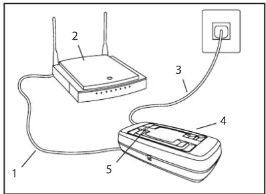
Program myQ gateway (830REV-01):
1. Connect
Connect ethernet cable (1) provided with gateway to router (2). Use the plug valid for your country (not all models). Connect power (3) to the internet gateway (4). When the internet gateway connects to the internet, the green light (5) will stop blinking and will light solid. A connected set of IRs is mandatory for myQ operation.
2. Create an account
Download the free myQ App from App Store or Google Play Store and create an account. If you already have an account, use your username and password.
3. Register the internet gateway
Enter the Serial Number located on the bottom of the internet gateway when prompted.
4. Add myQ devices
To add your gate operator to the registered gateway follow the instructions on the app. When adding a new myQ capable gate operator press and release "S" button on operator control board. An LED spot turns ON in the control board display.
Note: After you add a device, the blue light on the internet gateway will appear and stay on. Press "S" button on the operator control board to exit the radio programming mode.
5. Test
After having installed and registered correctly you may now test the following features: open or close the gate, request status GATE OPEN or GATE CLOSED.
For more functions see www.chamberlain.eu
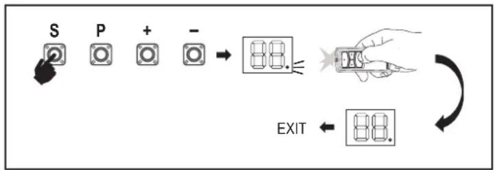
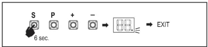
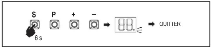
Erase radio control devices (transmitters, wireless wall controls, wireless keypads):
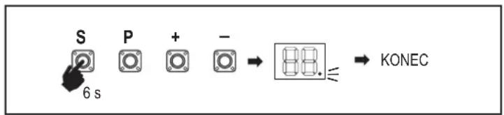
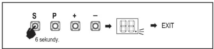
Press and hold "S" button for > 6 seconds. All radio control devices (transmitters, wall controls, keypads) are erased. The LED spot in the display turns OFF. Note: It is not possible to erase radio control devices individually.
Erase myQ devices:
- Erase remote control devices first as indicated above.
- Within next 6 seconds press and hold "S" button. An LED spot turns ON in the display.
- Press and hold "S" button for > 6 seconds. All myQ devices are erased. The LED spot in the display turns OFF.
NOTE: It is not possible to erase myQ devices individually. It is not possible to erase myQ devices only.
flowchart
graph LR
    S["State S"] --> P["State P"]
    P --> +[+]
    + --> -["-"]
    - --> 88["88"]
    88 -->|OK| H["Hand Icon"]
    88 -->|Exit| Exit["Exit"]
flowchart
graph LR
    A["S"] --> B["P"]
    B --> C["+"]
    C --> D["-"]
    D --> E["88."]
    E --> F["EXIT"]
    G["6 sec."] --> A
7. PROGRAMMING
7.7 Advanced Settings
Herewith you start with Advanced Settings.
7.7.1 Overview Advanced Settings
| LED Function | |||
| tr | tr Transmitter | ||
| r1 | r1 IR1 | photocell | |
| r2 | r2 IR2 | photocell | |
| r3 | r3 IR3 | photocell | |
| i1 | i1 Input 1 command | ||
| i2 | i2 Input 2 command | ||
| i3 | i3 Input 3 command | ||
| Pd | Pd Partial Opening Motor 1 only | ||
| d0 | d0 Delay Motor 2 in OPEN | ||
| dC | dC Delay Motor 1 in CLOSE | ||
| tC | tC Timer To Close (TTC) | ||
| rt | rt Reversal time after impact | ||
| EL | EL E-lock | ||
| rb | rb Relief Motor 1 for E-lock | ||
| LED Function | |||
| FL | FL Flashing Light | ||
| PF | PF Pre-Flashing | ||
| SP | SP Special contact | ||
| St | St START Speed in OPEN and CLOSE | ||
| Cn | Cn Maintenance counter | ||
| Fd | Fd Factory default | ||
| FE | FE Finish and Exit | ||
7.7.2 Transmitter Settings
Transmitter function defines how Transmitter commands are working.
Note: Under settings "01", "02" and "03", TTC timer will be overridden by a transmitter command and will CLOSE the gate.
Under setting "04", active TTC timer countdown will be re-set to start again by Transmitter command.
| 01 | Residential Mode: Open – Close – Open |
| 02 | Standard Mode: Open – Stop – Close – Stop – Open (Default) |
| 03 | Automatic with Stop Mode: Open – Stop – Close – Open |
| 04 | Car Park Mode: Open, to complete Open position. Additional command during the opening will be ignored |
7.7.3 Infrared Photocells Settings
IR functions define functioning mode of Infrared Photocells (IR). IRs will be auto-learned when installed. Each of the 3 IR sets can be programmed individually.


NOTE: Depending on the chosen settings the Partial Opening inputs or Remote Controls commands will not be executed in both OPEN or CLOSE direction if the IR beam is obstructed.
If IRs are removed, the control board power must be turned OFF/ON for two times to unlearn.
For check and maintenance of the photocells see the manual of the photocells.
| 01 | IR active on CLOSE movement. If IR beam is obstructed, gate reverses in complete OPEN position (Default). |
| 02 | IR active on OPEN movement. If IR beam is obstructed gate stops. When obstruction disappears the gate continues to OPEN. |
| 03 | IR is active on OPEN and CLOSE movement. If IR beam is obstructed on CLOSE movement, gate stops and after the obstruction disappears gate reverses in complete OPEN position. If IR beam is obstructed on OPEN movement, gate stops. When obstruction disappears the gate continues to OPEN. |
| 04 | IR active on CLOSE movement. If IR beam is obstructed, gate reverses in complete OPEN position. The activated TTC function will be overridden 2 seconds after the beam obstruction is eliminated and will start CLOSE movement not waiting till the end of TTC time end. |
7.7.4 Input Settings

Inputs function defines the way Input commands from external accessories are executed. Each of the 3 Inputs can be programmed individually.
NOTE: Under settings "01", "02" and "03", TTC timer will be overridden by an Input command and will CLOSE the gate. Under setting "06", active TTC timer count-down will be re-set to start again by an Input command
7. PROGRAMMING
| 01 | Open – Close – Open |
| 02 | Open – Stop – Close – Stop – Open (Default) |
| 03 | Open – Stop – Close – Open |
| 04 | Partial opening Motor 1 only |
| 05 | STOP (NC contact) |
| 06 | Open, to complete OPEN position. Additional Open command during the opening will be ignored |
| 07 | Close, to complete CLOSE position. Additional Close command during the closing will be ignored |
| 08 | Open – Stop – Open - Stop |
| 09 | Close – Stop – Close - Stop |
| 10 | Open, hold to run |
| 11 | Close, hold to run |
7.7.5 Partial Opening Motor 1

Partial opening Motor 1 only gives you the ability to open active leaf to a pre-set value only.
NOTE: Pd command will work starting from Close limit position and during closing movement. If a Pd command is executed from a complete OPEN position, the gate will close.
An Open or transmitter command will always override the Pd command.
| 01 | 50% opening travel |
| 02 | 75% opening travel (default) |
| 03 | 100% opening travel |
- Press and hold "S" and "+" buttons on the control board at the same time, until the LED spot starts flashing.
- Press and hold the desired free button on transmitter to program the Partial Opening Mode.
- The LED spot turns off when the programming is finished. If there is a light connected to SPEC contact it will flash once.
7.7.6 Delay Motor 2 in Open Direction

Delay Motor 2 in OPEN direction function defines time delay for Motor 2 in OPEN direction. Not available for single motor application.
Not executed during reversal or after IR beam interruption in both directions.
| 00 | no delay (both wings start opening at the same time) |
| 01 | 1 second |
| 02 | 2 seconds (Default) |
| 03 | 3 seconds |
| 04 | 4 seconds |
7.7.7 Delay Motor 1 in Close Direction

Delay Motor 1 in CLOSE direction function defines time delay for Motor 1 in CLOSE direction. Not available for the single motor application. Not executed during reversal or after IR beam interruption in both directions.
| 00 | no delay (both wings start in the same time) |
| 01 | 1 second |
| 02 | 2 seconds (Default) |
| ... ... seconds | |
| 20 | 20 seconds |
7.7.8 Timer To Close

Timer to close (TTC) function enables automatic closing of the gate from a complete OPEN position after a pre-set period of time. Minimum one pair of Chamberlain Infrared Photocells (IR) has to be installed to monitor closing movement to enable TTC operation. TTC will not work if IR are protecting opening movement only. TTC will also work with activated partial opening. If TTC function is active, timer is counting down, and the IR beams are interrupted, the TTC timer shall re-start.
| 00 | TTC not active (Default) | 05 | 1 minute |
| 01 | 10 seconds | 06 | 1.5 minutes |
| 02 | 20 seconds | 07 | 2 minutes |
| 03 | 30 seconds | 08 | 3 minutes |
| 04 | 45 seconds | 09 | 5 minutes |
7.7.9 Reversal Time after Impact

Reversal time after impact function defines reversal behavior after obstacle obstruction during closing or opening movement. This reversal behavior is valid both for motor force detection and safety edge application.
| 01 | 2 seconds reversal and Stop |
| 02 | Reversal back up to the end limit position (Default) |
| 03 | During Closing movement, upon impact gate reverses up to Open position. During Opening movement, upon impact gate reverses for 2 seconds and stops |
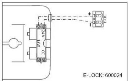
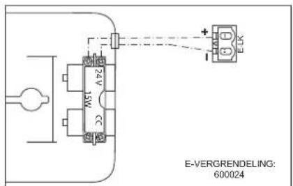
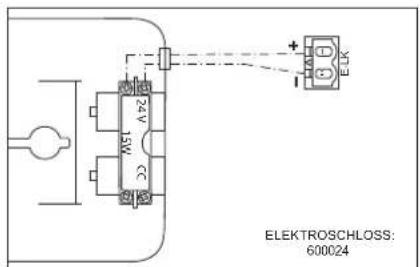
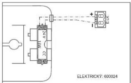
7.7.10 E-Lock / Mag-Lock Settings

E-Lock function defines e-lock/mag-lock behavior. 24VDC – 500mA e-lock or mag-lock can be connected.
| 00 | e-lock/mag-lock not installed (Default) |
| 01 | e-lock active for 1 second prior to Motor 1 start in Open direction |
| 02 | e-lock active for 2 seconds prior to Motor 1 start in Open direction |
| 03 | Magnetic lock, constantly active at gate CLOSED, constantly inactive during OPEN and CLOSE movement, gate OPEN or STOP position. Magnetic lock will be deactivated in Battery Back-up mode. |
7. PROGRAMMING
7.7.10a Relief Motor 1 for E-Lock

Relief Motor 1 for E-Lock function enables to briefly push Motor 1 in CLOSE direction before engaging e-lock to relieve excess pressure on e-lock. Not available if EL Function is set to "00" or "03" (e-lock not connected / mag-lock connected).
| 00 | deactivated (Default) |
| 01 | 1 second activated |
| 02 | 2 seconds activated |
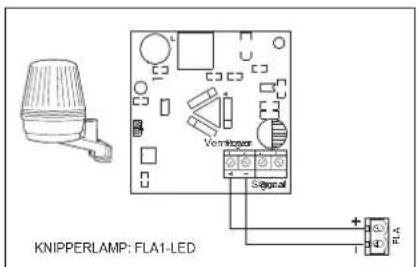
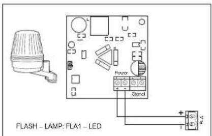
7.7.11 Flashing Light Settings

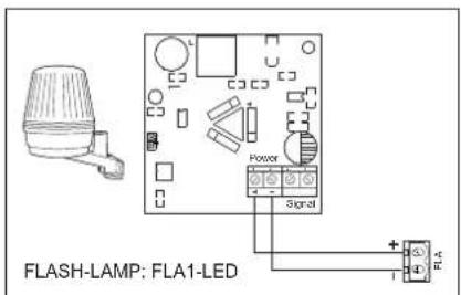
Flashing Light function allows to select which type of Flashing Lamp is connected. 24VDC- max 500 mA Flashing lamp (FLA1-LED) can be connected.
| 00 | no flashing lamp installed (Default) |
| 01 | continuous 24V supply - for flashing lamp with own control board (FLA1-LED) |
| 02 | interrupted 24V supply - for flashing lamp without own control board |
7.7.11a Pre-Flashing

Pre-Flashing function defines time interval of pre-flashing of the flashing lamp prior to gate movement. Function not active if Flashing Lamp (FL) Function is set to "00".
| 00 | no pre-flashing (Default) | 03 | 3 seconds |
| 01 | 1 second | 04 | 4 seconds |
| 02 | 2 seconds | 05 | 5 seconds |
7.7.12 Special Contact Settings

Special Contact function defines relay activation time.
A 24V max 500mA relay can be connected to manage other devices, e.g. courtesy light. The time set here will also control countdown for myQ remote light.
| 00 | no activation (Default) | 05 | 1.5 minutes |
| 01 | 15 seconds | 06 | 2 minutes |
| 02 | 30 seconds | 07 | 3 minutes |
| 03 | 45 seconds | 08 | 4 minutes |
| 04 | 1 minute | 09 | 5 minutes |
7.7.13 Start Speed in Open and Close Directions

Start Speed function allows switching the Soft-Start in OPEN and CLOSE directions ON and OFF.
| 00 | deactivated (Default) |
| 01 | Soft Start active: motors will accelerate gradually until they reach standard speed. |
7.7.14 Maintenance Counter

Maintenance Counter function allows to set maintenance interval in cycles. 4 seconds pre-flashing of the Flashing Lamp will be a signal the interval is reached. If PF Function (Pre-Flashing) is active then 4 second pre-flashing will be added to the set time. To reset counter after maintenance is done, it will be enough to program the cycles one more time.
| 00 | no counter (Default) | ... ... cycles | |
| 20 | 20000 cycles | ||
| 01 | 1000 cycles | ||
| 02 | 2000 cycles | ||
7.8 Factory Default

Factory default function resets control board to the original factory set-ups. All settings, including limit settings, will be erased. LED display will show "E0". Programmed remote controls will remain learned. If Remote control accessories need to be erased refer to the respective Radio Controls Programming section of this manual.
| 00 | no reset (Default) |
| 01 | reset to the factory default settings |
7.9 Finish and Exit

To exit the programming phase and save all changes,
move to FE function and press "P" button. The control board will go into Stand-by mode and is ready to work.
There are also other ways to exit the programming and save settings:
- Press and hold "P" button for 5 seconds
- Wait 3 minutes after the last changes in the programming for automatic exit
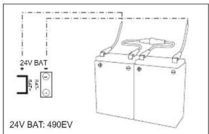
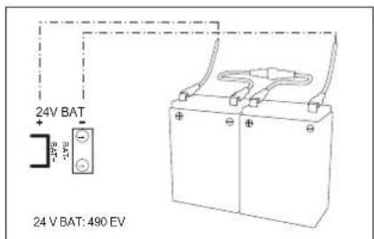
8. BATTERY BACKUP
Battery Back-Up Mode

2 Optional 12V, 2.2Ah lead batteries SKU 490EV (optional, not included) can be mounted inside the E-Box. Follow the manual of SKU 490EV for exact installation procedure. A Flashing lamp (if mounted) will flash 2 seconds every 10 minutes indicating BBU mode and power loss. Control board will switch into stand-by mode with active radio receiver accepting radio control device commands only. All other accessories and peripheral devices will not be functioning.
When in Battery Back-up mode, myQ Smartphone Control and wireless myQ devices will be disabled. Full charged battery capacity shall support up to \~20 cycles at a rate of 2 per hour. After 24 hours of BBU mode the battery shall provide power for 1 complete opening and closing cycle. Please note that only the specified battery can be use. Use of any other battery leads to loss of warranty and loss of liability of Chamberlain for any related damages resulting from use of unspecified batteries.
- ERROR CODES
| LED | Error code | Issue Possible | reason Solution | |
| E0 | E0 | Press transmitter, but no gate movement | AP is set to 00 Check if AP is set to 00. If yes, change to correct application setting. | |
| E1 | E1 | Gate do not close, but can open. | 1) IR1 is not connected, or wire is cut. 1) Check if IR1 is not connected, or wire is cut. | |
| 2) IR1 wire is shorted out or reverse connected. 2) Check IR1 connection, change wires if needed. | ||||
| 3) IR1 is not aligned or blocked for a moment. | 3) Align IR transmitter and receiver to make sure both LED is on, instead of blinking. Make sure there is nothing hanging on gate that may cause IR blocking. | |||
| E2 | E2 | Gate can close when it is at open limit, but cannot open when it's at close limit. | 1) IR2 is not connected, or wire is cut. 1) Check if IR2 is not connected, or wire is cut. | |
| 2) IR2 wire is shorted out or reverse connected. 2) Check IR2 connection, change wires if needed. | ||||
| 3) IR2 is not aligned or blocked for a moment. | 3) Align IR transmitter and receiver to make sure both LED is on, instead of blinking. Make sure there is nothing blocking the IR. | |||
| E3 | E3 | Press transmitter, but no gate movement. | 1) IR3 is not connected, or wire is cut. 1) Check if IR3 is not connected, or wire is cut. | |
| 2) IR3 wire is shorted out or reverse connected. 2) Check IR3 connection, change wires if needed. | ||||
| 3) IR3 is not aligned or blocked for a moment. | 3) Align IR transmitter and receiver to make sure both LED is on, instead of blinking. Make sure there is nothing hanging on gate that may cause IR blocking in short time. | |||
| E4 | E4 | Press transmitter, but no gate movement. | 1) Safety edge is not connected with 8.2kohm resistor. | 1) Check if the 8.2 kOhm safety edge is properly connected or if the 8.2 kOhm resistor is installed. |
| 2) Safety edge wire is shorted out. 2) Check safety edge wires and replace wire if needed. | ||||
| 3) Safety edge is pressed. 3) Check if safety edge is pressed. | ||||
| E5 | E5 | Press transmitter, but no gate movement. | 1) STOP switch is open. 1) Check if STOP switch is open or damaged. | |
| 2) STOP switch is not connected. | 2) Check if STOP switch is disconnected. If yes, then reconnect STOP switch or change the respective Input setting to other value. | |||
| E7 | E7 | Press transmitter, but no gate movement. | Control board amplifier for Motor 1 fail. | Switch off power for 20 seconds and reset to check if control board recovers. If not, change control board. |
| E8 | E8 | Press transmitter, but no gate movement. | Control board amplifier for Motor 2 fail. | Switch off power for 20 seconds and reset to check if control board recovers. If not, change Control board. |
| E9 | E9 | Press transmitter, but no gate movement. | Control board memory mistake. | Switch off power for 20 seconds and reset to check if control board recovers. If not, change control board. |
| F1 | F1 | Motor 1 stop and reverse during open or close. | Motor 1 is blocked. Check and remove obstruction. | Clean gate. |
| F2 | F2 | Motor 2 stop and reverse during open or close. | Motor 2 is blocked. Check and remove obstruction. | Clean gate. |
| F3 | F3 | Motor 1 stop and reverse during open or close. | Motor 1 stall or speed sensor is damaged. Check if motor 1 stalled or speed sensor is damaged. | |
| F4 | F4 | Motor 2 stop and reverse during open or close. | Motor 2 stall or speed sensor is damaged. Check if motor 2 stalled or speed sensor is damaged. | |
| F5 | F5 | Press transmitter, but motor has no action. | Radio module fail. | Switch off power for 20 seconds and reset to check if control board recovers. If not, change control board. |
| F6 | F6 | Gate reverse during closing. Low battery power. Charge battery. | ||
| F7 | F7 | Press transmitter, but no gate movement. | Control board damaged. | Switch off power for 20 seconds and reset to check if control board recovers. If not, change control board. |
| F9 | F9 | Press transmitter or push button, but motor has no action. | AP menu is reset to factory default. Relearn limits. | |
| LE | LE | Motor stops suddenly. Press C button during limit learning. Relearn limits. | ||
- TECHNICAL DATA
| CHLA250EVC | ||
| Input Voltage VAC 220-240 | ||
| Input frequency Hz 50/60 | ||
| Motor Voltage VDC 24V | ||
| Standby consumption (without accessories) | W 3.7 | |
| Motor Rated Power (CHLA250EVC = 2 x CHLA250-24) | W 100 | |
| Rated Force N 800 | ||
| Maximum Motor Pushing/Pulling Force N | 1250 | |
| Cycles per hour 5 | ||
| Max. cyles per day 20 | ||
| Max. wing weight m / kg | 1.5m / 200kg2m / 150kg2.5m / 100Kg | |
| Max. opening angle | 110° | |
| Time to open to 90° | s | 15-18 |
| Piston /Screw travel length | mm | 300 |
| Cable length | m | 1.5 |
| End Limit System | Encoder with hard stops | |
| Operating Radio Frequency | MHz | RX 433MHz (433.30MHz, 433.92MHz, 434.54MHz)RX 868MHz (868.30MHz, 868.95MHz, 869.85MHz)TX 865.125MHz, 865.829MHz, 866.587MHz<10mW |
| Sending power | ||
| Code | Security+ 2.0 | |
| Max. nr of remotes | 180 | |
| Max. nr. of keypads | 4 | |
| Max. nr. of myQ devices | 16 | |
| External accessory power | 24VDC - max. 500mA | |
| Flahing lamp connector | 24VDC - max. 500mA | |
| E-Lock /Magnetic lock conenctor | 24VDC - max. 500mA | |
| External relay | 24VDC - max. 500mA | |
| Safety edge | 8,2 kOhm | |
| Max. nr. of IRs | 3 | |
| Max. nr. of external inputs | 3 | |
| Battery back-up unit | 2 x 12V, 2.2Ah SKU 490EV | |
| Ingress protection Motor | IP | 44 |
| Ingress protection control board | IP | 65 |
| Noise Level dB | < 70 db(A) | |
| Working temperature | °C | -20°C to +55°C |
| Weight (kit) | Kg | 19,6 |
| Transmitter Frequency | TX4REV-F | 868MHz (868.30MHz, 868.95MHz, 869.85MHz) |
| Sending power | <10mW | |
| Battery | CR2032 3V |
11. MAINTENANCE
Replace Batteries in The Remote Control
Battery of the remote control:
The batteries in the remote have an extremely long life. If the transmission range decreases, the batteries must be replaced. Batteries are not covered by the guarantee.
Please observe the following instructions for battery:
Batteries should not be treated as household waste. All consumers are required by law to dispose of batteries properly at the designated collection points. Never recharge batteries that are not meant to be recharged.
Danger of explosion!
Keep batteries away from children, do not short-circuit them or take them apart. See a doctor immediately, if a battery is swallowed. If necessary, clean contacts on battery and devices before loading. Remove flat batteries from the device immediately!
Increased risk of leakage!
Never expose batteries to excessive heat such as sunshine, fire or similar!
There is increased risk of leakage!
Avoid contact with skin, eyes and mouth. Rinse the parts affected by battery acid with plenty of cold water and consult a doctor immediately. Use only batteries of the same type. Remove the batteries if the device is not being used for a long time.
Replacing battery:
To replace battery, turn remote control around and open the case with a screwdriver. Lift cover and lift control board below. Slide battery to one side and remove. Watch polarity of battery! Assemble again from in reverse direction.
ATTENTION!
Danger of explosion if battery is replaced improperly. Replacement only by identical or equivalent type (CR2032) 3V.
CAUTION
Risk of explosion if the battery is replaced by an incorrect type.
Do not ingest battery, Chemical Burn Hazard.
This product contains a coin battery. If swallowed, button batteries can cause injuries, or death.
WARNING
- Keep batteries out of sight and out of the reach of children, button/coin batteries can be dangerous for children.
- Dispose of used button batteries immediately. Do not use defect/swallowed batteries.
- Check periodically if the battery compartments is secure, stop using if defect.
- If batteries might have been swallowed or placed inside any part of the body, seek immediate medical attention.


The drive mechanism
The drive mechanism is maintenance free. Check the gate fittings and the drive mechanism at regular intervals (monthly) are securely fixed. Release the drive and check that the gate functions properly. Unless the gate runs smoothly it will not operate correctly with the drive mechanism. The drive cannot eliminate the problems caused by a gate that does not work correctly.
Limit switch adjustment and force regulation
These settings must be checked and undertaken properly during the installation of the opener! Due to weathering, minor changes can occur during operation of the opener that need to be addressed by a new setting. This can particularly happen in the first year of operation. Follow the instructions for setting travel limits and force (refer to section Limit Learning Phase, pages 11 and 12) carefully and re-check the automatic safety reverse after each resetting!
Disassembly
IMPORTANT Notice! Follow the safety notices. See "Safety instructions" (pages 2 and 3). The sequence described in the "installation" section, but in opposite order. Ignore the setup instructions.
12. DISPOSAL

Our electrical and electronic equipment may not be disposed of with household waste and must be disposed of after use properly in accordance with WEEE Directive EU: 2012/19/EU; GB UK(NI): SI 2012 nr. 19 on waste electrical and electronic equipment in order to ensure that materials are recycled. Collecting waste electrical equipment separately means environmentally-friendly disposal and is completely free of charge for the consumer. WEEE reg. no. in Germany: DE66256568.
Any waste packaging left over with the end consumer must be collected separately from mixed waste, in accordance with the Directive. Packaging may not be disposed of with household waste, organic waste or in nature. Packaging material must be separated according to its material and disposed of in the recycling containers provided and in certain council recycling bins.

Our batteries are marketed in compliance with the law. The 'crossed-out waste bin' indicates that batteries may not be disposed of with household waste. Batteries included in the product (technical data). In order to avoid causing harm to the environment or people's health, used batteries must be returned for regulated dis-
posal at council recycling centres or via retail outlets, as is prescribed by law. Batteries may only be brought for disposal once fully discharged and, in the case of lithium batteries, with their terminals taped over. The batteries can be easily removed from our equipment for disposal. Registration number in Germany: 21002670.
13. WARRANTY
Your statutory rights are not affected by this manufacturer's warranty. Please see www.chamberlain.eu for terms of warranty.
14. DECLARATION OF CONFORMITY
The manual consists of these operating instructions and the declaration of conformity.
The radio equipment type (TX4REV-F) is in compliance with Directive 2014/53/EU and for UK with Radio Equipment Regulation SI 2017 No. 1209.
The full text of the EU declaration of conformity is available at the following internet address: https://doc.chamberlain.de
TABLE DES MATIÈRES
natural_image
Line drawing of a welding torch (no text or symbols)natural_image
Line drawing of a drill bit with three labeled buttons (H, =, H) below it, no text or symbols present.


4. VUE D'ENSEMBLE DE L'AUTOMATISME DE PORTAIL
natural_image
Technical line drawing of a mechanical assembly with bolts and a bolt (no text or symbols)5. INSTALLATION MÉCANIQUE
4.1.a
4.1.b
natural_image
Line drawing of a mechanical latch or lever assembly with no text or symbolsnatural_image
Line drawing of a mechanical component with a circular feature and rotational arrow (no text or symbols)natural_image
Technical line drawing of a mechanical component with lock indicators and directional arrows (no text or symbols)
flowchart
graph TD
    A["Component S"] --> B["Arrow to Right"]
    C["Component P"] --> D["Arrow to Left"]
    E["Component +"] --> F["Arrow to Right"]
    G["Component -"] --> H["Arrow to Left"]
    I["Component I"] --> J["Arrow to Right"]
    K["Arrow to Left"] --> L["Arrow to Right"]
flowchart
graph LR
    A["S"] --> B["6s"]
    C["P"] --> D["+"]
    E["+"] --> F["-"]
    G["□"] --> H["88."]
    I["≤"] --> J["QUITTER"]
7.7 Réglages avancés
natural_image
Line drawing of a handheld electric shaver tool (no text or symbols)natural_image
Technical line drawing of a mechanical assembly with bolts and a bracket (no text or symbols)5. MECHANISCHE INSTALLATIE
CHLA250EVC

4.1.b

natural_image
Line drawing of a mechanical bracket with a handle and mounting hole (no text or symbols)natural_image
Line drawing of a mechanical component with a circular feature and rotational arrow (no text or symbols)natural_image
Line drawing of a mechanical component with lock indicators and directional arrows (no text or symbols)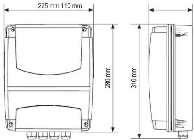


7. PROGRAMMERING
7. PROGRAMMERING
7.6 Programmeren en wissen van afstandsbedieningen, radioaccessoires en myQ-apparaten
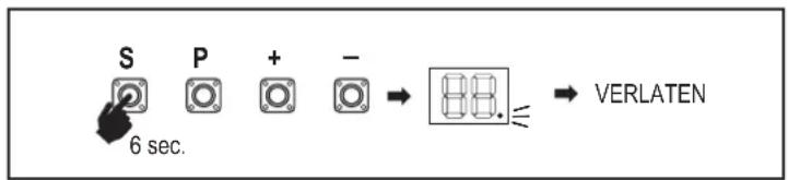
flowchart
graph LR
    A["S"] --> B["P"]
    B --> C["+"]
    C --> D["-"]
    D --> E["88."]
    E --> F["VERLATEN"]
    style A fill:#fff,stroke:#000
    style B fill:#fff,stroke:#000
    style C fill:#fff,stroke:#000
    style D fill:#fff,stroke:#000
    style E fill:#fff,stroke:#000
    style F fill:#fff,stroke:#000
7. PROGRAMMERING
natural_image
Line drawing of a handheld electric shaver tool (no text or symbols)natural_image
Technical line drawing of a mechanical assembly with bolts and a bracket (no text or symbols)5. MECHANISCHE MONTAGE
CHLA250EVC

4.1.b

natural_image
Line drawing of a mechanical bracket with a handle and mounting bracket (no text or symbols)natural_image
Line drawing of a mechanical component with a circular feature and rotational arrow (no text or symbols)natural_image
Technical line drawing of a mechanical component with lock indicators (no text or symbols)
7. PROGRAMMIERUNG

flowchart
graph LR
    A["S"] --> B["P"]
    B --> C["+"]
    C --> D["-"]
    D --> E["88."]
    E --> F["EXIT"]
7. PROGRAMMIERUNG
-
SCHÉMA ZAPOJEN....9
-
PROGRAMMING....10
natural_image
Line drawing of a welding torch (no text or symbols)5. MECHANICKÁ MONTÁŽ
5. MECHANICKÁ MONTÁŽ
natural_image
Technical line drawing of a mechanical assembly with bolts and a bolt (no text or symbols)5. MECHANICKÁ MONTÁŽ
CHLA250EVC

natural_image
Line drawing of a mechanical bracket with a handle and mounting bracket (no text or symbols)5. MECHANICKÁ MONTÁŽ
natural_image
Line drawing of a mechanical component with a circular feature and rotational arrow (no text or symbols)natural_image
Technical line drawing of a mechanical component with lock indicators (no text or symbols)

7. PROGRAMOVÁNÍ
natural_image
Line drawing of a handheld electric shaver tool (no text or symbols)natural_image
Technical line drawing of a mechanical assembly with bolts and a bolt (no text or symbols)5. MECHANICKÁ INŠTALÁCIA
CHLA250EVC
4.1.b
natural_image
Line drawing of a mechanical bracket with a handle and mounting feet (no text or symbols)natural_image
Line drawing of a mechanical component with a circular feature and rotational arrow (no text or symbols)natural_image
Technical line drawing of a mechanical component with lock indicators (no text or symbols)

6. SCHÉMA ZAPOJENIA

7. PROGRAMOVANIE
7.PROGRAMOVANIE
Chamberlain GmbH
info@chamberlain.com